Page 4 of 216
These are some of the symbols you may see on your vehicle.
Vehicle Symbol Glossary
Safety Alert
See Owner's Guide
Fasten Safety BeltAir Bag-Front
Air Bag-SideChild Seat
Child Seat Installation
WarningChild Seat Tether
Anchorage
Brake SystemAnti-Lock Brake System
Brake Fluid -
Non-Petroleum BasedTraction Control
Master Lighting SwitchHazard Warning Flasher
Fog Lamps-FrontFuse Compartment
Fuel Pump ResetWindshield Wash/Wipe
Windshield
Defrost/DemistRear Window
Defrost/Demist
Power Windows
Front/RearPower Window Lockout
Introduction
4
Page 100 of 216

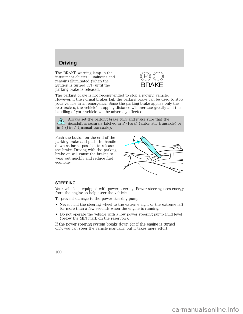
The BRAKE warning lamp in the
instrument cluster illuminates and
remains illuminated (when the
ignition is turned ON) until the
parking brake is released.
The parking brake is not recommended to stop a moving vehicle.
However, if the normal brakes fail, the parking brake can be used to stop
your vehicle in an emergency. Since the parking brake applies only the
rear brakes, the vehicle's stopping distance will increase greatly and the
handling of your vehicle will be adversely affected.
Always set the parking brake fully and make sure that the
gearshift is securely latched in P (Park) (automatic transaxle) or
in 1 (First) (manual transaxle).
Push the button on the end of the
parking brake and push the handle
down as far as possible to release
the brake. Driving with the parking
brake on will cause the brakes to
wear out quickly and reduce fuel
economy.
STEERING
Your vehicle is equipped with power steering. Power steering uses energy
from the engine to help steer the vehicle.
To prevent damage to the power steering pump:
²Never hold the steering wheel to the extreme right or the extreme left
for more than a few seconds when the engine is running.
²Do not operate the vehicle with a low power steering pump fluid level
(below the MIN mark on the reservoir).
If the power steering system breaks down (or if the engine is turned
off), you can steer the vehicle manually, but it takes more effort.
P!
BRAKE
Driving
100
Page 115 of 216

Roadside coverage beyond basic warranty
In the United States, you may purchase additional roadside assistance
coverage beyond this period through the Ford Auto Club by contacting
your Ford or Lincoln Mercury dealer.
Similarly in Canada, for uninterrupted Roadside Assistance coverage, you
may purchase extended coverage prior to your Basic Warranty's Roadside
Assistance expiring. For more information and enrollment, contact
1±877±294±2582 or visit our website at www.ford.ca.
HAZARD FLASHER
Use only in an emergency to warn traffic of vehicle breakdown,
approaching danger, etc. The hazard flashers can be operated when the
ignition is off.
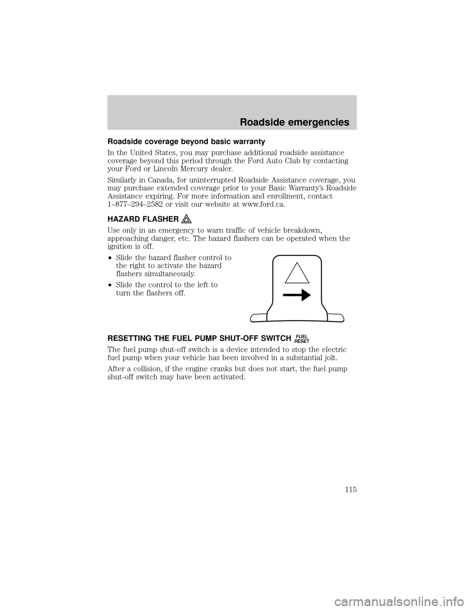
²Slide the hazard flasher control to
the right to activate the hazard
flashers simultaneously.
²Slide the control to the left to
turn the flashers off.
RESETTING THE FUEL PUMP SHUT-OFF SWITCH
FUEL
RESET
The fuel pump shut-off switch is a device intended to stop the electric
fuel pump when your vehicle has been involved in a substantial jolt.
After a collision, if the engine cranks but does not start, the fuel pump
shut-off switch may have been activated.
Roadside emergencies
115
Page 116 of 216
²Right side of the trunk behind the
trunk liner.
²Driver's foot well, behind the kick
panel.
The fuel pump shut-off switch, depending on application, is located on
the right side of the trunk behind the trunk liner or in the driver's foot
well, behind the kick panel.
Roadside emergencies
116
Page 117 of 216
Use the following procedure to reset the fuel pump shut-off switch.
1. Turn the ignition to the OFF position.
2. Check the fuel system for leaks.
3. If no fuel leak is apparent, reset the fuel pump shut-off switch by
pushing in on the reset button.
4. Turn the ignition to the ON position. Pause for a few seconds and
return the key to the OFF position.
5. Make a further check for leaks in the fuel system.
FUSES AND RELAYS
Fuses
If electrical components in the
vehicle are not working, a fuse may
have blown. Blown fuses are
identified by a broken wire within
the fuse. Check the appropriate
fuses before replacing any electrical
components.
NOTE:Always replace a fuse with one that has the specified amperage
rating. Using a fuse with a higher amperage rating can cause severe wire
damage and could start a fire.
15
Roadside emergencies
117
Page 123 of 216
Coupe
The high-current fuses are coded as follows.
Fuse/Relay
LocationFuse Amp
RatingPower Distribution Box
Description
FUEL INJ. 30A* Air Bags, Constant Control Relay
Module (PCM Relay), Generator
DEFOG 30A* Rear Window Defrost
MAIN 100A* Overall Circuit Protection
BTN 40A* Hazard, Stop, Door Lock, Tail,
Room and Horn Fuses of the I/P
Fuse Panel
ABS 60A* ABS Main Relay
COOLING FAN 40A* Constant Control Relay Module
(Cooling Fan)
OBD-II 10A* Data Link Connector (DLC),
Instrument Cluster
FUEL PUMP 20A** Constant Control Relay Module
(Fuel Pump)
HEAD RH 10A** Headlamps
HEAD LH 10A** Headlamps
* Fuse Link Cartridge **Fuse
USE THE DESIGNATED FUSES ONLY
FUEL INJ
30A
DEFOG
30A
MAIN
100A
COOLING FAN
40A (ABS)
60A BTN
40A
HEADLAMP
RELAY
FUEL PUMP 20AOBD-II 10A
HEAD RH 10A HEAD LH 10A
Roadside emergencies
123
Page 124 of 216
Sedan
The high-current fuses are coded as follows.
Fuse/Relay
LocationFuse Amp
RatingPower Distribution Box
Description
FUEL INJ. 30A* Air Bags, Engine Controls,
Generator
DEFOG 30A* Rear Window Defrost
MAIN 100A* Charging System, BTN, Cooling
Fan, Fuel Pump, OBD-II, ABS
Fuses, Ignition Switch, Headlamps
BTN 40A* Hazard
ABS 60A* ABS Main Relay
COOLING FAN 40A* Constant Control Relay Module
OBD-II 10A** Data Link Connector (DLC),
Instrument Cluster
FUEL PUMP 20A** Engine Controls
HEAD RH 10A** Headlamps
HEAD LH 10A** Headlamps
* Fuse Link Cartridge ** Fuse
USE THE DESIGNATED FUSES ONLY
FUEL INJ
30A
DEFOG
30A
MAIN
100A
COOLING FAN
40A (ABS)
60A BTN
40A
HEADLAMP
RELAY
FUEL PUMP 20AOBD-II 10A
HEAD RH 10A HEAD LH 10A
Roadside emergencies
124
Page 168 of 216

The flow of fuel through a fuel pump nozzle can produce static
electricity, which can cause a fire if fuel is pumped into an
ungrounded fuel container.
Use the following guidelines to avoid static build-up when filling an
ungrounded fuel container:
²Place approved fuel container on the ground.
²DO NOT fill a fuel container while it is in the vehicle (including the
cargo area).
²Keep the fuel pump nozzle in contact with the fuel container while
filling.
²DO NOT use a device that would hold the fuel pump handle in the fill
position.
Fuel Filler Cap
Your fuel tank filler cap has an indexed design with a 1/8 turn on/off
feature.
When fueling your vehicle:
1. Turn the engine off.
2. Carefully turn the filler cap counterclockwise 1/8 of a turn until it
stops.
3. Pull to remove the cap from the fuel filler pipe.
4. To install the cap, align the tabs on the cap with the notches on the
filler pipe.
5. Turn the filler cap clockwise 1/8 of a turn until it stops.
The ªCheck Fuel Capº (if equipped) light illuminates when the ignition is
turned to the ON position. It will also illuminate when the fuel filler cap
is not properly installed. Proper fuel filler cap installation is checked
automatically as the vehicle is driven, but not until after some fuel is
used (fuel guage drops below full). Once the fuel filler cap is properly
secured, the ªCheck Fuel Capº light will turn off after a short period of
driving.
If you must replace the fuel filler cap, replace it with a fuel filler
cap that is designed for your vehicle. The customer warranty may
be void for any damage to the fuel tank or fuel system if the
correct genuine Ford or Motorcraft fuel filler cap is not used.
Maintenance and care
168