2001 DODGE TOWN AND COUNTRY door
[x] Cancel search: doorPage 2 of 2321
INTRODUCTION
TABLE OF CONTENTS
page page
VEHICLE SAFETY CERTIFICATION LABEL
DESCRIPTION............................1
VEHICLE IDENTIFICATION NUMBER
DESCRIPTION............................1
VECI LABEL
DESCRIPTION............................3
BODY CODE PLATE
DESCRIPTION............................3
INTERNATIONAL SYMBOLS
DESCRIPTION............................4FASTENER IDENTIFICATION
DESCRIPTION............................5
FASTENER USAGE
DESCRIPTION............................5
METRIC SYSTEM
DESCRIPTION............................8
TORQUE REFERENCES
DESCRIPTION...........................10
VEHICLE SAFETY
CERTIFICATION LABEL
DESCRIPTION
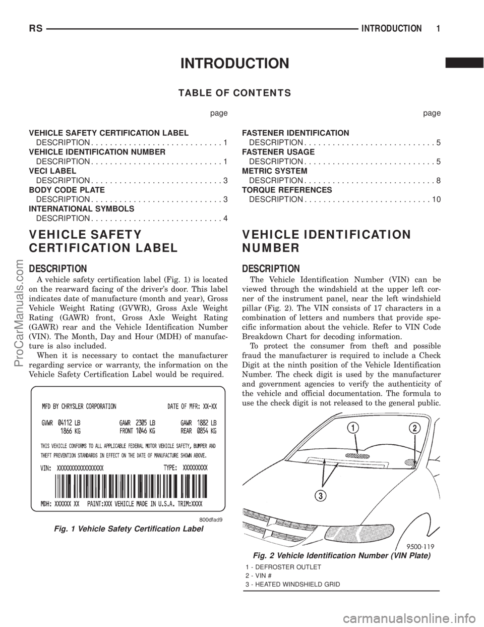
A vehicle safety certification label (Fig. 1) is located
on the rearward facing of the driver's door. This label
indicates date of manufacture (month and year), Gross
Vehicle Weight Rating (GVWR), Gross Axle Weight
Rating (GAWR) front, Gross Axle Weight Rating
(GAWR) rear and the Vehicle Identification Number
(VIN). The Month, Day and Hour (MDH) of manufac-
ture is also included.
When it is necessary to contact the manufacturer
regarding service or warranty, the information on the
Vehicle Safety Certification Label would be required.
VEHICLE IDENTIFICATION
NUMBER
DESCRIPTION
The Vehicle Identification Number (VIN) can be
viewed through the windshield at the upper left cor-
ner of the instrument panel, near the left windshield
pillar (Fig. 2). The VIN consists of 17 characters in a
combination of letters and numbers that provide spe-
cific information about the vehicle. Refer to VIN Code
Breakdown Chart for decoding information.
To protect the consumer from theft and possible
fraud the manufacturer is required to include a Check
Digit at the ninth position of the Vehicle Identification
Number. The check digit is used by the manufacturer
and government agencies to verify the authenticity of
the vehicle and official documentation. The formula to
use the check digit is not released to the general public.
Fig. 1 Vehicle Safety Certification Label
Fig. 2 Vehicle Identification Number (VIN Plate)
1 - DEFROSTER OUTLET
2 - VIN #
3 - HEATED WINDSHIELD GRID
RSINTRODUCTION1
ProCarManuals.com
Page 21 of 2321
VEHICLE SAFETY
CERTIFICATION LABEL
DESCRIPTION
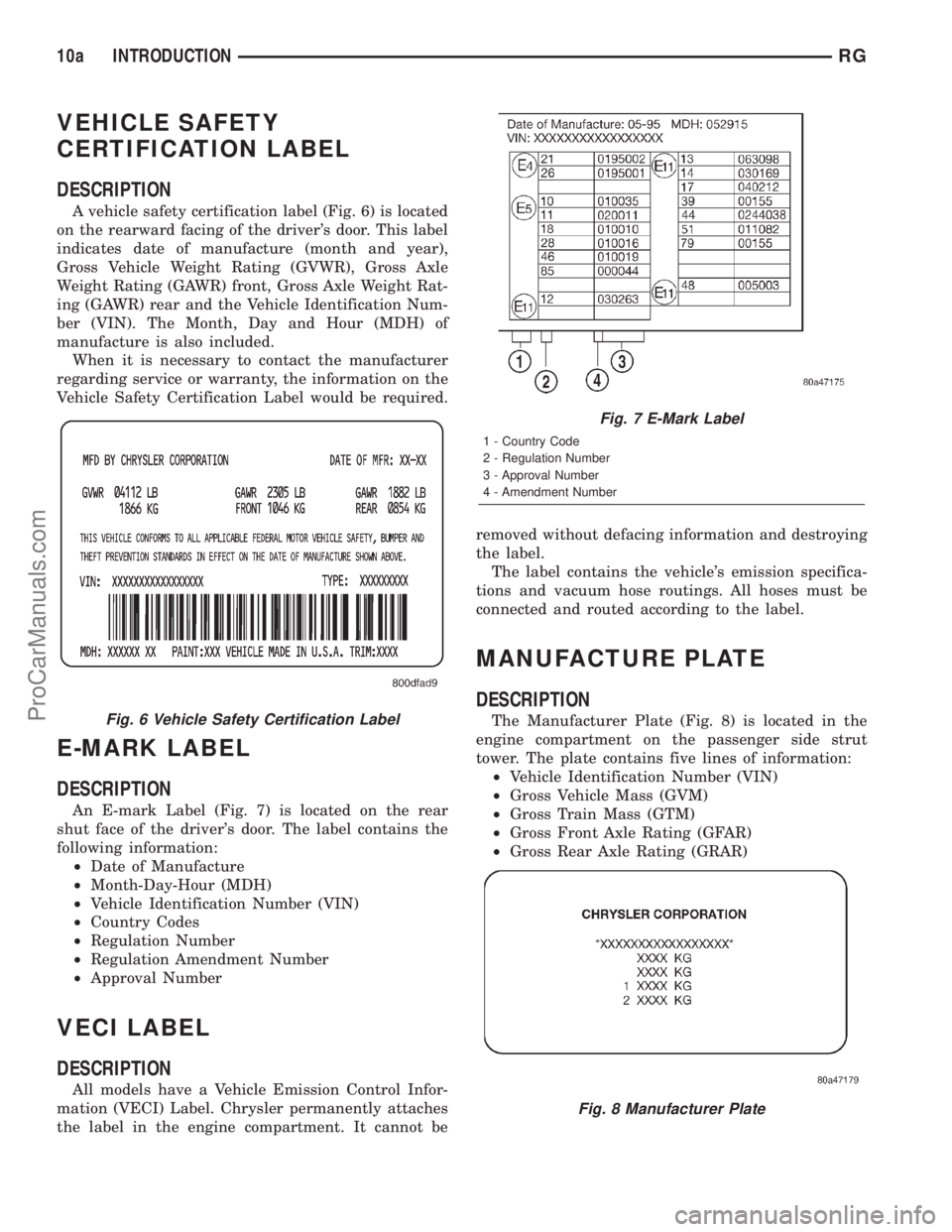
A vehicle safety certification label (Fig. 6) is located
on the rearward facing of the driver's door. This label
indicates date of manufacture (month and year),
Gross Vehicle Weight Rating (GVWR), Gross Axle
Weight Rating (GAWR) front, Gross Axle Weight Rat-
ing (GAWR) rear and the Vehicle Identification Num-
ber (VIN). The Month, Day and Hour (MDH) of
manufacture is also included.
When it is necessary to contact the manufacturer
regarding service or warranty, the information on the
Vehicle Safety Certification Label would be required.
E-MARK LABEL
DESCRIPTION
An E-mark Label (Fig. 7) is located on the rear
shut face of the driver's door. The label contains the
following information:
²Date of Manufacture
²Month-Day-Hour (MDH)
²Vehicle Identification Number (VIN)
²Country Codes
²Regulation Number
²Regulation Amendment Number
²Approval Number
VECI LABEL
DESCRIPTION
All models have a Vehicle Emission Control Infor-
mation (VECI) Label. Chrysler permanently attaches
the label in the engine compartment. It cannot beremoved without defacing information and destroying
the label.
The label contains the vehicle's emission specifica-
tions and vacuum hose routings. All hoses must be
connected and routed according to the label.
MANUFACTURE PLATE
DESCRIPTION
The Manufacturer Plate (Fig. 8) is located in the
engine compartment on the passenger side strut
tower. The plate contains five lines of information:
²Vehicle Identification Number (VIN)
²Gross Vehicle Mass (GVM)
²Gross Train Mass (GTM)
²Gross Front Axle Rating (GFAR)
²Gross Rear Axle Rating (GRAR)Fig. 6 Vehicle Safety Certification Label
Fig. 7 E-Mark Label
1 - Country Code
2 - Regulation Number
3 - Approval Number
4 - Amendment Number
Fig. 8 Manufacturer Plate
10a INTRODUCTIONRG
ProCarManuals.com
Page 24 of 2321
FLUID TYPES
DESCRIPTION
E-85 GENERAL INFORMATION
The information in this section is for Flexible Fuel
Vehicles (FFV) only. These vehicles can be identified
by the unique Fuel Filler Door Label that states
Ethanol (E-85) or Unleaded Gasoline Only. This sec-
tion only covers those subjects that are unique to
these vehicles. Please refer to the other sections of
this manual for information on features that are
common between Flexible Fuel and gasoline only
powered vehicles.
ETHANOL FUEL (E-85)
E-85 is a mixture of approximately 85% fuel etha-
nol and 15% unleaded gasoline.
WARNING: Ethanol vapors are extremely flammable
and could cause serious personal injury. Never
have any smoking materials lit in or near the vehi-
cle when removing the fuel filler tube cap (gas cap)
or filling the tank. Do not use E-85 as a cleaning
agent and never use it near an open flame.
FUEL REQUIREMENTS
The vehicle will operate on both unleaded gasoline
with an octane rating of 87, or E-85 fuel, or any mix-
ture of these two.
For best results, a refueling pattern that alternates
between E-85 and unleaded gasoline should be
avoided. When you do switch fuels, it is recom-
mended that
²you do not switch when the fuel gauge indicates
less than 1/4 full
²you do not add less than 5 gallons when refuel-
ing
²you operate the vehicle immediately after refuel-
ing for a period of at least 5 minutes
Observing these precautions will avoid possible
hard starting and/or significant deterioration in
driveability during warm up.
FFV STARTING
The characteristics of E-85 fuel make it unsuitable
for use when ambient temperatures fall below 0ÉF. In
the range of 0ÉF to 32ÉF, you may experience an
increase in the time it takes for your engine to start,
and a deterioration in driveability (sags and/or hesi-
tations) until the engine is fully warmed up.
CRUISING RANGE
Because E-85 fuel contains less energy per gallon
than gasoline, you will experience an increase in fuelconsumption. You can expect your MPG and your
driving range to decrease by about 30% compared to
gasoline operation.
ENGINE OIL
WARNING: NEW OR USED ENGINE OIL CAN BE
IRRITATING TO THE SKIN. AVOID PROLONGED OR
REPEATED SKIN CONTACT WITH ENGINE OIL.
CONTAMINANTS IN USED ENGINE OIL, CAUSED BY
INTERNAL COMBUSTION, CAN BE HAZARDOUS TO
YOUR HEALTH. THOROUGHLY WASH EXPOSED
SKIN WITH SOAP AND WATER. DO NOT WASH
SKIN WITH GASOLINE, DIESEL FUEL, THINNER, OR
SOLVENTS, HEALTH PROBLEMS CAN RESULT. DO
NOT POLLUTE, DISPOSE OF USED ENGINE OIL
PROPERLY. CONTACT YOUR DEALER OR GOVERN-
MENT AGENCY FOR LOCATION OF COLLECTION
CENTER IN YOUR AREA.
API SERVICE GRADE CERTIFIED
Use an engine oil that is API Service Grade Certi-
fied. MOPARtprovides engine oils that conform to
this service grade.
SAE VISCOSITY
An SAE viscosity grade is used to specify the vis-
cosity of engine oil. Use only engine oils with multi-
ple viscosities such as 5W-30 or 10W-30. These are
specified with a dual SAE viscosity grade which indi-
cates the cold-to-hot temperature viscosity range.
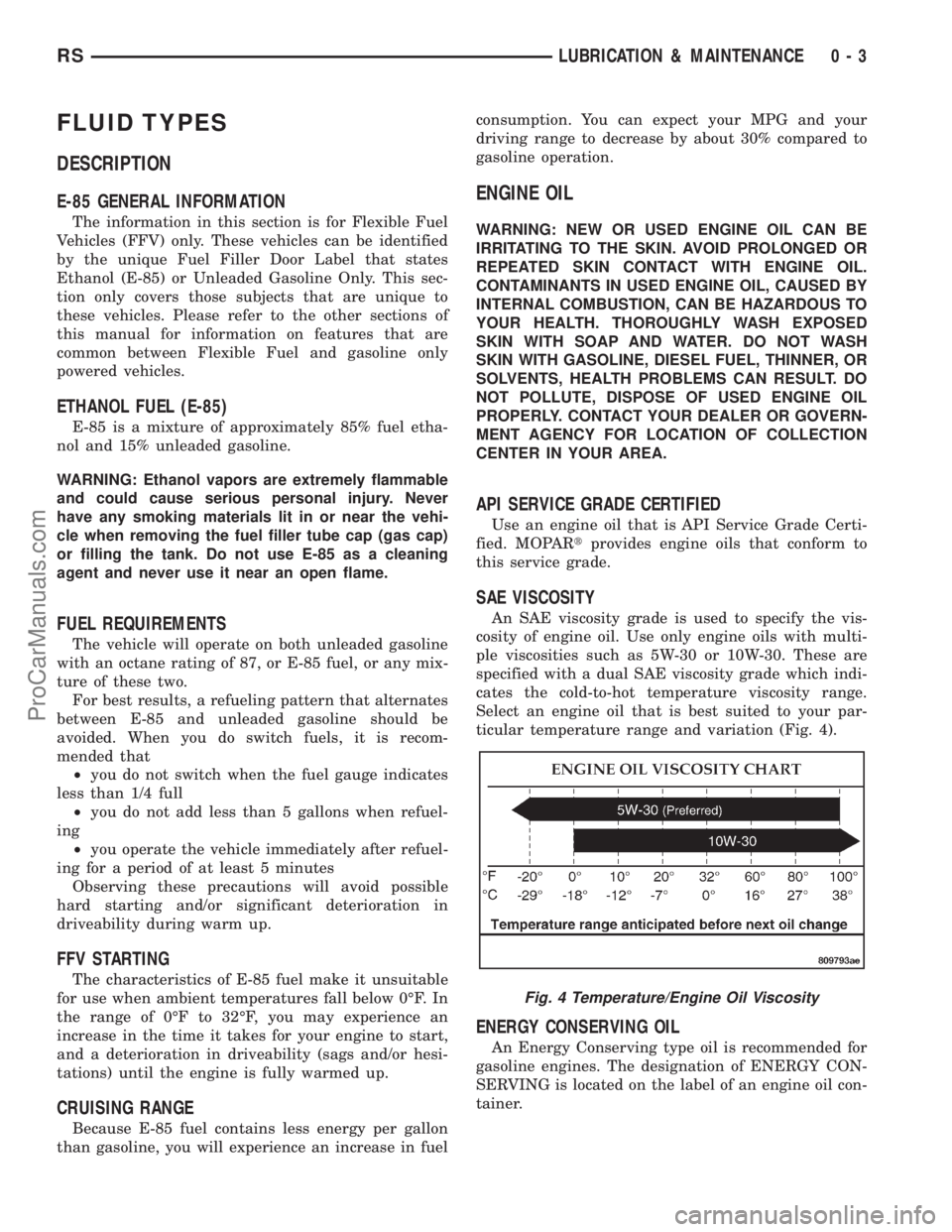
Select an engine oil that is best suited to your par-
ticular temperature range and variation (Fig. 4).
ENERGY CONSERVING OIL
An Energy Conserving type oil is recommended for
gasoline engines. The designation of ENERGY CON-
SERVING is located on the label of an engine oil con-
tainer.
Fig. 4 Temperature/Engine Oil Viscosity
RSLUBRICATION & MAINTENANCE0-3
ProCarManuals.com
Page 211 of 2321
(1) Grasp the exposed section of the front parking
brake cable and pull rearward on it. While holding
the park brake in this position, install a pair of lock-
ing pliers on the front parking brake cable just rear-
ward of the second body outrigger bracket (Fig. 76).
(2) Install the equalizer on the front parking brake
cable.
(3) Install the left rear and intermediate park
brake cable in the correct location on the parking
brake cable equalizer (Fig. 77).
(4) Remove the locking pliers from the front park-
ing brake cable. This will allow the adjuster in the
park brake lever (pedal) mechanism to tension the
park brake cables.
(5) Apply and release the parking brake lever
(pedal) one time. This will seat the parking brake
cables and allow the auto adjuster in the parking
brake lever (pedal) mechanism to correctly tension
the parking brake cables.
LEVER - PARKING BRAKE
REMOVAL
(1) Manually release the automatic self-adjusting
mechanism tension of the parking brake lever (pedal)
assembly. (Refer to 5 - BRAKES/PARKING BRAKE -
STANDARD PROCEDURE).
(2) Disconnect negative (ground) cable from the
battery and isolate cable from battery terminal.
(3) Remove sill scuff plate from left door sill.
(4) Remove the left side kick panel.
(5) Remove the silencer panel under the instru-
ment panel.
(6) Remove the steering column cover from the
lower instrument panel.
(7) Remove the reinforcement from the lower
instrument panel.
(8) Remove the front parking brake cable from the
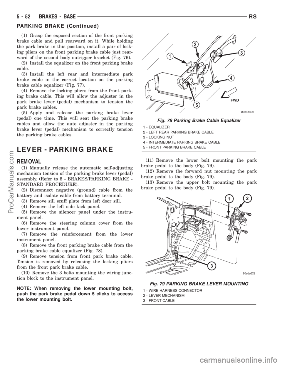
parking brake cable equalizer (Fig. 78).
(9) Remove tension from front park brake cable.
Tension is removed by releasing the locking pliers
from the front park brake cable.
(10) Remove the 3 bolts mounting the wiring junc-
tion block to the instrument panel.
NOTE: When removing the lower mounting bolt,
push the park brake pedal down 5 clicks to access
the lower mounting bolt.(11) Remove the lower bolt mounting the park
brake pedal to the body (Fig. 79).
(12) Remove the forward nut mounting the park
brake pedal to the body (Fig. 79).
(13) Remove the upper bolt mounting the park
brake pedal to the body (Fig. 79).
Fig. 78 Parking Brake Cable Equalizer
1 - EQUALIZER
2 - LEFT REAR PARKING BRAKE CABLE
3 - LOCKING NUT
4 - INTERMEDIATE PARKING BRAKE CABLE
5 - FRONT PARKING BRAKE CABLE
Fig. 79 PARKING BRAKE LEVER MOUNTING
1 - WIRE HARNESS CONNECTOR
2 - LEVER MECHANISM
3 - FRONT CABLE
5 - 52 BRAKES - BASERS
PARKING BRAKE (Continued)
ProCarManuals.com
Page 212 of 2321

(14) Pull downward on front park brake cable
while rotating park brake pedal mechanism out from
behind junction block.
(15) Remove park brake pedal release link from
park brake mechanism.
(16) Remove the warning lamp ground switch con-
nector from the park brake pedal mechanism (Fig.
79).
(17) Remove front park brake cable button from
park brake pedal mechanism. Tap end housing for
front park brake cable out of park brake pedal mech-
anism.
INSTALLATION
(1) Install park brake cable end housing into park
brake pedal mechanism.
(2) Install cable retainer onto the park brake cable
strand and then install retainer into pedal bracket.
(3) Install cable strand button into the clevis on
the park brake pedal mechanism.
(4) Install wiring harness connector on warning
indicator lamp ground switch.
(5) Install the park brake release rod on the
release mechanism of the park brake pedal.
(6) Position the park brake pedal mechanism into
its installed position on the body of the vehicle.
(7) Loosely install the top bolt mounting the park
brake pedal mechanism to the body (Fig. 79).
(8) Loosely install the forward nut mounting the
park brake pedal mechanism to the body (Fig. 79).
(9) Loosely install the lower bolt mounting the
park brake pedal mechanism to the body (Fig. 79).
(10) Tighten pedal mechanism attaching bolts and
nut to 28 N´m (250 in. lbs.).
(11) Verify that the park brake pedal is in the fully
released (full up) position.
(12) Raise vehicle.
(13) Install the front park brake cable on the park
brake cable equalizer (Fig. 78).
NOTE: If the original lever assembly is being used,
the lever mechanism auto adjuster spring tension
will need to be reset. (Refer to 5 - BRAKES/PARK-
ING BRAKE - STANDARD PROCEDURE)
(14) Lower vehicle.
(15) Remove the lock-out pin (if a new lever has
been installed) from the automatic cable adjuster on
the park brake pedal mechanism.
(16) Install the electrical junction block on the
instrument panel.
(17) Install the reinforcement on the lower instru-
ment panel.
(18) Install the steering column lower cover on the
lower instrument panel.(19) Install the silencer panel under the instru-
ment panel.
(20) Install the left side kick panel.
(21) Install the sill scuff plate on the lower sill of
the left door.
(22) Install the negative (ground) cable on the bat-
tery.
(23) Cycle the park brake pedal one time. This will
seat the park brake cables and will allow the auto-
matic self adjuster to properly tension the park brake
cables.
SHOES - PARKING BRAKE
REMOVAL
(1) Set the parking brake.The parking brake is
set to keep the hub/bearing and axle shaft from
rotating when loosening the hub nut.
(2) Raise vehicle. (Refer to LUBRICATION &
MAINTENANCE/HOISTING - STANDARD PROCE-
DURE).
(3) Remove the wheel and tire assembly.
(4) Remove the cotter pin and nut retainer (Fig.
80) from the stub shaft of the outer C/V joint.
(5) Remove the spring washer (Fig. 81) from the
stub shaft of the outer C/V joint.
(6) Remove the hub nut and washer (Fig. 82) from
the stub shaft of the outer C/V joint.
(7) Release the parking brake.
Fig. 80 Cotter Pin And Nut Retainer
1 - CALIPER
2 - COTTER PIN
3 - ROTOR
4 - NUT RETAINER
5 - OUTER C/V JOINT
RSBRAKES - BASE5-53
LEVER (Continued)
ProCarManuals.com
Page 220 of 2321
(18) Road test the vehicle to ensure proper func-
tion of the vehicle's brake system.
CABLES - PARKING BRAKE
REMOVAL - PARKING BRAKE CABLE (FRONT)
(1) Raise vehicle on jackstands or centered on a
hoist. (Refer to LUBRICATION & MAINTENANCE/
HOISTING - STANDARD PROCEDURE).
(2) Manually release the automatic self-adjusting
mechanism tension of the parking brake lever (pedal)
assembly. (Refer to 5 - BRAKES - STANDARD PRO-
CEDURE).
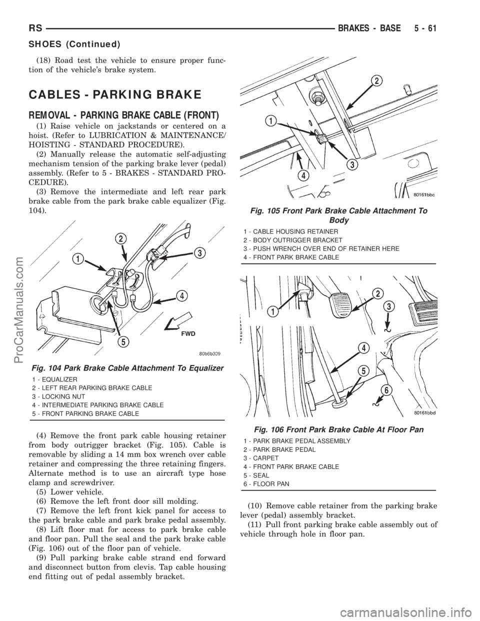
(3) Remove the intermediate and left rear park
brake cable from the park brake cable equalizer (Fig.
104).
(4) Remove the front park cable housing retainer
from body outrigger bracket (Fig. 105). Cable is
removable by sliding a 14 mm box wrench over cable
retainer and compressing the three retaining fingers.
Alternate method is to use an aircraft type hose
clamp and screwdriver.
(5) Lower vehicle.
(6) Remove the left front door sill molding.
(7) Remove the left front kick panel for access to
the park brake cable and park brake pedal assembly.
(8) Lift floor mat for access to park brake cable
and floor pan. Pull the seal and the park brake cable
(Fig. 106) out of the floor pan of vehicle.
(9) Pull parking brake cable strand end forward
and disconnect button from clevis. Tap cable housing
end fitting out of pedal assembly bracket.(10) Remove cable retainer from the parking brake
lever (pedal) assembly bracket.
(11) Pull front parking brake cable assembly out of
vehicle through hole in floor pan.
Fig. 104 Park Brake Cable Attachment To Equalizer
1 - EQUALIZER
2 - LEFT REAR PARKING BRAKE CABLE
3 - LOCKING NUT
4 - INTERMEDIATE PARKING BRAKE CABLE
5 - FRONT PARKING BRAKE CABLE
Fig. 105 Front Park Brake Cable Attachment To
Body
1 - CABLE HOUSING RETAINER
2 - BODY OUTRIGGER BRACKET
3 - PUSH WRENCH OVER END OF RETAINER HERE
4 - FRONT PARK BRAKE CABLE
Fig. 106 Front Park Brake Cable At Floor Pan
1 - PARK BRAKE PEDAL ASSEMBLY
2 - PARK BRAKE PEDAL
3 - CARPET
4 - FRONT PARK BRAKE CABLE
5 - SEAL
6 - FLOOR PAN
RSBRAKES - BASE5-61
SHOES (Continued)
ProCarManuals.com
Page 309 of 2321
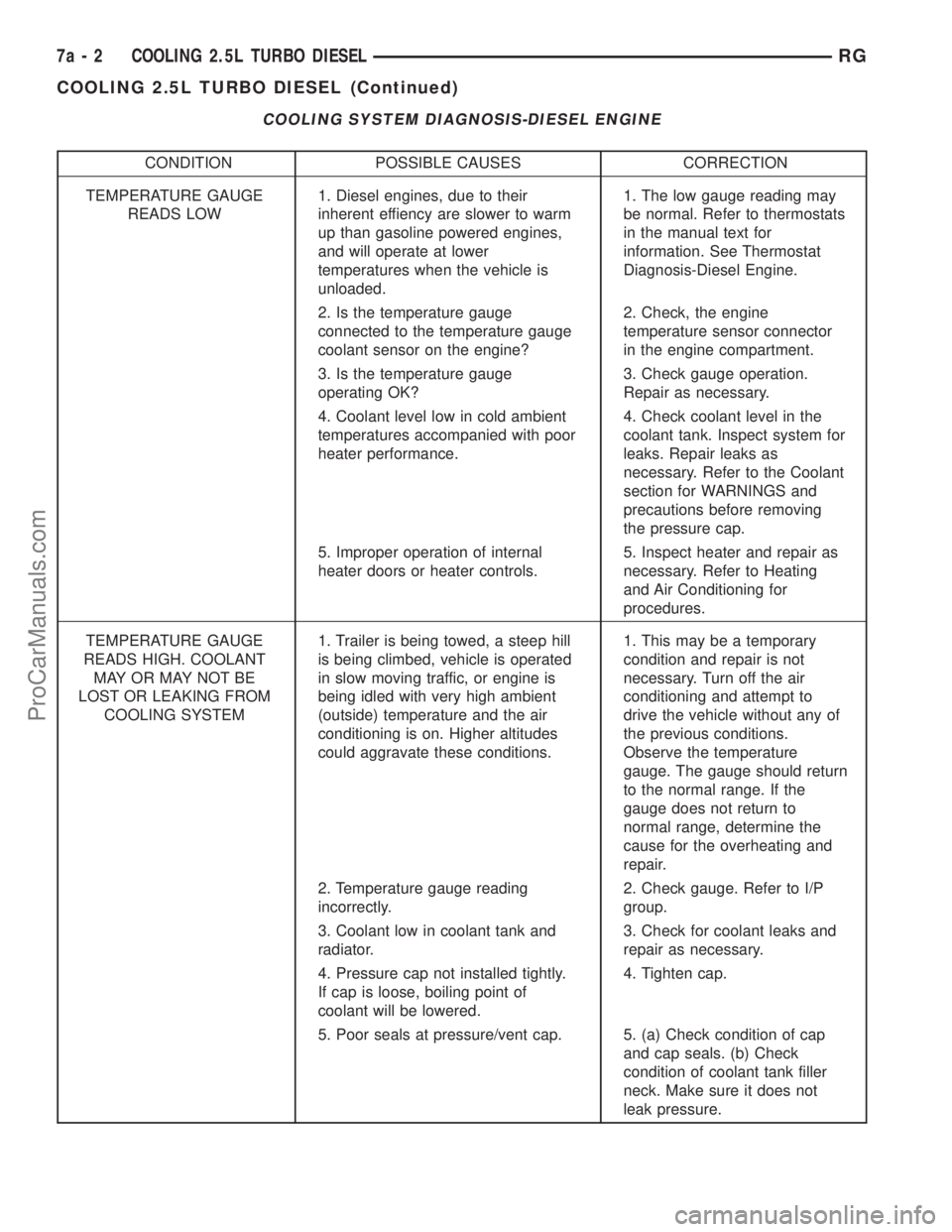
COOLING SYSTEM DIAGNOSIS-DIESEL ENGINE
CONDITION POSSIBLE CAUSES CORRECTION
TEMPERATURE GAUGE
READS LOW1. Diesel engines, due to their
inherent effiency are slower to warm
up than gasoline powered engines,
and will operate at lower
temperatures when the vehicle is
unloaded.1. The low gauge reading may
be normal. Refer to thermostats
in the manual text for
information. See Thermostat
Diagnosis-Diesel Engine.
2. Is the temperature gauge
connected to the temperature gauge
coolant sensor on the engine?2. Check, the engine
temperature sensor connector
in the engine compartment.
3. Is the temperature gauge
operating OK?3. Check gauge operation.
Repair as necessary.
4. Coolant level low in cold ambient
temperatures accompanied with poor
heater performance.4. Check coolant level in the
coolant tank. Inspect system for
leaks. Repair leaks as
necessary. Refer to the Coolant
section for WARNINGS and
precautions before removing
the pressure cap.
5. Improper operation of internal
heater doors or heater controls.5. Inspect heater and repair as
necessary. Refer to Heating
and Air Conditioning for
procedures.
TEMPERATURE GAUGE
READS HIGH. COOLANT
MAY OR MAY NOT BE
LOST OR LEAKING FROM
COOLING SYSTEM1. Trailer is being towed, a steep hill
is being climbed, vehicle is operated
in slow moving traffic, or engine is
being idled with very high ambient
(outside) temperature and the air
conditioning is on. Higher altitudes
could aggravate these conditions.1. This may be a temporary
condition and repair is not
necessary. Turn off the air
conditioning and attempt to
drive the vehicle without any of
the previous conditions.
Observe the temperature
gauge. The gauge should return
to the normal range. If the
gauge does not return to
normal range, determine the
cause for the overheating and
repair.
2. Temperature gauge reading
incorrectly.2. Check gauge. Refer to I/P
group.
3. Coolant low in coolant tank and
radiator.3. Check for coolant leaks and
repair as necessary.
4. Pressure cap not installed tightly.
If cap is loose, boiling point of
coolant will be lowered.4. Tighten cap.
5. Poor seals at pressure/vent cap. 5. (a) Check condition of cap
and cap seals. (b) Check
condition of coolant tank filler
neck. Make sure it does not
leak pressure.
7a - 2 COOLING 2.5L TURBO DIESELRG
COOLING 2.5L TURBO DIESEL (Continued)
ProCarManuals.com
Page 338 of 2321
AUDIO
TABLE OF CONTENTS
page page
AUDIO
DESCRIPTION............................1
OPERATION.............................1
DIAGNOSIS AND TESTING..................1
ANTENNA BODY & CABLE
DESCRIPTION............................3
OPERATION.............................3
DIAGNOSIS AND TESTING..................3
REMOVAL...............................4
INSTALLATION............................4
CD CHANGER
DESCRIPTION............................6
OPERATION.............................6
REMOVAL...............................6
INSTALLATION............................6
CHOKE
DIAGNOSIS AND TESTING..................6
D-PILLAR SPEAKER
REMOVAL...............................6
INSTALLATION............................7
DASH PANEL SPEAKER
REMOVAL...............................7INSTALLATION............................7
DOOR MOUNTED SPEAKER
REMOVAL...............................7
INSTALLATION............................7
QUARTER PANEL SPEAKER
REMOVAL...............................8
INSTALLATION............................8
RADIO
DIAGNOSIS AND TESTING..................8
REMOVAL...............................9
INSTALLATION............................9
RADIO NOISE SUPPRESSION COMPONENTS
DESCRIPTION............................9
OPERATION.............................9
REMOTE SWITCHES
DESCRIPTION...........................10
OPERATION.............................10
DIAGNOSIS AND TESTING.................11
REMOVAL..............................11
INSTALLATION...........................12
AUDIO
DESCRIPTION
There are four different system combinations avail-
able on the RS models. The available radio options
are:
²AM/FM Cassette
²AM/FM Compact Disc with Compact Disc
Changer
²AM/FM Cassette with single Compact Disc
Player
²AM/FM Cassette with Compact Disc Changer
All factory installed radio receivers are stereo Elec-
tronically Tuned Radios (ETR) and include and elec-
tronic digital clock function.
OPERATION
Operating instructions for the factory installed
audio systems can be found in the Owner's Manual
provided with this vehicle.
DIAGNOSIS AND TESTING
WARNING:
ON VEHICLES EQUIPPED WITH AIRBAGS, REFER
TO ELECTRICAL, RESTRAINTS BEFORE ATTEMPT-
ING ANY STEERING WHEEL, STEERING COLUMN,
OR INSTRUMENT PANEL COMPONENT DIAGNOSIS
OR SERVICE. FAILURE TO TAKE THE PROPER
PRECAUTIONS COULD RESULT IN ACCIDENTAL
AIRBAG DEPLOYMENT AND POSSIBLE PERSONAL
INJURY.
RSAUDIO8A-1
ProCarManuals.com