2001 DODGE TOWN AND COUNTRY steering
[x] Cancel search: steeringPage 229 of 2321
CAUTION: If welding work is to be performed on the
vehicle, using an electric arc welder, the CAB con-
nector should be disconnected during the welding
operation.
CAUTION: Many components of the ABS System
are not serviceable and must be replaced as an
assembly. Do not disassemble any component
which is not designed to be serviced.
CAUTION: Only the recommended jacking or hoist-
ing positions for this vehicle are to be used when-
ever it is necessary to lift a vehicle. Failure to raise
a vehicle from the recommended locations could
result in lifting a vehicle by the hydraulic control
unit mounting bracket. Lifting a vehicle by the
hydraulic control unit mounting bracket will result
in damage to the mounting bracket and the hydrau-
lic control unit.
CAUTION: Brake fluid will damage painted surfaces.
If brake fluid is spilled on any painted surface,
wash off with water immediately.
STANDARD PROCEDURE - ANTILOCK BRAKE
SYSTEM BLEEDING
The base brake's hydraulic system must be bled
anytime air enters the hydraulic system. The ABS
though, particularly the ICU (HCU), should only be
bled when the HCU is replaced or removed from the
vehicle. The ABS must always be bled anytime it is
suspected that the HCU has ingested air. Under
most circumstances that require the bleeding of the
brakes hydraulic system, only the base brake
hydraulic system needs to be bled.
It is important to note that excessive air in the
brake system will cause a soft or spongy feeling
brake pedal.
During the brake bleeding procedure, be sure the
brake fluid level remains close to the FULL level in
the master cylinder fluid reservoir. Check the fluid
level periodically during the bleeding procedure and
add DOT 3 brake fluid as required.
The ABS must be bled as two independent braking
systems. The non-ABS portion of the brake systemwith ABS is to be bled the same as any non-ABS sys-
tem.
The ABS portion of the brake system must be bled
separately. Use the following procedure to properly
bleed the brake hydraulic system including the ABS.
BLEEDING
When bleeding the ABS system, the following
bleeding sequence must be followed to insure com-
plete and adequate bleeding.
(1) Make sure all hydraulic fluid lines are installed
and properly torqued.
(2) Connect the DRBIIItscan tool to the diagnos-
tics connector. The diagnostic connector is located
under the lower steering column cover to the left of
the steering column.
(3) Using the DRB, check to make sure the CAB
does not have any fault codes stored. If it does, clear
them using the DRB.
WARNING: WHEN BLEEDING THE BRAKE SYSTEM
WEAR SAFETY GLASSES. A CLEAR BLEED TUBE
MUST BE ATTACHED TO THE BLEEDER SCREWS
AND SUBMERGED IN A CLEAR CONTAINER FILLED
PART WAY WITH CLEAN BRAKE FLUID. DIRECT
THE FLOW OF BRAKE FLUID AWAY FROM YOUR-
SELF AND THE PAINTED SURFACES OF THE VEHI-
CLE. BRAKE FLUID AT HIGH PRESSURE MAY
COME OUT OF THE BLEEDER SCREWS WHEN
OPENED.
(4) Bleed the base brake system using the stan-
dard pressure or manual bleeding procedure. (Refer
to 5 - BRAKES - BASE - STANDARD PROCEDURE)
(5) Using the DRB, select ANTILOCK BRAKES,
followed by MISCELLANEOUS, then BLEED
BRAKES. Follow the instructions displayed. When
the scan tool displays TEST COMPLETED, discon-
nect the scan tool and proceed.
(6) Bleed the base brake system a second time.
Check brake fluid level in the reservoir periodically
to prevent emptying, causing air to enter the hydrau-
lic system.
(7) Fill the master cylinder reservoir to the full
level.
(8) Test drive the vehicle to be sure the brakes are
operating correctly and that the brake pedal does not
feel spongy.
5 - 70 BRAKES - ABSRS
BRAKES - ABS (Continued)
ProCarManuals.com
Page 230 of 2321

SPECIFICATIONS
SPECIFICATIONS - ABS FASTENER TORQUE
(Refer to 5 - BRAKES - BASE - SPECIFICA-
TIONS)
TONE WHEEL RUNOUT
DESCRIPTION SPECIFICATION
Front Tone Wheel
Maximum Runout0.15 mm (0.006 in.)
Rear Tone Wheel
Maximum Runout0.15 mm (0.006 in.)
WHEEL SPEED SENSOR AIR GAP
DESCRIPTION SPECIFICATION
Front Sensor0.35 ± 1.20 mm
0.014 ± 0.047 in.
Rear Sensor0.40 ± 1.20 mm
0.016 ± 0.047 in.
FRONT WHEEL SPEED
SENSOR
REMOVAL - WHEEL SPEED SENSOR (FRONT)
(1) Raise vehicle. (Refer to LUBRICATION &
MAINTENANCE/HOISTING - STANDARD PROCE-
DURE)
(2) Remove the tire and wheel assembly.
(3) Remove the sensor cable routing clamp screws.
CAUTION: When disconnecting the wheel speed
sensor from vehicle wiring harness, be careful not
to damage pins on connector
(4) Remove speed sensor cable grommets from
intermediate bracket on strut.
(5) Disconnect speed sensor cable from vehicle wir-
ing harness behind fender well shield.
(6) Remove the wheel speed sensor head mounting
bolt (Fig. 1).
(7) Remove sensor head from steering knuckle. If
sensor has seized due to corrosion,DO NOT USE
PLIERS ON SENSOR HEAD.Use a hammer and a
punch and tap edge of sensor ear, rocking the sensor
side-to-side until free.
(8) Remove front wheel speed sensor from vehicle.
INSTALLATION - WHEEL SPEED SENSOR
(FRONT)
CAUTION: Proper installation of wheel speed sen-
sor cables is critical to continued system operation.
Be sure that cables are installed in retainers. Fail-
ure to install cables in retainers as shown in this
section may result in contact with moving parts and
over extension of cables, resulting in an open cir-
cuit.
(1) Connect the front wheel speed sensor cable to
the vehicle wiring harness connector. Be sure speed
sensor cable connector is fully seated and locked into
vehicle wiring harness connector.
(2) Install the bolts attaching the routing clamps
to the body of the vehicle. Tighten the bolts to a
torque of 11 N´m (95 in. lbs.).
(3) Insert speed sensor cable grommets into inter-
mediate bracket on strut.
(4) Install the wheel speed sensor head mounting
bolt (Fig. 1). Tighten the bolt to a torque of 12 N´m
(105 in. lbs.)
(5) Install the wheel and tire assembly on vehicle.
(6) Lower vehicle.
(7) Road test vehicle to ensure proper operation of
the base and ABS brake systems.
Fig. 1 Front Wheel Speed Sensor Attaching Bolt
1 - MOUNTING BOLT
2 - WHEEL SPEED SENSOR
3 - DRIVESHAFT
4 - TONE WHEEL
5 - STEERING KNUCKLE
RSBRAKES - ABS5-71
BRAKES - ABS (Continued)
ProCarManuals.com
Page 235 of 2321
REMOVAL - ICU
(1) Disconnect the negative (ground) cable from
the battery and isolate cable.
(2) Remove the battery shield.
(3) Remove the battery (Refer to 8 - ELECTRI-
CAL/BATTERY SYSTEM/BATTERY - REMOVAL).
(4) Disconnect the vacuum hose connector at the
tank built into the battery tray.
(5) Remove the screw securing the engine coolant
filler neck to the battery tray.
(6) Remove the battery tray (Refer to 8 - ELEC-
TRICAL/BATTERY SYSTEM/TRAY - REMOVAL).
(7) Using a brake pedal depressor, move and lock
the brake pedal to a position past the first inch of
pedal travel.This will prevent brake fluid from
draining out of the master cylinder once the
brake tubes are removed from the HCU.
CAUTION: Do not apply a 12±volt power source to
any terminals of the 24-way CAB connector when
disconnected.
(8) Disconnect the wiring harness connector from
the speed control servo.
(9) Remove the speed control servo mounting nuts
and move the servo out of the way.
(10) Disconnect the 24±way connector from the
CAB. To disconnect the 24±way connector, grasp the
lock on the 24±way connector and pull it as far up as
possible. This will unlock the 24±way connector from
the socket on the CAB.
CAUTION: Before removing the brake tubes from
the HCU, the HCU must be thoroughly cleaned. This
must be done to prevent dirt particles from falling
into the ports of HCU or entering the brake tubes.
(11) Thoroughly clean all surfaces of the ICU and
brake tube nuts. Use only a solvent such as Mopart
Brake Parts Cleaner or equivalent to clean the ICU.
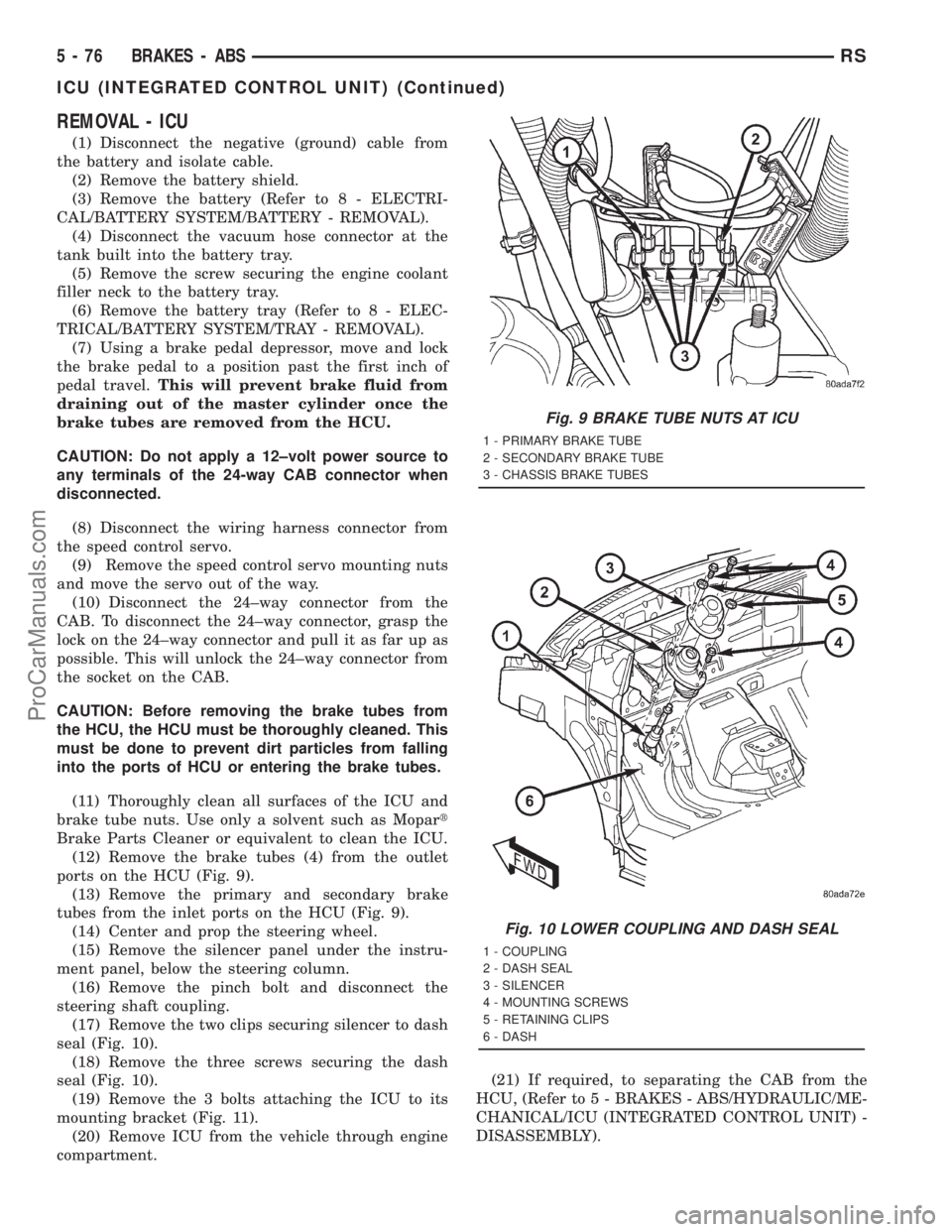
(12) Remove the brake tubes (4) from the outlet
ports on the HCU (Fig. 9).
(13) Remove the primary and secondary brake
tubes from the inlet ports on the HCU (Fig. 9).
(14) Center and prop the steering wheel.
(15) Remove the silencer panel under the instru-
ment panel, below the steering column.
(16) Remove the pinch bolt and disconnect the
steering shaft coupling.
(17) Remove the two clips securing silencer to dash
seal (Fig. 10).
(18) Remove the three screws securing the dash
seal (Fig. 10).
(19) Remove the 3 bolts attaching the ICU to its
mounting bracket (Fig. 11).
(20) Remove ICU from the vehicle through engine
compartment.(21) If required, to separating the CAB from the
HCU, (Refer to 5 - BRAKES - ABS/HYDRAULIC/ME-
CHANICAL/ICU (INTEGRATED CONTROL UNIT) -
DISASSEMBLY).
Fig. 9 BRAKE TUBE NUTS AT ICU
1 - PRIMARY BRAKE TUBE
2 - SECONDARY BRAKE TUBE
3 - CHASSIS BRAKE TUBES
Fig. 10 LOWER COUPLING AND DASH SEAL
1 - COUPLING
2 - DASH SEAL
3 - SILENCER
4 - MOUNTING SCREWS
5 - RETAINING CLIPS
6 - DASH
5 - 76 BRAKES - ABSRS
ICU (INTEGRATED CONTROL UNIT) (Continued)
ProCarManuals.com
Page 237 of 2321
(2) Inside the vehicle, install the remaining 2
mounting bolts attaching the ICU to the mounting
bracket (Fig. 11). Tighten all 3 mounting bolts to a
torque of 11 N´m (97 in. lbs.).
(3) Install the dash seal and three mounting
screws (Fig. 10).
(4) Install the silencer on top of the dash seal (Fig.
10).
(5) Connect the steering shaft coupling and install
the pinch bolt (Fig. 10). Tighten the pinch bolt to 28
N´m (250 in. lbs.).
(6) Install the silencer panel below the steering
column under the instrument panel.
(7) Remove the steering wheel holder.
CAUTION: Because of the flexible section in the pri-
mary and secondary brake tubes, the brake tubes
must be held in proper orientation when tightened
and torqued. These tubes must not contact each
other or other vehicle components when installed.
Also, after the brake tubes are installed on the HCU,
ensure all spacer clips are reinstalled on the brake
tubes.
(8) Install the primary and secondary brake tubes
into their correct port locations on the HCU valve
block (Fig. 9). Tighten the tube nuts to a torque of 17
N´m (145 in. lbs.).
CAUTION: When installing the chassis brake tubes
on the HCU valve block, they must be located cor-
rectly in the valve block to ensure proper ABS oper-
ation.
NOTE: The chassis brake tube attachment locations
to the HCU, are marked on the bottom of the CAB.
(9) Install the (4) chassis brake tubes into their
correct port locations on the HCU valve block as
shown (Fig. 9). Tighten the tube nuts to a torque of
17 N´m (145 in. lbs.).NOTE: Before installing the 24±way connector in
the CAB be sure the seal is properly installed in the
connector.
(10) Install the 24±way connector on the CAB by,
first, positioning the 24±way connector in the socket
of the CAB and carefully pushing it down as far as
possible. Once connector is fully seated by hand into
the CAB socket, push down on connector lock. This
will pull the connector into the socket of the CAB
and lock it in the installed position.
(11) Install any routing clips on the brake tubes.
(12) Remove the brake pedal holder.
(13) Install the speed control servo with its mount-
ing nuts.
(14) Connect the wiring harness to the speed con-
trol servo.
(15) Install the battery tray (Refer to 8 - ELEC-
TRICAL/BATTERY SYSTEM/TRAY - INSTALLA-
TION).
(16) Install the screw securing the coolant filler
neck to the battery tray.
(17) Reconnect the vacuum hose connector at the
tank built into the battery tray.
(18) Install the battery (Refer to 8 - ELECTRI-
CAL/BATTERY SYSTEM/BATTERY - INSTALLA-
TION).
(19) Install the battery shield.
(20) Remove the brake pedal holder.
(21) Connect negative cable back on negative post
of the battery.
(22) Bleed the Base and ABS brake hydraulic sys-
tems (Refer to 5 - BRAKES - STANDARD PROCE-
DURE).
(23) Road test vehicle to ensure proper operation
of the base and antilock brake systems.
5 - 78 BRAKES - ABSRS
ICU (INTEGRATED CONTROL UNIT) (Continued)
ProCarManuals.com
Page 239 of 2321
Use only brake fluid that was stored in a tightly-
sealed container.
DO NOTuse petroleum-based fluid because seal
damage will result. Petroleum based fluids would be
items such as engine oil, transmission fluid, power
steering fluid etc.
MASTER CYLINDER - RHD
DESCRIPTION
The master cylinder used on right hand drive
(RHD) vehicles functions similarly to that used on
left hand drive (LHD) vehicles. The RHD master cyl-
inder, as well as the RHD power brake booster, is
located in the same area, but lower in the engine
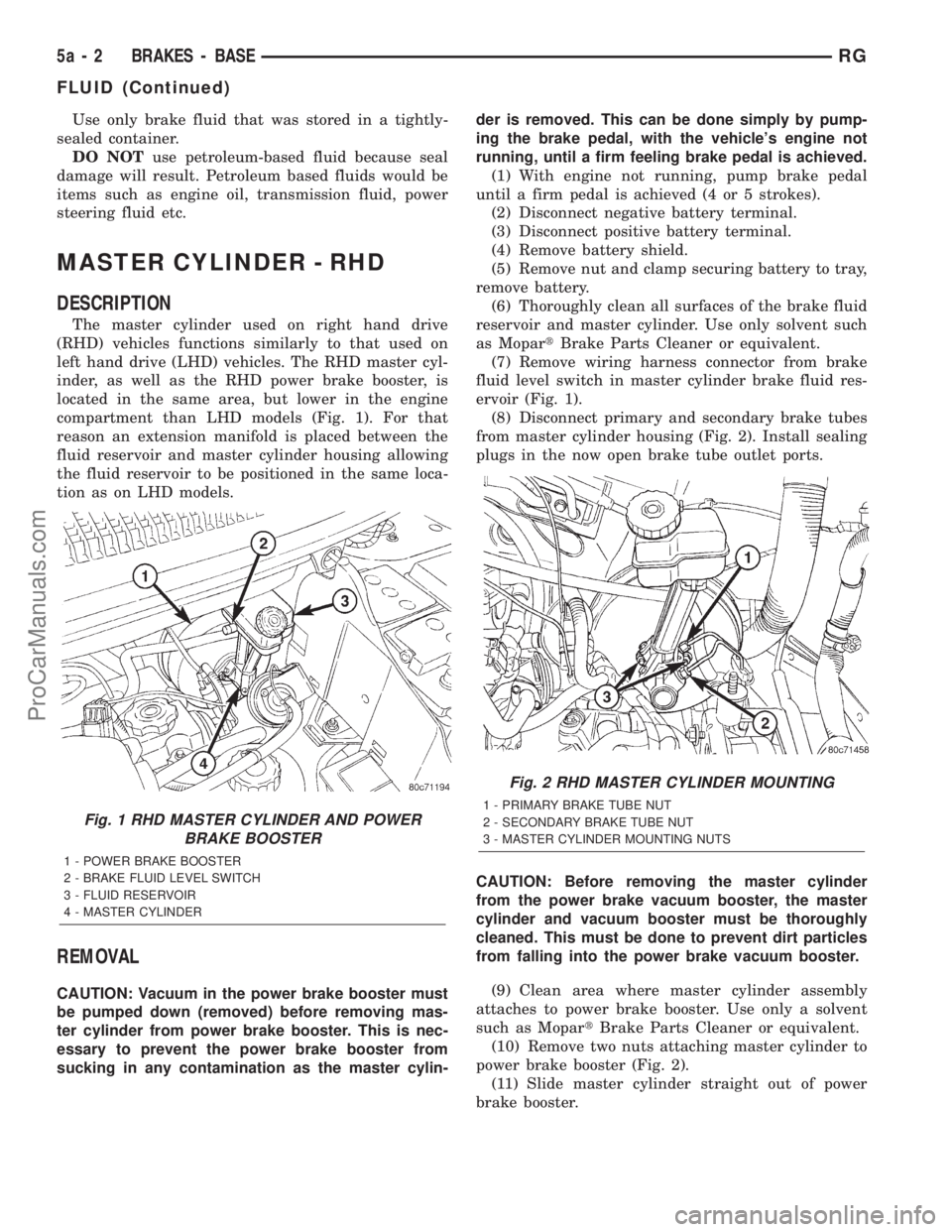
compartment than LHD models (Fig. 1). For that
reason an extension manifold is placed between the
fluid reservoir and master cylinder housing allowing
the fluid reservoir to be positioned in the same loca-
tion as on LHD models.
REMOVAL
CAUTION: Vacuum in the power brake booster must
be pumped down (removed) before removing mas-
ter cylinder from power brake booster. This is nec-
essary to prevent the power brake booster from
sucking in any contamination as the master cylin-der is removed. This can be done simply by pump-
ing the brake pedal, with the vehicle's engine not
running, until a firm feeling brake pedal is achieved.
(1) With engine not running, pump brake pedal
until a firm pedal is achieved (4 or 5 strokes).
(2) Disconnect negative battery terminal.
(3) Disconnect positive battery terminal.
(4) Remove battery shield.
(5) Remove nut and clamp securing battery to tray,
remove battery.
(6) Thoroughly clean all surfaces of the brake fluid
reservoir and master cylinder. Use only solvent such
as MopartBrake Parts Cleaner or equivalent.
(7) Remove wiring harness connector from brake
fluid level switch in master cylinder brake fluid res-
ervoir (Fig. 1).
(8) Disconnect primary and secondary brake tubes
from master cylinder housing (Fig. 2). Install sealing
plugs in the now open brake tube outlet ports.
CAUTION: Before removing the master cylinder
from the power brake vacuum booster, the master
cylinder and vacuum booster must be thoroughly
cleaned. This must be done to prevent dirt particles
from falling into the power brake vacuum booster.
(9) Clean area where master cylinder assembly
attaches to power brake booster. Use only a solvent
such as MopartBrake Parts Cleaner or equivalent.
(10) Remove two nuts attaching master cylinder to
power brake booster (Fig. 2).
(11) Slide master cylinder straight out of power
brake booster.
Fig. 1 RHD MASTER CYLINDER AND POWER
BRAKE BOOSTER
1 - POWER BRAKE BOOSTER
2 - BRAKE FLUID LEVEL SWITCH
3 - FLUID RESERVOIR
4 - MASTER CYLINDER
Fig. 2 RHD MASTER CYLINDER MOUNTING
1 - PRIMARY BRAKE TUBE NUT
2 - SECONDARY BRAKE TUBE NUT
3 - MASTER CYLINDER MOUNTING NUTS
5a - 2 BRAKES - BASERG
FLUID (Continued)
ProCarManuals.com
Page 259 of 2321
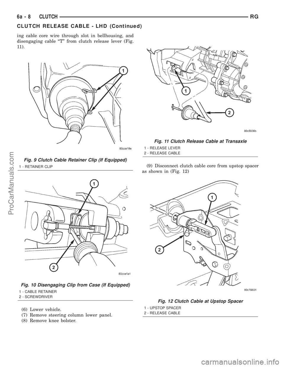
ing cable core wire through slot in bellhousing, and
disengaging cable ªTº from clutch release lever (Fig.
11).
(6) Lower vehicle.
(7) Remove steering column lower panel.
(8) Remove knee bolster.(9) Disconnect clutch cable core from upstop spacer
as shown in (Fig. 12)
Fig. 9 Clutch Cable Retainer Clip (If Equipped)
1 - RETAINER CLIP
Fig. 10 Disengaging Clip from Case (If Equipped)
1 - CABLE RETAINER
2 - SCREWDRIVER
Fig. 11 Clutch Release Cable at Transaxle
1 - RELEASE LEVER
2 - RELEASE CABLE
Fig. 12 Clutch Cable at Upstop Spacer
1 - UPSTOP SPACER
2 - RELEASE CABLE
6a - 8 CLUTCHRG
CLUTCH RELEASE CABLE - LHD (Continued)
ProCarManuals.com
Page 261 of 2321
(7) Install bellhousing cap.
(8)Diesel models:Install underbody splash
shield.(9) Lower vehicle.
(10) Verify proper clutch pedal/cable operation.
(11) Install knee bolster.
(12) Install steering column lower panel.
(13) Connect battery negative cable.
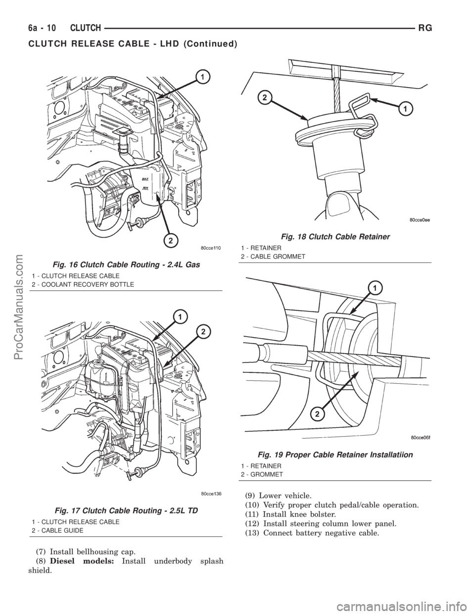
Fig. 16 Clutch Cable Routing - 2.4L Gas
1 - CLUTCH RELEASE CABLE
2 - COOLANT RECOVERY BOTTLE
Fig. 17 Clutch Cable Routing - 2.5L TD
1 - CLUTCH RELEASE CABLE
2 - CABLE GUIDE
Fig. 18 Clutch Cable Retainer
1 - RETAINER
2 - CABLE GROMMET
Fig. 19 Proper Cable Retainer Installatiion
1 - RETAINER
2 - GROMMET
6a - 10 CLUTCHRG
CLUTCH RELEASE CABLE - LHD (Continued)
ProCarManuals.com
Page 274 of 2321
ACCESSORY DRIVE
TABLE OF CONTENTS
page page
ACCESSORY DRIVE
SPECIFICATIONS.........................7
BELT TENSIONER - 2.4L
REMOVAL...............................7
INSTALLATION............................7
BELT TENSIONER - 3.3/3.8L
REMOVAL...............................8
INSTALLATION............................8
DRIVE BELTS
DESCRIPTION............................8
OPERATION.............................8
DIAGNOSIS AND TESTING..................8ACCESSORY DRIVE BELT.................8
DRIVE BELTS - 2.4L
REMOVAL...............................9
CLEANING..............................10
INSPECTION............................10
INSTALLATION...........................10
ADJUSTMENTS..........................10
DRIVE BELTS - 3.3/3.8L
REMOVAL..............................11
CLEANING..............................11
INSPECTION............................11
INSTALLATION...........................12
ACCESSORY DRIVE
SPECIFICATIONS
SPECIFICATIONS - ACCESSORY BELT TENSION
ACCESSORY DRIVE
BELTGAUGE
2.4L ENGINE
A/C Compressor/
GeneratorDynamic Tensioner
Power SteeringNew Belt: 616 N (140
lbs.)
Used Belt: 396 N (90
lbs.)
3.3/3.8L ENGINES
A/C Compressor
Dynamic Tensioner
Generator/Water
Pump/Power Steering
BELT TENSIONER - 2.4L
REMOVAL
(1) Raise vehicle on hoist.
(2) Remove the drive belt shield.(3) Remove the generator/A/C drive belt. (Refer to
7 - COOLING/ACCESSORY DRIVE/DRIVE BELTS -
REMOVAL)
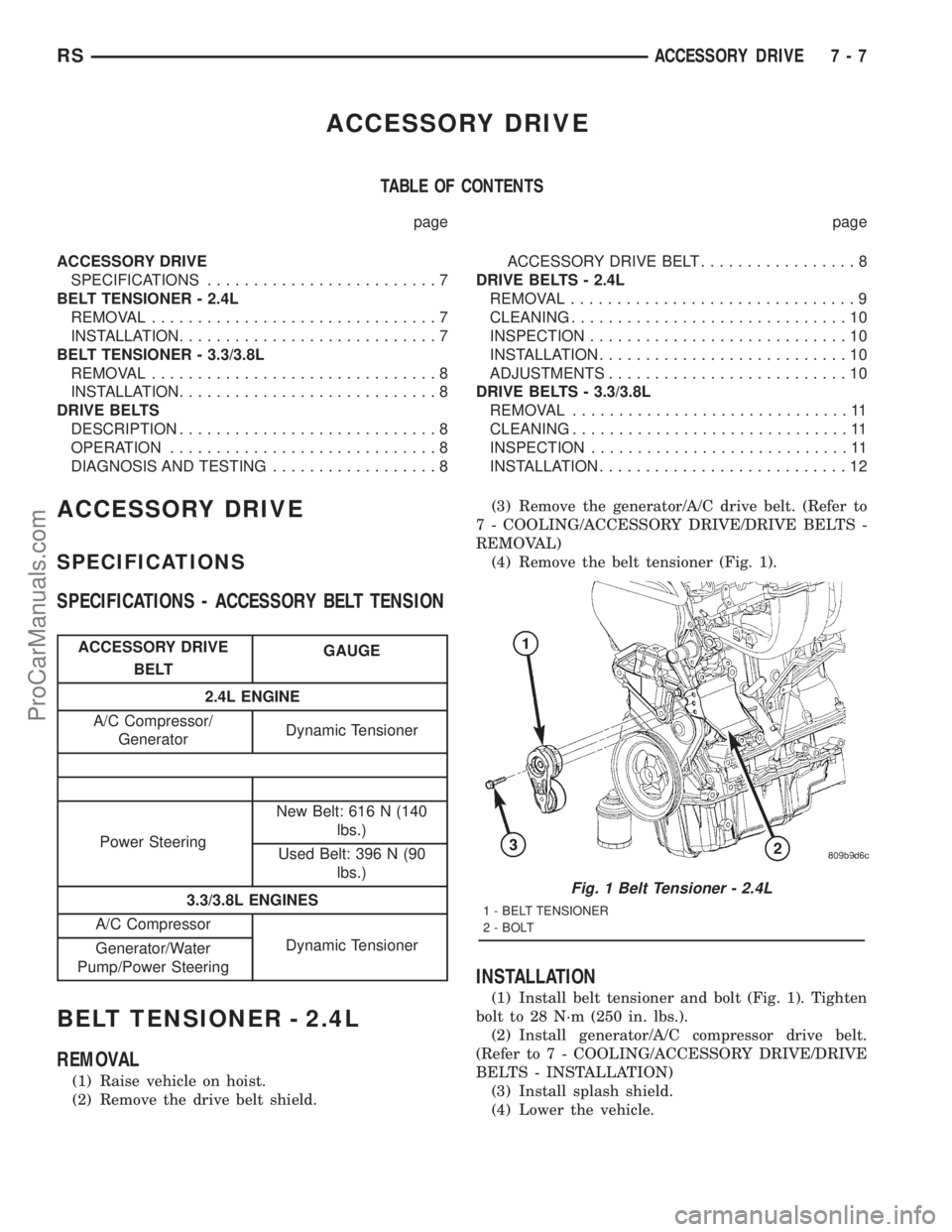
(4) Remove the belt tensioner (Fig. 1).
INSTALLATION
(1) Install belt tensioner and bolt (Fig. 1). Tighten
bolt to 28 N´m (250 in. lbs.).
(2) Install generator/A/C compressor drive belt.
(Refer to 7 - COOLING/ACCESSORY DRIVE/DRIVE
BELTS - INSTALLATION)
(3) Install splash shield.
(4) Lower the vehicle.
Fig. 1 Belt Tensioner - 2.4L
1 - BELT TENSIONER
2 - BOLT
RSACCESSORY DRIVE7-7
ProCarManuals.com