2001 DODGE TOWN AND COUNTRY brake sensor
[x] Cancel search: brake sensorPage 1090 of 2321
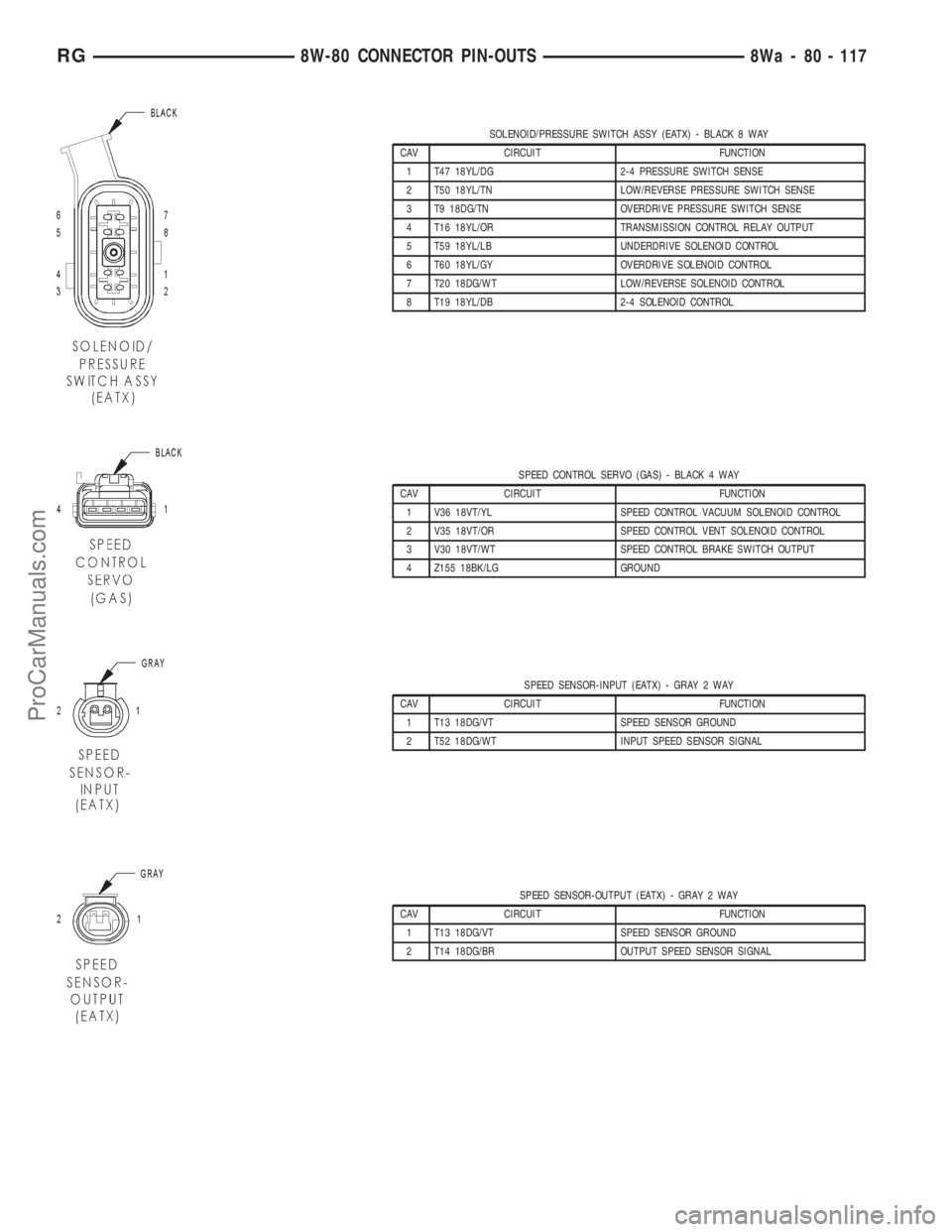
SOLENOID/PRESSURE SWITCH ASSY (EATX) - BLACK 8 WAY
CAV CIRCUIT FUNCTION
1 T47 18YL/DG 2-4 PRESSURE SWITCH SENSE
2 T50 18YL/TN LOW/REVERSE PRESSURE SWITCH SENSE
3 T9 18DG/TN OVERDRIVE PRESSURE SWITCH SENSE
4 T16 18YL/OR TRANSMISSION CONTROL RELAY OUTPUT
5 T59 18YL/LB UNDERDRIVE SOLENOID CONTROL
6 T60 18YL/GY OVERDRIVE SOLENOID CONTROL
7 T20 18DG/WT LOW/REVERSE SOLENOID CONTROL
8 T19 18YL/DB 2-4 SOLENOID CONTROL
SPEED CONTROL SERVO (GAS) - BLACK 4 WAY
CAV CIRCUIT FUNCTION
1 V36 18VT/YL SPEED CONTROL VACUUM SOLENOID CONTROL
2 V35 18VT/OR SPEED CONTROL VENT SOLENOID CONTROL
3 V30 18VT/WT SPEED CONTROL BRAKE SWITCH OUTPUT
4 Z155 18BK/LG GROUND
SPEED SENSOR-INPUT (EATX) - GRAY 2 WAY
CAV CIRCUIT FUNCTION
1 T13 18DG/VT SPEED SENSOR GROUND
2 T52 18DG/WT INPUT SPEED SENSOR SIGNAL
SPEED SENSOR-OUTPUT (EATX) - GRAY 2 WAY
CAV CIRCUIT FUNCTION
1 T13 18DG/VT SPEED SENSOR GROUND
2 T14 18DG/BR OUTPUT SPEED SENSOR SIGNAL
RG8W-80 CONNECTOR PIN-OUTS8Wa - 80 - 117
ProCarManuals.com
Page 1097 of 2321
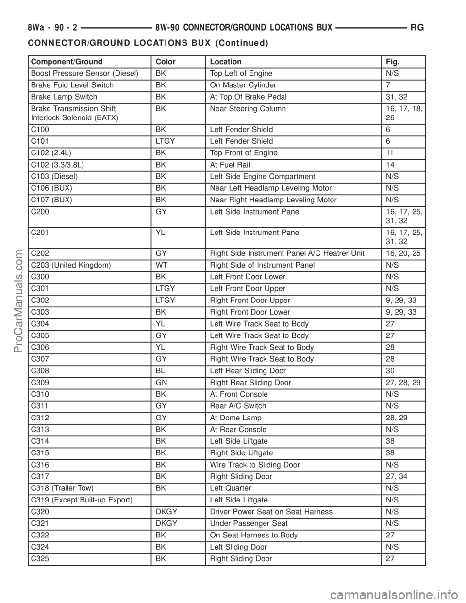
Component/Ground Color Location Fig.
Boost Pressure Sensor (Diesel) BK Top Left of Engine N/S
Brake Fuid Level Switch BK On Master Cylinder 7
Brake Lamp Switch BK At Top Of Brake Pedal 31, 32
Brake Transmission Shift
Interlock Solenoid (EATX)BK Near Steering Column 16, 17, 18,
26
C100 BK Left Fender Shield 6
C101 LTGY Left Fender Shield 6
C102 (2.4L) BK Top Front of Engine 11
C102 (3.3/3.8L) BK At Fuel Rail 14
C103 (Diesel) BK Left Side Engine Compartment N/S
C106 (BUX) BK Near Left Headlamp Leveling Motor N/S
C107 (BUX) BK Near Right Headlamp Leveling Motor N/S
C200 GY Left Side Instrument Panel 16, 17, 25,
31, 32
C201 YL Left Side Instrument Panel 16, 17, 25,
31, 32
C202 GY Right Side Instrument Panel A/C Heatrer Unit 16, 20, 25
C203 (United Kingdom) WT Right Side of Instrument Panel N/S
C300 BK Left Front Door Lower N/S
C301 LTGY Left Front Door Upper N/S
C302 LTGY Right Front Door Upper 9, 29, 33
C303 BK Right Front Door Lower 9, 29, 33
C304 YL Left Wire Track Seat to Body 27
C305 GY Left Wire Track Seat to Body 27
C306 YL Right Wire Track Seat to Body 28
C307 GY Right Wire Track Seat to Body 28
C308 BL Left Rear Sliding Door 30
C309 GN Right Rear Sliding Door 27, 28, 29
C310 BK At Front Console N/S
C311 GY Rear A/C Switch N/S
C312 GY At Dome Lamp 28, 29
C313 BK At Rear Console N/S
C314 BK Left Side Liftgate 38
C315 BK Right Side Liftgate 38
C316 BK Wire Track to Sliding Door N/S
C317 BK Right Sliding Door 27, 34
C318 (Trailer Tow) BK Left Quarter N/S
C319 (Except Built-up Export) Left Side Liftgate N/S
C320 DKGY Driver Power Seat on Seat Harness N/S
C321 DKGY Under Passenger Seat N/S
C322 BK On Seat Harness to Body 27
C324 BK Left Sliding Door N/S
C325 BK Right Sliding Door 27
8Wa - 90 - 2 8W-90 CONNECTOR/GROUND LOCATIONS BUXRG
CONNECTOR/GROUND LOCATIONS BUX (Continued)
ProCarManuals.com
Page 1098 of 2321
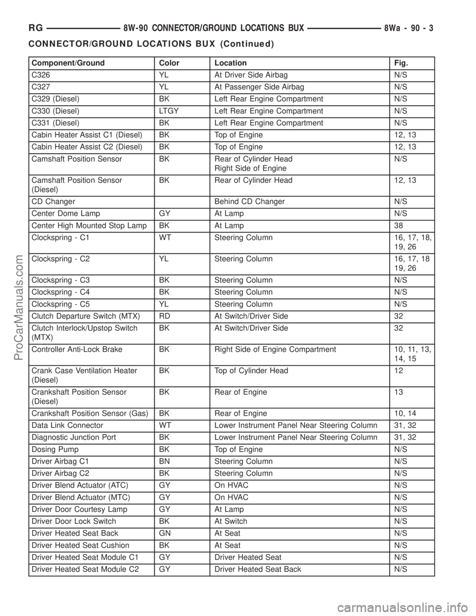
Component/Ground Color Location Fig.
C326 YL At Driver Side Airbag N/S
C327 YL At Passenger Side Airbag N/S
C329 (Diesel) BK Left Rear Engine Compartment N/S
C330 (Diesel) LTGY Left Rear Engine Compartment N/S
C331 (Diesel) BK Left Rear Engine Compartment N/S
Cabin Heater Assist C1 (Diesel) BK Top of Engine 12, 13
Cabin Heater Assist C2 (Diesel) BK Top of Engine 12, 13
Camshaft Position Sensor BK Rear of Cylinder Head
Right Side of EngineN/S
Camshaft Position Sensor
(Diesel)BK Rear of Cylinder Head 12, 13
CD Changer Behind CD Changer N/S
Center Dome Lamp GY At Lamp N/S
Center High Mounted Stop Lamp BK At Lamp 38
Clockspring - C1 WT Steering Column 16, 17, 18,
19, 26
Clockspring - C2 YL Steering Column 16, 17, 18
19, 26
Clockspring - C3 BK Steering Column N/S
Clockspring - C4 BK Steering Column N/S
Clockspring - C5 YL Steering Column N/S
Clutch Departure Switch (MTX) RD At Switch/Driver Side 32
Clutch Interlock/Upstop Switch
(MTX)BK At Switch/Driver Side 32
Controller Anti-Lock Brake BK Right Side of Engine Compartment 10, 11, 13,
14, 15
Crank Case Ventilation Heater
(Diesel)BK Top of Cylinder Head 12
Crankshaft Position Sensor
(Diesel)BK Rear of Engine 13
Crankshaft Position Sensor (Gas) BK Rear of Engine 10, 14
Data Link Connector WT Lower Instrument Panel Near Steering Column 31, 32
Diagnostic Junction Port BK Lower Instrument Panel Near Steering Column 31, 32
Dosing Pump BK Top of Engine N/S
Driver Airbag C1 BN Steering Column N/S
Driver Airbag C2 BK Steering Column N/S
Driver Blend Actuator (ATC) GY On HVAC N/S
Driver Blend Actuator (MTC) GY On HVAC N/S
Driver Door Courtesy Lamp GY At Lamp N/S
Driver Door Lock Switch BK At Switch N/S
Driver Heated Seat Back GN At Seat N/S
Driver Heated Seat Cushion BK At Seat N/S
Driver Heated Seat Module C1 GY Driver Heated Seat N/S
Driver Heated Seat Module C2 GY Driver Heated Seat Back N/S
RG8W-90 CONNECTOR/GROUND LOCATIONS BUX8Wa-90-3
CONNECTOR/GROUND LOCATIONS BUX (Continued)
ProCarManuals.com
Page 1106 of 2321
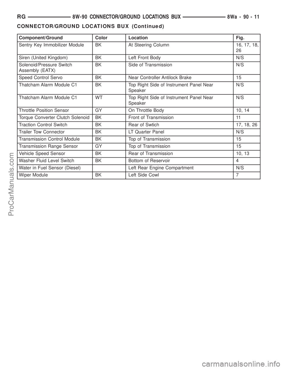
Component/Ground Color Location Fig.
Sentry Key Immobilizer Module BK At Steering Column 16, 17, 18,
26
Siren (United Kingdom) BK Left Front Body N/S
Solenoid/Pressure Switch
Assembly (EATX)BK Side of Transmission N/S
Speed Control Servo BK Near Controller Antilock Brake 15
Thatcham Alarm Module C1 BK Top Right Side of Instrument Panel Near
SpeakerN/S
Thatcham Alarm Module C1 WT Top Right Side of Instrument Panel Near
SpeakerN/S
Throttle Position Sensor GY On Throttle Body 10, 14
Torque Converter Clutch Solenoid BK Front of Transmission 11
Traction Control Switch BK Rear of Swtich 17, 18, 26
Trailer Tow Connector BK LT Quarter Panel N/S
Transmission Control Module BK Top of Transmission 15
Transmission Range Sensor GY Top of Transmission 15
Vehicle Speed Sensor BK Rear of Transmission 10, 13
Washer Fluid Level Switch BK Bottom of Reservoir 4
Water in Fuel Sensor (Diesel) Left Rear Engine Compartment N/S
Wiper Module BK Left Side Cowl 7
RG8W-90 CONNECTOR/GROUND LOCATIONS BUX8Wa-90-11
CONNECTOR/GROUND LOCATIONS BUX (Continued)
ProCarManuals.com
Page 1214 of 2321
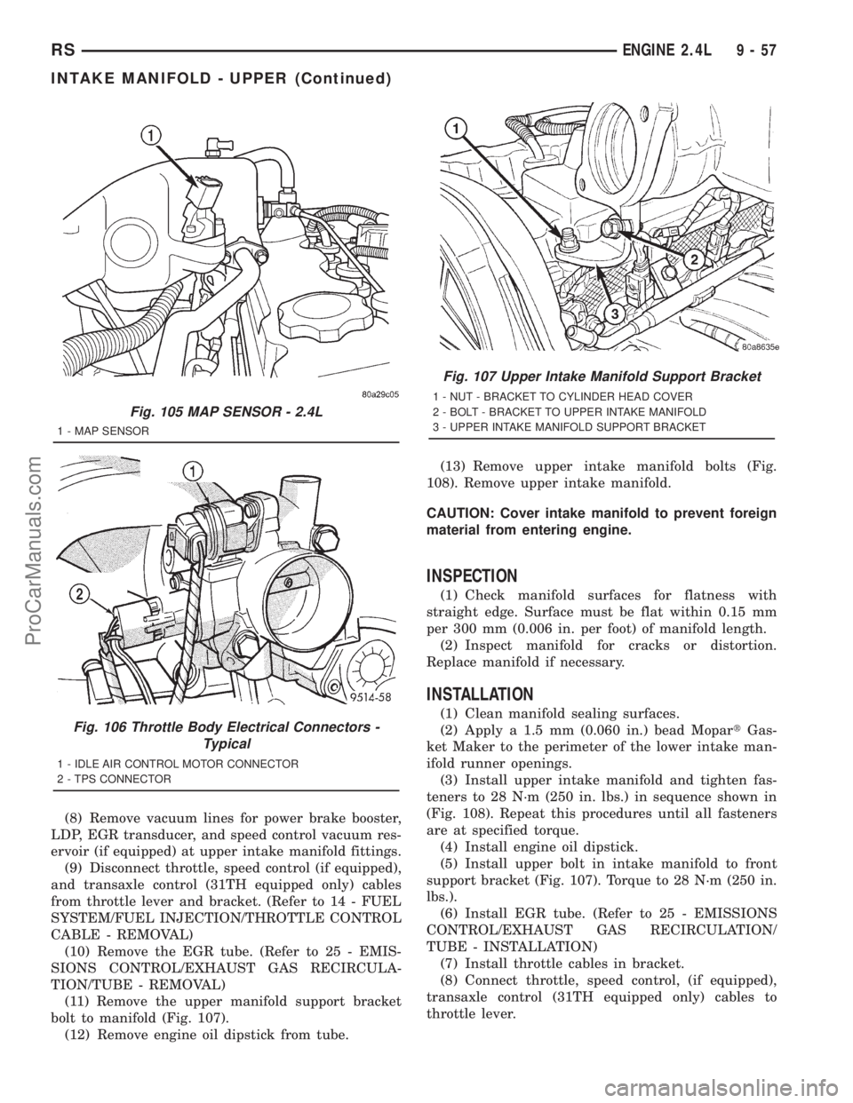
(8) Remove vacuum lines for power brake booster,
LDP, EGR transducer, and speed control vacuum res-
ervoir (if equipped) at upper intake manifold fittings.
(9) Disconnect throttle, speed control (if equipped),
and transaxle control (31TH equipped only) cables
from throttle lever and bracket. (Refer to 14 - FUEL
SYSTEM/FUEL INJECTION/THROTTLE CONTROL
CABLE - REMOVAL)
(10) Remove the EGR tube. (Refer to 25 - EMIS-
SIONS CONTROL/EXHAUST GAS RECIRCULA-
TION/TUBE - REMOVAL)
(11) Remove the upper manifold support bracket
bolt to manifold (Fig. 107).
(12) Remove engine oil dipstick from tube.(13) Remove upper intake manifold bolts (Fig.
108). Remove upper intake manifold.
CAUTION: Cover intake manifold to prevent foreign
material from entering engine.
INSPECTION
(1) Check manifold surfaces for flatness with
straight edge. Surface must be flat within 0.15 mm
per 300 mm (0.006 in. per foot) of manifold length.
(2) Inspect manifold for cracks or distortion.
Replace manifold if necessary.
INSTALLATION
(1) Clean manifold sealing surfaces.
(2) Apply a 1.5 mm (0.060 in.) bead MopartGas-
ket Maker to the perimeter of the lower intake man-
ifold runner openings.
(3) Install upper intake manifold and tighten fas-
teners to 28 N´m (250 in. lbs.) in sequence shown in
(Fig. 108). Repeat this procedures until all fasteners
are at specified torque.
(4) Install engine oil dipstick.
(5) Install upper bolt in intake manifold to front
support bracket (Fig. 107). Torque to 28 N´m (250 in.
lbs.).
(6) Install EGR tube. (Refer to 25 - EMISSIONS
CONTROL/EXHAUST GAS RECIRCULATION/
TUBE - INSTALLATION)
(7) Install throttle cables in bracket.
(8) Connect throttle, speed control, (if equipped),
transaxle control (31TH equipped only) cables to
throttle lever.
Fig. 105 MAP SENSOR - 2.4L
1 - MAP SENSOR
Fig. 106 Throttle Body Electrical Connectors -
Typical
1 - IDLE AIR CONTROL MOTOR CONNECTOR
2 - TPS CONNECTOR
Fig. 107 Upper Intake Manifold Support Bracket
1 - NUT - BRACKET TO CYLINDER HEAD COVER
2 - BOLT - BRACKET TO UPPER INTAKE MANIFOLD
3 - UPPER INTAKE MANIFOLD SUPPORT BRACKET
RSENGINE 2.4L9-57
INTAKE MANIFOLD - UPPER (Continued)
ProCarManuals.com
Page 1215 of 2321
(9) Connect vacuum lines for power brake booster,
LDP, EGR transducer, and speed control vacuum res-
ervoir (if equipped) at upper intake manifold fittings.
(10) Connect vacuum lines for purge solenoid and
PCV valve.
(11) Connect electrical connectors for MAP sensor,
throttle position sensor (TPS), and idle air control
(IAC) motor.
(12) Install air cleaner upper housing and air
intake tube to throttle body.
(13) Connect inlet air temperature sensor connec-
tor (Fig. 104).
(14) Connect negative cable to battery.
INTAKE MANIFOLD - LOWER
REMOVAL
(1) Perform fuel system pressure release proce-
durebefore attempting any repairs.(Refer to 14 -
FUEL SYSTEM/FUEL DELIVERY - STANDARD
PROCEDURE)
(2) Remove upper intake manifold. (Refer to 9 -
ENGINE/MANIFOLDS/INTAKE MANIFOLD -
REMOVAL)
CAUTION: Cover intake manifold openings to pre-
vent foreign material from entering engine.
(3) Disconnect fuel line. (Refer to 14 - FUEL SYS-
TEM/FUEL DELIVERY/QUICK CONNECT FIT-
TING - STANDARD PROCEDURE)
(4) Drain the cooling system. (Refer to 7 - COOL-
ING - STANDARD PROCEDURE)
(5) Remove heater supply and radiator upper
hoses at intake manifold.
(6) Disconnect coolant temperature sensor/fuel
injector wire harness connector.
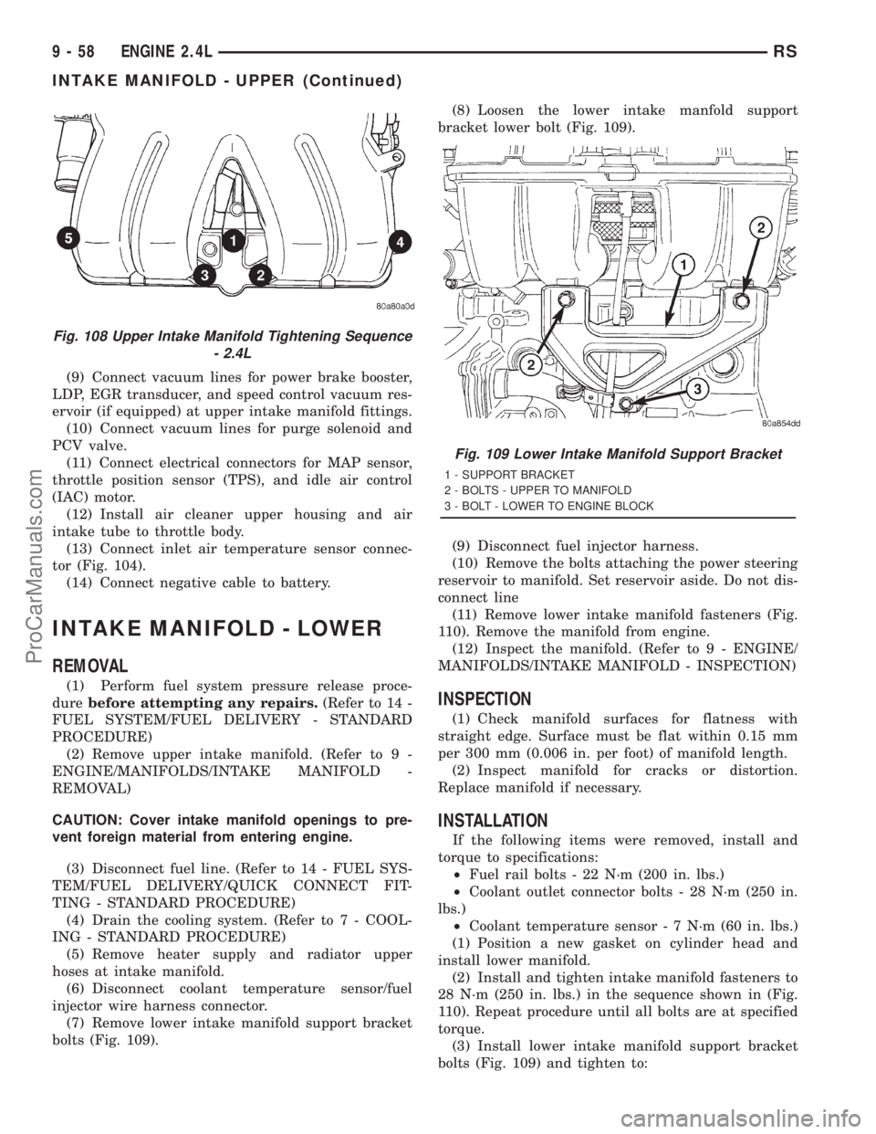
(7) Remove lower intake manifold support bracket
bolts (Fig. 109).(8) Loosen the lower intake manfold support
bracket lower bolt (Fig. 109).
(9) Disconnect fuel injector harness.
(10) Remove the bolts attaching the power steering
reservoir to manifold. Set reservoir aside. Do not dis-
connect line
(11) Remove lower intake manifold fasteners (Fig.
110). Remove the manifold from engine.
(12) Inspect the manifold. (Refer to 9 - ENGINE/
MANIFOLDS/INTAKE MANIFOLD - INSPECTION)
INSPECTION
(1) Check manifold surfaces for flatness with
straight edge. Surface must be flat within 0.15 mm
per 300 mm (0.006 in. per foot) of manifold length.
(2) Inspect manifold for cracks or distortion.
Replace manifold if necessary.
INSTALLATION
If the following items were removed, install and
torque to specifications:
²Fuel rail bolts - 22 N´m (200 in. lbs.)
²Coolant outlet connector bolts - 28 N´m (250 in.
lbs.)
²Coolant temperature sensor - 7 N´m (60 in. lbs.)
(1) Position a new gasket on cylinder head and
install lower manifold.
(2) Install and tighten intake manifold fasteners to
28 N´m (250 in. lbs.) in the sequence shown in (Fig.
110). Repeat procedure until all bolts are at specified
torque.
(3) Install lower intake manifold support bracket
bolts (Fig. 109) and tighten to:
Fig. 108 Upper Intake Manifold Tightening Sequence
- 2.4L
Fig. 109 Lower Intake Manifold Support Bracket
1 - SUPPORT BRACKET
2 - BOLTS - UPPER TO MANIFOLD
3 - BOLT - LOWER TO ENGINE BLOCK
9 - 58 ENGINE 2.4LRS
INTAKE MANIFOLD - UPPER (Continued)
ProCarManuals.com
Page 1239 of 2321
REMOVAL - ENGINE ASSEMBLY
(1) Perform fuel pressure release procedure. (Refer
to 14 - FUEL SYSTEM/FUEL DELIVERY - STAN-
DARD PROCEDURE)
(2) Disconnect the battery.
(3) Remove air cleaner and hoses.
(4) Disconnect the fuel line from fuel rail. (Refer to
14 - FUEL SYSTEM/FUEL DELIVERY/QUICK
CONNECT FITTING - STANDARD PROCEDURE)
(5) Remove the wiper module. (Refer to 8 - ELEC-
TRICAL/WIPERS/WASHERS/WIPER MODULE -
REMOVAL)
(6) Block off heater hoses to the rear heater sys-
tem, if equipped, using pinch-off pliers.
(7) Drain the cooling system. (Refer to 7 - COOL-
ING - STANDARD PROCEDURE)
(8) Disconnect the heater hoses.
(9) Remove the radiator upper support crossmem-
ber. (Refer to 23 - BODY/EXTERIOR/GRILLE OPEN-
ING REINFORCEMENT - REMOVAL)
(10) Remove the radiator fans. (Refer to 7 - COOL-
ING/ENGINE/RADIATOR FAN - REMOVAL)
(11) Disconnect the throttle cables from the throt-
tle body.
(12) Disconnect the MAP, IAC, and TPS electrical
connectors.
(13) Disconnect the EGR transducer electrical con-
nector.
(14) Disconnect the vacuum hoses from throttle
body.
(15) Disconnect the brake booster and speed con-
trol vacuum hoses.(16) Disengage wire harness clip from the right
side engine mount.
(17) Remove the power steering reservoir from
mounting position and set aside. Do not disconnect
hose.
(18) Disconnect ground strap from rear of cylinder
head.
(19) Disconnect engine coolant temperature (ECT)
sensor and ignition coil electrical connectors.
(20) Disconnect the fuel injector electrical harness
connector and disengage clip from support bracket.
(21) Disconnect crank sensor connector.
(22) Disconnect camshaft sensor connector.
(23) Evacuate air conditioning system.
(24) Disconnect A/C compressor electrical connec-
tor.
(25) Disconnect the A/C lines from compressor.
Cover and seal all openings of hoses and compressor.
(26) Remove the radiator upper hose.
(27) Disengage electrical harness clip at transaxle
dipstick tube.
(28) Remove transaxle dipstick tube. Seal opening
using a suitable plug.
(29) Disconnect cooler hoses from transaxle.
(30) Disconnect transaxle shift linkage and electri-
cal connectors.
(31) Raise vehicle on hoist and drain the engine
oil.
(32) Remove the axle shafts. (Refer to 3 - DIFFER-
ENTIAL & DRIVELINE/HALF SHAFT - REMOVAL)
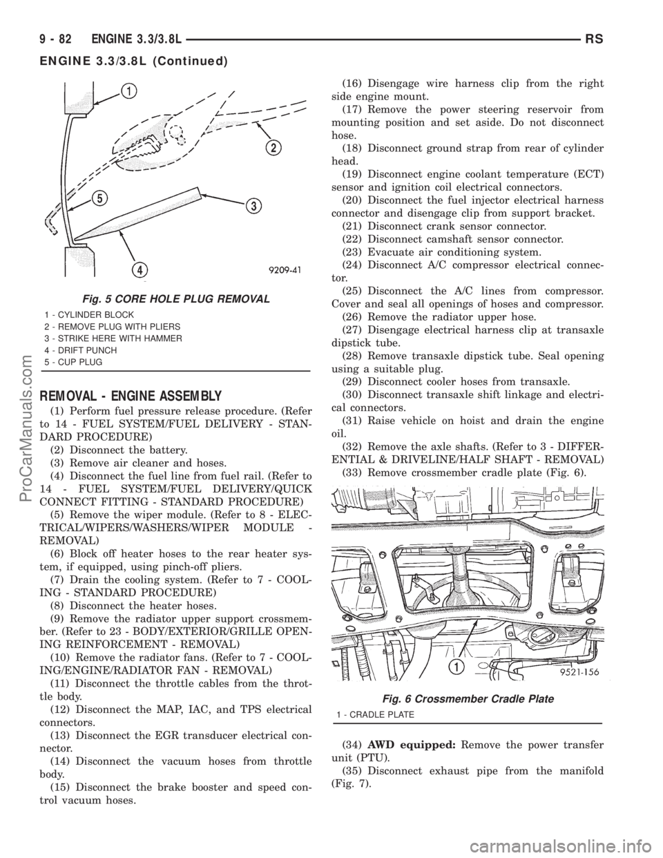
(33) Remove crossmember cradle plate (Fig. 6).
(34)AWD equipped:Remove the power transfer
unit (PTU).
(35) Disconnect exhaust pipe from the manifold
(Fig. 7).
Fig. 5 CORE HOLE PLUG REMOVAL
1 - CYLINDER BLOCK
2 - REMOVE PLUG WITH PLIERS
3 - STRIKE HERE WITH HAMMER
4 - DRIFT PUNCH
5 - CUP PLUG
Fig. 6 Crossmember Cradle Plate
1 - CRADLE PLATE
9 - 82 ENGINE 3.3/3.8LRS
ENGINE 3.3/3.8L (Continued)
ProCarManuals.com
Page 1242 of 2321
(4) Slowly raise vehicle enough to remove the
engine dolly and cradle Special Tools 6135, 6710,
6848 and 6909 (Fig. 10).
(5) Remove Special Tools 6912 and 8444.
(6) Lower the vehicle.
(7) Install power steering pump and pressure line
support.(8) Install the generator and wiring harness.
(Refer to 8 - ELECTRICAL/CHARGING/GENERA-
TOR - INSTALLATION)
(9) Raise vehicle.
(10) Attach wiring harness support clip to the dip-
stick tube.
(11) Connect oil pressure switch electrical connec-
tor.
(12) Install the A/C compressor.
(13) Install the water pump pulley.
(14) Connect the radiator lower hose.
(15) Install the accessory drive belt and splash
shield. (Refer to 7 - COOLING/ACCESSORY DRIVE/
DRIVE BELTS - INSTALLATION)
(16) Connect the engine block heater electrical con-
nector, if equipped.
(17) Connect the knock sensor electrical connector
(3.8L only).
(18) Install the torque converter to flex plate bolts.
(19) Install the transaxle case cover (Fig. 8).
(20) Install the powertrain struts (Fig. 8).
(21) Install the engine rear mount bracket.
(22) Install the engine front mount and bracket
assembly.
(23)AWD equipped;Install the power transfer
unit (PTU).
(24) Install the axle shafts. (Refer to 3 - DIFFER-
ENTIAL & DRIVELINE/HALF SHAFT - INSTALLA-
TION)
(25) Connect exhaust pipe to manifold (Fig. 7).
(26) Install crossmember cradle plate (Fig. 6).
(27) Lower vehicle.
(28) Connect transaxle shift linkage.
(29) Connect transaxle electrical connectors.
(30) Connect transaxle cooler hoses.
(31) Install transaxle dipstick tube and attach
electrical harness clip.
(32) Connect the radiator upper hose.
(33) Connect the A/C lines to compressor.
(34) Connect the A/C compressor electrical connec-
tor.
(35) Evacuate and recharge A/C system.
(36) Connect crankshaft and camshaft position
sensors.
(37) Connect the fuel injector electrical harness
connector and engage clip to support bracket.
(38) Connect engine coolant temperature (ECT)
sensor and ignition coil electrical connectors.
(39) Connect the ground strap to rear of cylinder
head.
(40) Install power steering reservoir.
(41) Engage wire harness clip to engine right side
mount.
(42) Connect the brake booster and speed control
vacuum hoses.
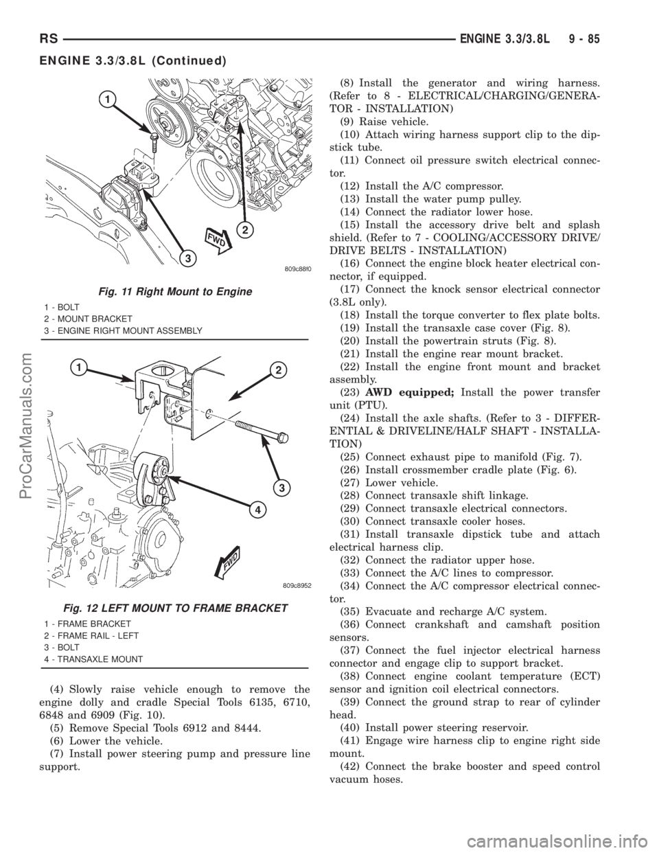
Fig. 11 Right Mount to Engine
1 - BOLT
2 - MOUNT BRACKET
3 - ENGINE RIGHT MOUNT ASSEMBLY
Fig. 12 LEFT MOUNT TO FRAME BRACKET
1 - FRAME BRACKET
2 - FRAME RAIL - LEFT
3 - BOLT
4 - TRANSAXLE MOUNT
RSENGINE 3.3/3.8L9-85
ENGINE 3.3/3.8L (Continued)
ProCarManuals.com