2001 DODGE TOWN AND COUNTRY boot
[x] Cancel search: bootPage 209 of 2321
WHEEL CYLINDERS
REMOVAL
(1) Using a brake pedal depressor, move and
secure brake pedal to a position past its first 1 inch
of travel. This will prevent brake fluid from draining
out of master cylinder when brake tube is remove
from wheel cylinder.
(2) Raise vehicle. (Refer to LUBRICATION &
MAINTENANCE/HOISTING - STANDARD PROCE-
DURE).
(3) Remove wheel and tire assembly.
(4) Disconnect brake tube from rear of wheel cylin-
der. Cap open ends
(5) Remove brake drum.
(6) Remove brake shoes from brake support plate
(Discard if contaminated).(Refer to 5 - BRAKES/HY-
DRAULIC/MECHANICAL/BRAKE PADS/SHOES -
REMOVAL)
(7) Remove the 2 bolts attaching the wheel cylin-
der to the brake support plate.
(8) Remove the wheel cylinder from the brake sup-
port plate.
INSPECTION
With brake drums removed, inspect the wheel cyl-
inder boots for evidence of a brake fluid leak. Visu-
ally check the boots for cuts, tears, or heat cracks. If
any of these conditions exist, the wheel cylinders
should be completely cleaned, inspected and new
parts installed.
If a wheel cylinder is leaking and the brake lining
material is saturated with brake fluid, the brake
shoes must be replaced.
INSTALLATION
(1) Apply sealant such as Mopar Gasket-In-A-Tube
or equivalent around the wheel cylinder opening in
the brake support plate.
(2) Install wheel cylinder onto brake support.
Install and tighten the wheel cylinder to brake sup-
port plate attaching bolts to 8 N´m (75 in. lbs.)
torque.
(3) Install brake tube into wheel cylinder. Tighten
tube nut to a torque of 17 N´m (145 in. lbs.) torque.
(4) Install the rear brake shoes on the brake sup-
port plate. (Refer to 5 - BRAKES/HYDRAULIC/ME-
CHANICAL/BRAKE PADS/SHOES -
INSTALLATION).
(5) Install brake drum.
(6) Install wheel and tire. Install and tighten
wheel lug nuts to 135 N´m (100 ft. lbs.).
(7) Adjust drum brake shoes. (Refer to 5 -
BRAKES/HYDRAULIC/MECHANICAL/BRAKE
PADS/SHOES - ADJUSTMENTS)
(8) Remove brake pedal depressor tool.(9) Bleed the brake system as necessary. (Refer to
5 - BRAKES - BASE - STANDARD PROCEDURE).
(10) Lower vehicle.
PARKING BRAKE
DESCRIPTION
The parking brake system is operated by a foot
operated parking brake lever. The parking brake
lever is mounted on the body of the vehicle to the left
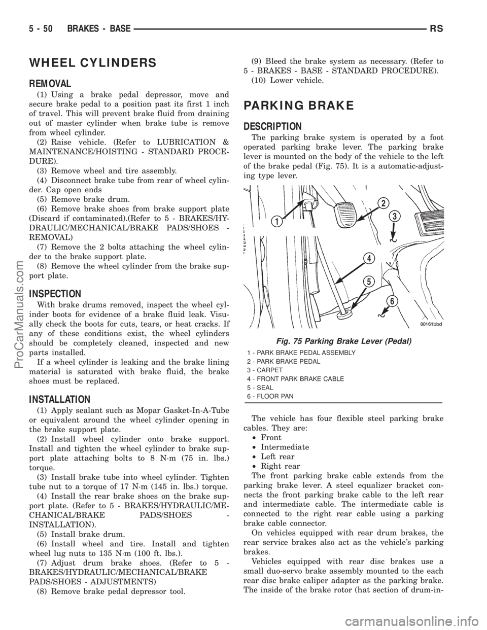
of the brake pedal (Fig. 75). It is a automatic-adjust-
ing type lever.
The vehicle has four flexible steel parking brake
cables. They are:
²Front
²Intermediate
²Left rear
²Right rear
The front parking brake cable extends from the
parking brake lever. A steel equalizer bracket con-
nects the front parking brake cable to the left rear
and intermediate cable. The intermediate cable is
connected to the right rear cable using a parking
brake cable connector.
On vehicles equipped with rear drum brakes, the
rear service brakes also act as the vehicle's parking
brakes.
Vehicles equipped with rear disc brakes use a
small duo-servo brake assembly mounted to the each
rear disc brake caliper adapter as the parking brake.
The inside of the brake rotor (hat section of drum-in-
Fig. 75 Parking Brake Lever (Pedal)
1 - PARK BRAKE PEDAL ASSEMBLY
2 - PARK BRAKE PEDAL
3 - CARPET
4 - FRONT PARK BRAKE CABLE
5 - SEAL
6 - FLOOR PAN
5 - 50 BRAKES - BASERS
ProCarManuals.com
Page 458 of 2321

CAUTION: Cleaning of the platinum plug may dam-
age the platinum tip.
REMOVAL
When replacing the spark plugs and spark plug
cables, route the cables correctly and secure them in
the appropriate retainers. Failure to route the cables
properly can cause the radio to reproduce ignition
noise, cross ignition of the spark plugs orshort cir-
cuit the cables to ground.
Always remove cables by grasping at the boot,
rotating the boot 1/2 turn, and pulling straight back
in a steady motion.
(1) Prior to removing the spark plug, spray com-
pressed air around the spark plug hole and the area
around the spark plug.
(2) Remove the spark plug using a quality socket
with a foam insert.
(3) Inspect the spark plug condition.
INSTALLATION
When replacing the spark plugs and spark plug
cables, route the cables correctly and secure them in
the appropriate retainers. Failure to route the cables
properly can cause the radio to reproduce ignition
noise, cross ignition of the spark plugs orshort cir-
cuit the cables to ground.(1) To avoid cross threading, start the spark plug
into the cylinder head by hand.
(2) Tighten spark plugs to 17.5 N´m (13 ft. lbs.)
torque.
(3) Install spark plug cables over spark plugs. A
click will be heard and felt when the cable properly
attaches to the spark plug.
SPARK PLUG CABLE
DESCRIPTION
Spark Plug cables are sometimes referred to as
secondary ignition wires. The wires transfer electri-
cal current from the ignition coil pack to individual
spark plugs at each cylinder. The resistive spark plug
cables are of nonmetallic construction. The cables
provide suppression of radio frequency emissions
from the ignition system.
Check the spark plug cable connections for good
contact at the coil, and spark plugs. Terminals should
be fully seated. The insulators should be in good con-
dition and should fit tightly on the coil, and spark
plugs. Spark plug cables with insulators that are
cracked or torn must be replaced.
Clean Spark Plug cables with a cloth moistened
with a non-flammable solvent. Wipe the cables dry.
Check for brittle or cracked insulation. The spark
plug cables and spark plug boots are made from high
temperature silicone materials. All spark plug cable
leads are properly identified with cylinder numbers.
The inside of most the spark plug boot is coated with
a special high temperature silicone grease for greater
sealing and to minimize boot bonding to the spark
plug insulator.
REMOVAL
Failure to route the cables properly could cause the
radio to reproduce ignition noise, cross ignition of the
spark plugs or short circuit the cables to ground.
Remove spark plug cable from coil first.
Always remove the spark plug cable by grasping
the top of the spark plug insulator, turning the boot
1/2 turn and pulling straight up in a steady motion.
INSTALLATION
Failure to route the cables properly could cause the
radio to reproduce ignition noise, cross ignition of the
spark plugs or short circuit the cables to ground.
Install spark plug insulators over spark plugs.
Ensure the top of the spark plug insulator covers the
upper end of the spark plug tube.Then connect the
other end to coil pack.
Fig. 15 Setting Spark Plug Electrode Gap
1 - TAPER GAUGE
RSIGNITION CONTROL8I-9
SPARK PLUG (Continued)
ProCarManuals.com
Page 496 of 2321
FRONT POSITION LAMP
REMOVAL
(1) Disconnect and isolate the battery negative
cable.
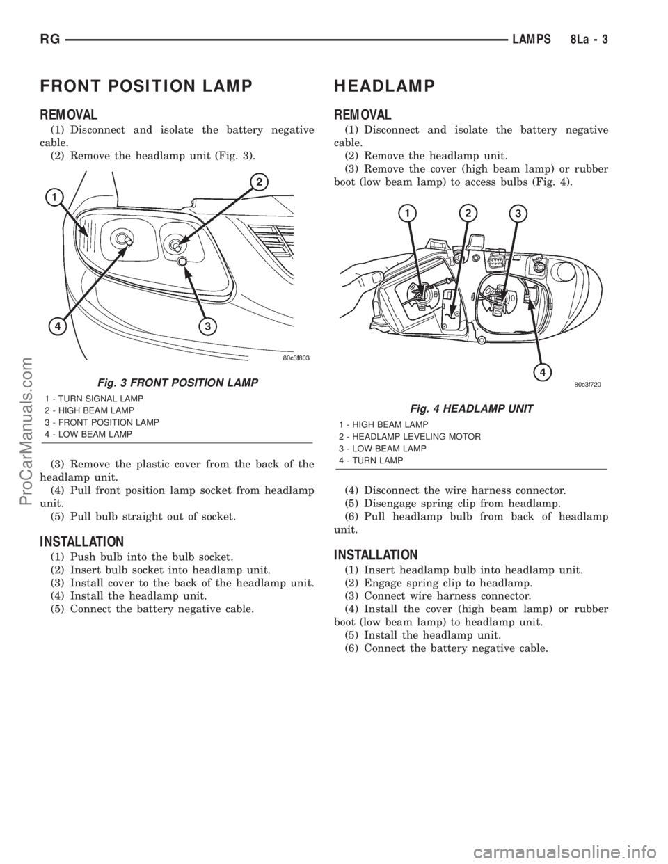
(2) Remove the headlamp unit (Fig. 3).
(3) Remove the plastic cover from the back of the
headlamp unit.
(4) Pull front position lamp socket from headlamp
unit.
(5) Pull bulb straight out of socket.
INSTALLATION
(1) Push bulb into the bulb socket.
(2) Insert bulb socket into headlamp unit.
(3) Install cover to the back of the headlamp unit.
(4) Install the headlamp unit.
(5) Connect the battery negative cable.
HEADLAMP
REMOVAL
(1) Disconnect and isolate the battery negative
cable.
(2) Remove the headlamp unit.
(3) Remove the cover (high beam lamp) or rubber
boot (low beam lamp) to access bulbs (Fig. 4).
(4) Disconnect the wire harness connector.
(5) Disengage spring clip from headlamp.
(6) Pull headlamp bulb from back of headlamp
unit.
INSTALLATION
(1) Insert headlamp bulb into headlamp unit.
(2) Engage spring clip to headlamp.
(3) Connect wire harness connector.
(4) Install the cover (high beam lamp) or rubber
boot (low beam lamp) to headlamp unit.
(5) Install the headlamp unit.
(6) Connect the battery negative cable.
Fig. 3 FRONT POSITION LAMP
1 - TURN SIGNAL LAMP
2 - HIGH BEAM LAMP
3 - FRONT POSITION LAMP
4 - LOW BEAM LAMP
Fig. 4 HEADLAMP UNIT
1 - HIGH BEAM LAMP
2 - HEADLAMP LEVELING MOTOR
3 - LOW BEAM LAMP
4 - TURN LAMP
RGLAMPS8La-3
ProCarManuals.com
Page 1403 of 2321
²Needle Nose Pliers ± For Removal Of Thread
Insert Driving Tang
REMOVAL
The front cradle crossmember must be installed in
the design location to achieve proper front end sus-
pension alignment. If the cradle crossmember is
removed without applying reference marks on the
frame rails, align the cradle crossmember according
to the dimensions provided in this group.
NOTE: If the caged nuts in the frame rails become
damaged and cannot be reused, a replacement nut
can be obtained through MoparT.
REMOVAL
(1) Disconnect battery negative cable.
(2) Remove steering column lower cover from
instrument panel. Refer to Group 8E, Instrument
Panel and Systems.
(3) Remove knee blocker reinforcement. Refer to
Group 8E, Instrument Panel and Systems.
(4) Position steering so front wheels are straight
ahead.
CAUTION: Do not rotate steering wheel after disen-
gaging lower coupling from steering gear, damage
to air bag clock spring can result.
(5) Remove clinch bolt attaching steering column
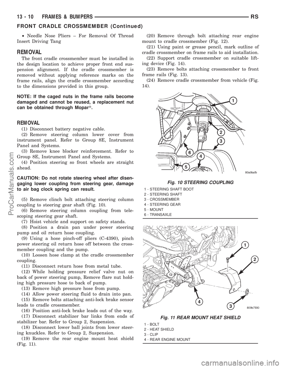
coupling to steering gear shaft (Fig. 10).
(6) Remove steering column coupling from tele-
scoping steering gear shaft.
(7) Hoist vehicle and support on safety stands.
(8) Position a drain pan under power steering
pump and oil return hose coupling.
(9) Using a hose pinch-off pliers (C-4390), pinch
power steering oil return hose off between the cross-
member coupling and the pump.
(10) Loosen hose clamp at the cradle crossmember
coupling.
(11) Disconnect return hose from metal tube.
(12) While holding pressure relief valve nut on
back of power steering pump, Remove flare nut hold-
ing high pressure hose to back of pump.
(13) Remove high pressure hose from pump.
(14) Allow power steering fluid to drain into pan.
(15) Remove bolts attaching anti-lock brake sensor
leads to cradle crossmember.
(16) Position anti-lock brake leads out of the way.
(17) Disconnect stabilizer bar links from ends of
stabilizer bar. Refer to Group 2, Suspension.
(18) Disconnect lower ball joints from lower steer-
ing knuckles. Refer to Group 2, Suspension.
(19) Remove the rear engine mount heat shield
(Fig. 11).(20) Remove through bolt attaching rear engine
mount to cradle crossmember (Fig. 12).
(21) Using paint or grease pencil, mark outline of
cradle crossmember on frame rails to aid installation.
(22) Support cradle crossmember on suitable lift-
ing device (Fig. 14).
(23) Remove bolts attaching crossmember to front
frame rails (Fig. 13).
(24) Remove cradle crossmember from vehicle (Fig.
14).
Fig. 10 STEERING COUPLING
1 - STEERING SHAFT BOOT
2 - STEERING SHAFT
3 - CROSSMEMBER
4 - STEERING GEAR
5 - MOUNT
6 - TRANSAXLE
Fig. 11 REAR MOUNT HEAT SHIELD
1 - BOLT
2 - HEAT SHIELD
3 - CLIP
4 - REAR ENGINE MOUNT
13 - 10 FRAMES & BUMPERSRS
FRONT CRADLE CROSSMEMBER (Continued)
ProCarManuals.com
Page 1474 of 2321
GEAR
TABLE OF CONTENTS
page page
GEAR
DESCRIPTION...........................17
OPERATION.............................17
CAUTION...............................18
REMOVAL..............................18INSTALLATION...........................20
SPECIAL TOOLS.........................21
OUTER TIE ROD END
REMOVAL..............................22
INSTALLATION...........................22
GEAR
DESCRIPTION
This vehicle is equipped with a rack and pinion
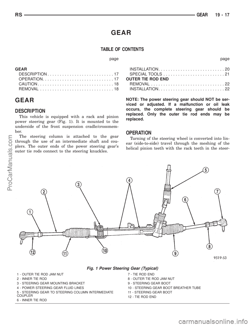
power steering gear (Fig. 1). It is mounted to the
underside of the front suspension cradle/crossmem-
ber.
The steering column is attached to the gear
through the use of an intermediate shaft and cou-
plers. The outer ends of the power steering gear's
outer tie rods connect to the steering knuckles.NOTE: The power steering gear should NOT be ser-
viced or adjusted. If a malfunction or oil leak
occurs, the complete steering gear should be
replaced. Only the outer tie rod ends may be
replaced.
OPERATION
Turning of the steering wheel is converted into lin-
ear (side-to-side) travel through the meshing of the
helical pinion teeth with the rack teeth in the steer-
Fig. 1 Power Steering Gear (Typical)
1 - OUTER TIE ROD JAM NUT
2 - INNER TIE ROD
3 - STEERING GEAR MOUNTING BRACKET
4 - POWER STEERING GEAR FLUID LINES
5 - STEERING GEAR TO STEERING COLUMN INTERMEDIATE
COUPLER
6 - INNER TIE ROD7 - TIE ROD END
8 - OUTER TIE ROD JAM NUT
9 - STEERING GEAR BOOT
10 - STEERING GEAR BOOT BREATHER TUBE
11 - STEERING GEAR BOOT
12 - TIE ROD END
RSGEAR19-17
ProCarManuals.com
Page 1480 of 2321
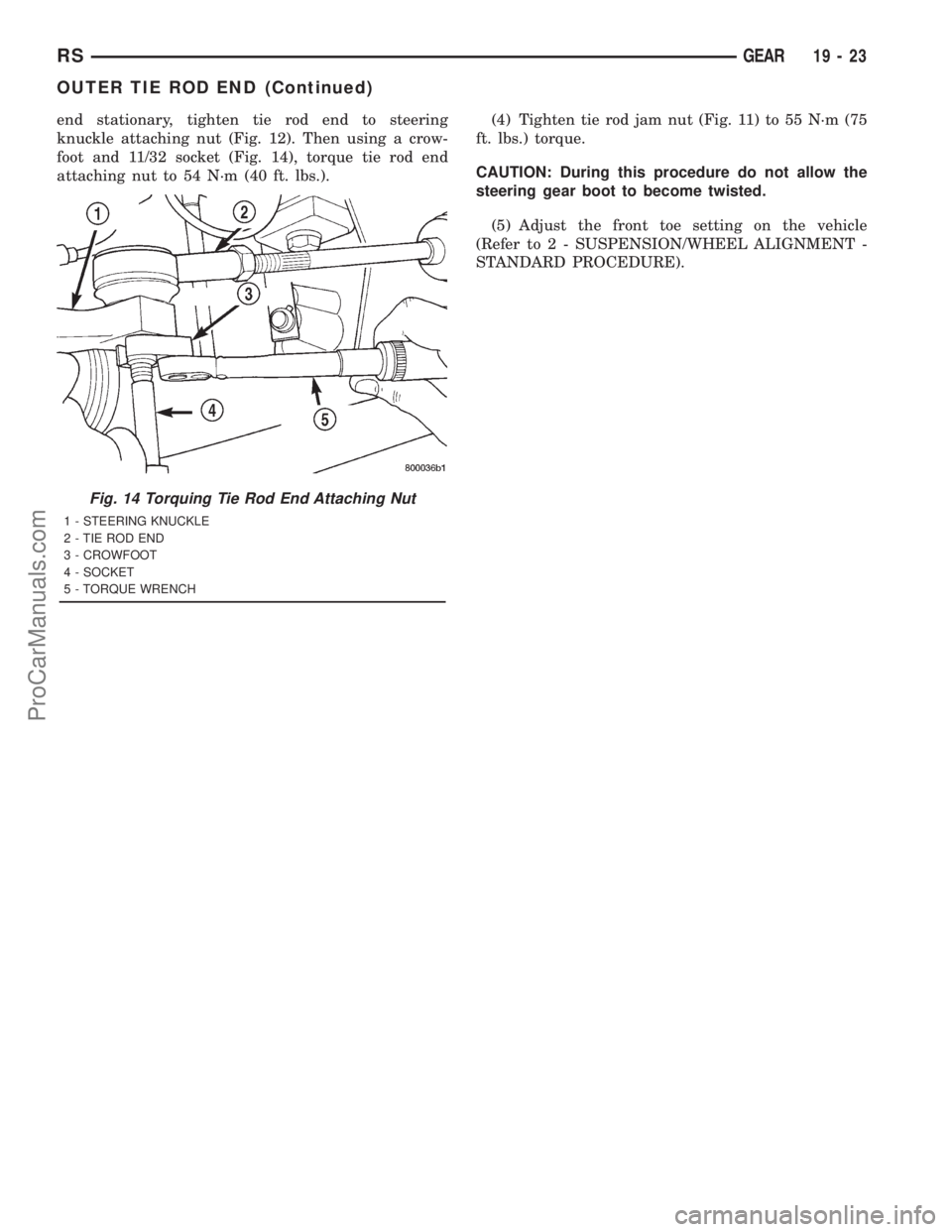
end stationary, tighten tie rod end to steering
knuckle attaching nut (Fig. 12). Then using a crow-
foot and 11/32 socket (Fig. 14), torque tie rod end
attaching nut to 54 N´m (40 ft. lbs.).(4) Tighten tie rod jam nut (Fig. 11) to 55 N´m (75
ft. lbs.) torque.
CAUTION: During this procedure do not allow the
steering gear boot to become twisted.
(5) Adjust the front toe setting on the vehicle
(Refer to 2 - SUSPENSION/WHEEL ALIGNMENT -
STANDARD PROCEDURE).
Fig. 14 Torquing Tie Rod End Attaching Nut
1 - STEERING KNUCKLE
2 - TIE ROD END
3 - CROWFOOT
4 - SOCKET
5 - TORQUE WRENCH
RSGEAR19-23
OUTER TIE ROD END (Continued)
ProCarManuals.com
Page 1800 of 2321
T850 MANUAL TRANSAXLE
TABLE OF CONTENTS
page
T850 MANUAL TRANSAXLE.................1
T850 MANUAL TRANSAXLE
TABLE OF CONTENTS
page page
T850 MANUAL TRANSAXLE
DESCRIPTION............................2
OPERATION.............................4
DIAGNOSIS AND TESTING.................11
DIAGNOSIS AND TESTING - COMMON
PROBLEM CAUSES.....................11
REMOVAL..............................11
DISASSEMBLY...........................17
ASSEMBLY.............................22
INSTALLATION...........................31
SPECIFICATIONS........................37
SPECIAL TOOLS.........................39
AXLE SEALS
REMOVAL..............................42
INSTALLATION...........................42
BACK-UP LAMP SWITCH
REMOVAL..............................43
INSTALLATION...........................43
DIFFERENTIAL
DESCRIPTION...........................43
OPERATION.............................43
DISASSEMBLY...........................44
ASSEMBLY.............................47
ADJUSTMENTS..........................50
FLUID
STANDARD PROCEDURE..................52
STANDARD PROCEDURE - FLUID LEVEL
CHECK...............................52
STANDARD PROCEDURE - FLUID DRAIN
AND FILL.............................53
GEARSHIFT BOOT
REMOVAL..............................53
INSTALLATION...........................53
GEARSHIFT CABLE - CROSSOVER
REMOVAL..............................54INSTALLATION...........................56
ADJUSTMENTS..........................60
GEARSHIFT CABLE - SELECTOR
REMOVAL..............................61
INSTALLATION...........................64
GEARSHIFT KNOB
REMOVAL..............................67
INSTALLATION...........................67
GEARSHIFT MECHANISM
REMOVAL..............................68
INSTALLATION...........................70
INPUT SHAFT
DESCRIPTION...........................73
DISASSEMBLY...........................74
ASSEMBLY.............................77
INTERMEDIATE SHAFT
DESCRIPTION...........................81
DISASSEMBLY...........................81
ASSEMBLY.............................88
SHIFT COVER
DESCRIPTION...........................94
SHIFT FORK AND SHAFT
DESCRIPTION...........................95
SYNCHRONIZER
DESCRIPTION...........................95
DISASSEMBLY...........................95
CLEANING..............................95
INSPECTION............................95
ASSEMBLY.............................95
VEHICLE SPEED SENSOR
REMOVAL..............................96
INSTALLATION...........................96
RGT850 MANUAL TRANSAXLE21a-1
ProCarManuals.com
Page 1852 of 2321
STANDARD PROCEDURE - FLUID DRAIN AND
FILL
NOTE: For proper fluid change intervals, (Refer to
LUBRICATION & MAINTENANCE/MAINTENANCE
SCHEDULES - DESCRIPTION)
The fluid required in this transaxle is Mopart
ATF+4 (Automatic Transmission FluidÐType 9602).
Use of substitute fluids may result in improper
transaxle operation and/or failure.
FLUID DRAIN
(1) Raise vehicle on hoist.
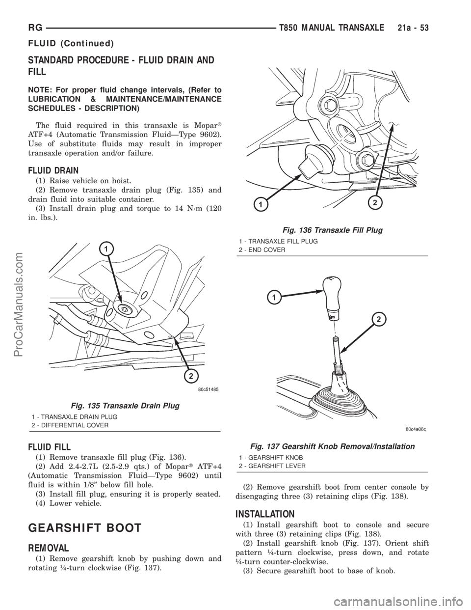
(2) Remove transaxle drain plug (Fig. 135) and
drain fluid into suitable container.
(3) Install drain plug and torque to 14 N´m (120
in. lbs.).
FLUID FILL
(1) Remove transaxle fill plug (Fig. 136).
(2) Add 2.4-2.7L (2.5-2.9 qts.) of MopartATF+4
(Automatic Transmission FluidÐType 9602) until
fluid is within 1/8º below fill hole.
(3) Install fill plug, ensuring it is properly seated.
(4) Lower vehicle.
GEARSHIFT BOOT
REMOVAL
(1) Remove gearshift knob by pushing down and
rotating ò-turn clockwise (Fig. 137).(2) Remove gearshift boot from center console by
disengaging three (3) retaining clips (Fig. 138).
INSTALLATION
(1) Install gearshift boot to console and secure
with three (3) retaining clips (Fig. 138).
(2) Install gearshift knob (Fig. 137). Orient shift
pattern ò-turn clockwise, press down, and rotate
ò-turn counter-clockwise.
(3) Secure gearshift boot to base of knob.
Fig. 135 Transaxle Drain Plug
1 - TRANSAXLE DRAIN PLUG
2 - DIFFERENTIAL COVER
Fig. 136 Transaxle Fill Plug
1 - TRANSAXLE FILL PLUG
2 - END COVER
Fig. 137 Gearshift Knob Removal/Installation
1 - GEARSHIFT KNOB
2 - GEARSHIFT LEVER
RGT850 MANUAL TRANSAXLE21a-53
FLUID (Continued)
ProCarManuals.com