2001 DODGE TOWN AND COUNTRY suspension
[x] Cancel search: suspensionPage 101 of 2321
required adjustment of camber and caster after the
vehicle is built or when servicing the suspension
components. Thus, when performing a wheel align-
ment, caster and camber are not normally considered
adjustable angles. Camber and caster should be
checked to ensure they meet vehicle specifications.
If front camber is found not to meet alignment
specifications, it can be adjusted using an available
camber adjustment bolt package. Before installing a
camber adjustment bolt package on a vehicle found
to be outside the specifications, inspect the suspen-
sion components for any signs of damage or bending.
CAUTION: Do not attempt to adjust the vehicles
wheel; alignment by heating, bending or by per-
forming any other modification to the vehicle's front
suspension components or body.
If camber readings are not within specifications,
use the following procedure to install the front cam-
ber adjustment bolt package and then adjust front
camber.
CAMBER ADJUSTMENT BOLT PACKAGE INSTALLATION
The camber adjustment bolt package contains 2
flange bolts, 2 cam bolts, 2 dog bone washers, and 4
nuts. This package services both sides of the vehicle.
Use the package to attach the strut clevis bracket to
the steering knuckle after the strut clevis bracket
has been modified. To install and adjust the camber
adjustment bolt package, follow the procedure below.
(1) Raise the vehicle until its tires are not support-
ing the weight of the vehicle.
(2) Remove the front tire and wheel assemblies.
CAUTION: When removing the steering knuckle
from the strut clevis bracket, do not put a strain on
the brake flex hose. Also, do not let the weight of
the steering knuckle assembly be supported by the
brake flex hose when removed from the strut
assembly. If necessary use a wire hanger to sup-
port the steering knuckle assembly or if required
remove the brake flex hose from the caliper assem-
bly.
CAUTION: The knuckle to strut assembly attaching
bolt shanks are serrated and must not be turned
during removal. Remove the nuts while holding the
bolts stationary.
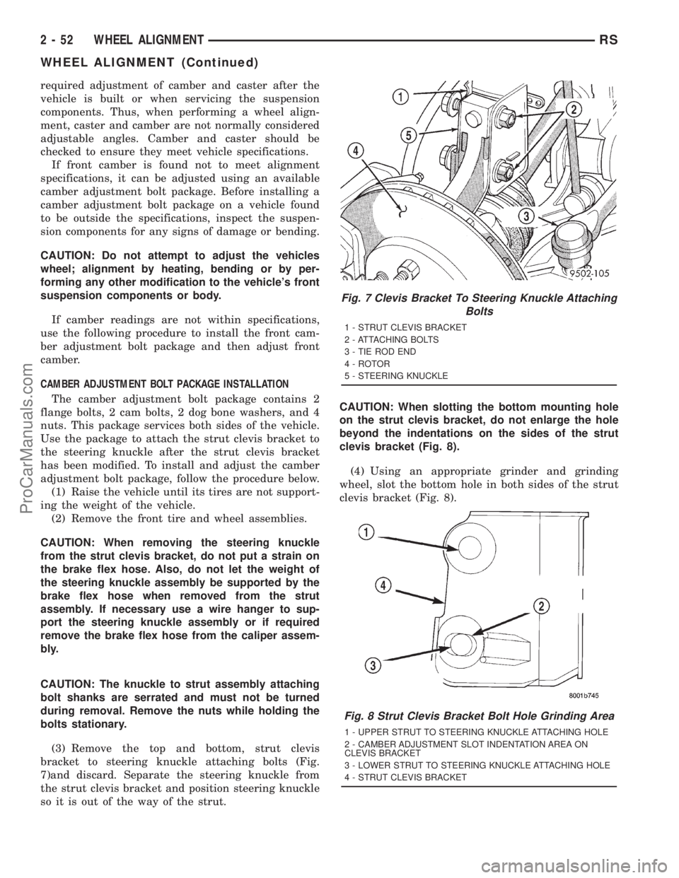
(3) Remove the top and bottom, strut clevis
bracket to steering knuckle attaching bolts (Fig.
7)and discard. Separate the steering knuckle from
the strut clevis bracket and position steering knuckle
so it is out of the way of the strut.CAUTION: When slotting the bottom mounting hole
on the strut clevis bracket, do not enlarge the hole
beyond the indentations on the sides of the strut
clevis bracket (Fig. 8).
(4) Using an appropriate grinder and grinding
wheel, slot the bottom hole in both sides of the strut
clevis bracket (Fig. 8).
Fig. 7 Clevis Bracket To Steering Knuckle Attaching
Bolts
1 - STRUT CLEVIS BRACKET
2 - ATTACHING BOLTS
3 - TIE ROD END
4 - ROTOR
5 - STEERING KNUCKLE
Fig. 8 Strut Clevis Bracket Bolt Hole Grinding Area
1 - UPPER STRUT TO STEERING KNUCKLE ATTACHING HOLE
2 - CAMBER ADJUSTMENT SLOT INDENTATION AREA ON
CLEVIS BRACKET
3 - LOWER STRUT TO STEERING KNUCKLE ATTACHING HOLE
4 - STRUT CLEVIS BRACKET
2 - 52 WHEEL ALIGNMENTRS
WHEEL ALIGNMENT (Continued)
ProCarManuals.com
Page 103 of 2321
CAUTION: Do not twist front inner tie rod to steer-
ing gear rubber boots during front wheel Toe
adjustment.
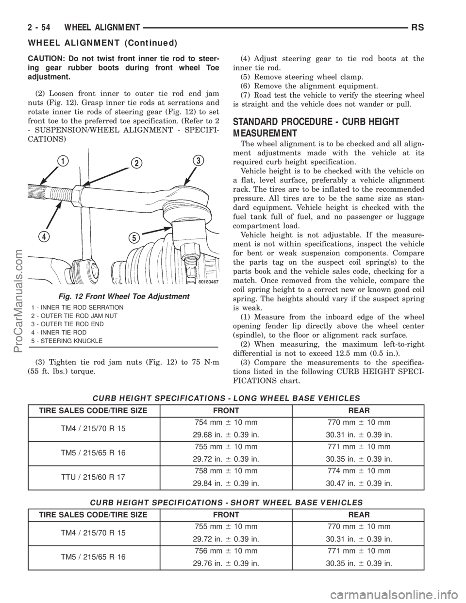
(2) Loosen front inner to outer tie rod end jam
nuts (Fig. 12). Grasp inner tie rods at serrations and
rotate inner tie rods of steering gear (Fig. 12) to set
front toe to the preferred toe specification. (Refer to 2
- SUSPENSION/WHEEL ALIGNMENT - SPECIFI-
CATIONS)
(3) Tighten tie rod jam nuts (Fig. 12) to 75 N´m
(55 ft. lbs.) torque.(4) Adjust steering gear to tie rod boots at the
inner tie rod.
(5) Remove steering wheel clamp.
(6) Remove the alignment equipment.
(7)
Road test the vehicle to verify the steering wheel
is straight and the vehicle does not wander or pull.
STANDARD PROCEDURE - CURB HEIGHT
MEASUREMENT
The wheel alignment is to be checked and all align-
ment adjustments made with the vehicle at its
required curb height specification.
Vehicle height is to be checked with the vehicle on
a flat, level surface, preferably a vehicle alignment
rack. The tires are to be inflated to the recommended
pressure. All tires are to be the same size as stan-
dard equipment. Vehicle height is checked with the
fuel tank full of fuel, and no passenger or luggage
compartment load.
Vehicle height is not adjustable. If the measure-
ment is not within specifications, inspect the vehicle
for bent or weak suspension components. Compare
the parts tag on the suspect coil spring(s) to the
parts book and the vehicle sales code, checking for a
match. Once removed from the vehicle, compare the
coil spring height to a correct new or known good coil
spring. The heights should vary if the suspect spring
is weak.
(1) Measure from the inboard edge of the wheel
opening fender lip directly above the wheel center
(spindle), to the floor or alignment rack surface.
(2) When measuring, the maximum left-to-right
differential is not to exceed 12.5 mm (0.5 in.).
(3) Compare the measurements to the specifica-
tions listed in the following CURB HEIGHT SPECI-
FICATIONS chart.
CURB HEIGHT SPECIFICATIONS - LONG WHEEL BASE VEHICLES
TIRE SALES CODE/TIRE SIZE FRONT REAR
TM4 / 215/70 R 15754 mm610 mm 770 mm610 mm
29.68 in.60.39 in. 30.31 in.60.39 in.
TM5 / 215/65 R 16755 mm610 mm 771 mm610 mm
29.72 in.60.39 in. 30.35 in.60.39 in.
TTU / 215/60 R 17758 mm610 mm 774 mm610 mm
29.84 in.60.39 in. 30.47 in.60.39 in.
CURB HEIGHT SPECIFICATIONS - SHORT WHEEL BASE VEHICLES
TIRE SALES CODE/TIRE SIZE FRONT REAR
TM4 / 215/70 R 15755 mm610 mm 770 mm610 mm
29.72 in.60.39 in. 30.31 in.60.39 in.
TM5 / 215/65 R 16756 mm610 mm 771 mm610 mm
29.76 in.60.39 in. 30.35 in.60.39 in.
Fig. 12 Front Wheel Toe Adjustment
1 - INNER TIE ROD SERRATION
2 - OUTER TIE ROD JAM NUT
3 - OUTER TIE ROD END
4 - INNER TIE ROD
5 - STEERING KNUCKLE
2 - 54 WHEEL ALIGNMENTRS
WHEEL ALIGNMENT (Continued)
ProCarManuals.com
Page 104 of 2321
SPECIFICATIONS
WHEEL ALIGNMENT
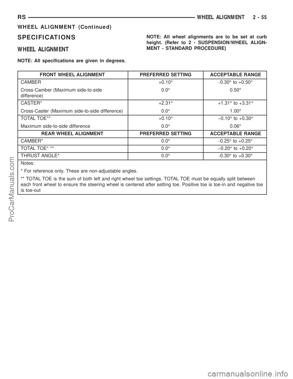
NOTE: All specifications are given in degrees.NOTE: All wheel alignments are to be set at curb
height. (Refer to 2 - SUSPENSION/WHEEL ALIGN-
MENT - STANDARD PROCEDURE)
FRONT WHEEL ALIGNMENT PREFERRED SETTING ACCEPTABLE RANGE
CAMBER +0.10É -0.30É to +0.50É
Cross-Camber (Maximum side-to-side
difference)0.0É 0.50É
CASTER* +2.31É +1.31É to +3.31É
Cross-Caster (Maximum side-to-side difference) 0.0É 1.00É
TOTAL TOE** +0.10É þ0.10É to +0.30É
Maximum side-to-side difference 0.0É 0.06É
REAR WHEEL ALIGNMENT PREFERRED SETTING ACCEPTABLE RANGE
CAMBER* 0.0É -0.25É to +0.25É
TOTAL TOE* ** 0.0É þ0.20É to +0.20É
THRUST ANGLE* 0.0É -0.30É to +0.30É
Notes:
* For reference only. These are non-adjustable angles.
** TOTAL TOE is the sum of both left and right wheel toe settings. TOTAL TOE must be equally split between
each front wheel to ensure the steering wheel is centered after setting toe. Positive toe is toe-in and negative toe
is toe-out
RSWHEEL ALIGNMENT2-55
WHEEL ALIGNMENT (Continued)
ProCarManuals.com
Page 106 of 2321
SUSPENSION
TABLE OF CONTENTS
page page
FRONT SUSPENSION......................1WHEEL ALIGNMENT.......................3
FRONT SUSPENSION
TABLE OF CONTENTS
page page
LOWER BALL JOINT SEAL BOOT
DESCRIPTION............................1REMOVAL...............................1
INSTALLATION............................1
LOWER BALL JOINT SEAL
BOOT
DESCRIPTION
The lower ball joint seal boot is a two piece unit. It
consists of a seal boot and a separate shield that is
located in a groove at the top of the seal boot.
NOTE: The seal boot should only be replaced if
damaged during vehicle service. The entire lower
control arm should be replaced if the joint has been
contaminated.
REMOVAL
(1)Remove steering knuckle from vehicle. (Refer to 2
- SUSPENSION/FRONT/KNUCKLE - REMOVAL)
(2) Remove shield from seal boot by gently pulling
on it.
(3) Using a screw driver or other suitable tool, pry
seal boot off of the lower ball joint.
INSTALLATION
(1) Place a liberal dab of MopartWheel Bearing
Grease around the base of the ball joint stem at the
socket.
(2) Install aNEWseal boot by hand as far as pos-
sible on the ball joint.
CAUTION: Do not use an arbor press to install the
sealing boot on the ball joint. Damage to the seal-
ing boot will occur if excessive pressure is applied
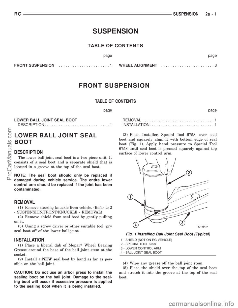
to the sealing boot when it is being installed.(3) Place Installer, Special Tool 6758, over seal
boot and squarely align it with bottom edge of seal
boot (Fig. 1). Apply hand pressure to Special Tool
6758 until seal boot is pressed squarely against top
surface of lower control arm.
(4) Wipe any grease off the ball joint stem.
(5) Place the shield over the top of the seal boot
and stretch it into the groove at the top of the seal
boot.
Fig. 1 Installing Ball Joint Seal Boot (Typical)
1 - SHIELD (NOT ON RG VEHICLE)
2 - SPECIAL TOOL 6758
3 - LOWER CONTROL ARM
4 - BALL JOINT SEAL BOOT
RGSUSPENSION2a-1
ProCarManuals.com
Page 107 of 2321
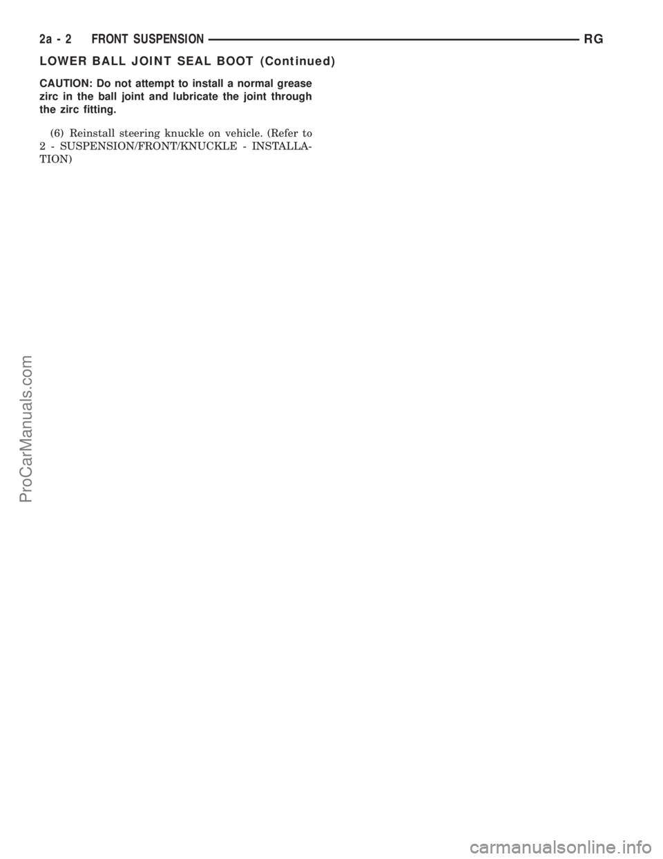
CAUTION: Do not attempt to install a normal grease
zirc in the ball joint and lubricate the joint through
the zirc fitting.
(6) Reinstall steering knuckle on vehicle. (Refer to
2 - SUSPENSION/FRONT/KNUCKLE - INSTALLA-
TION)
2a - 2 FRONT SUSPENSIONRG
LOWER BALL JOINT SEAL BOOT (Continued)
ProCarManuals.com
Page 108 of 2321
WHEEL ALIGNMENT
TABLE OF CONTENTS
page page
WHEEL ALIGNMENT
STANDARD PROCEDURE...................3CURB HEIGHT MEASUREMENT............3
WHEEL ALIGNMENT
STANDARD PROCEDURE - CURB HEIGHT
MEASUREMENT
The wheel alignment is to be checked and all align-
ment adjustments made with the vehicle at its
required curb height specification.
Vehicle height is to be checked with the vehicle on
a flat, level surface, preferably a vehicle alignment
rack. The tires are to be inflated to the recommended
pressure. All tires are to be the same size as stan-
dard equipment. Vehicle height is checked with the
fuel tank full of fuel, and no passenger or luggage
compartment load.
Vehicle height is not adjustable. If the measure-
ment is not within specifications, inspect the vehiclefor bent or weak suspension components. Compare
the parts tag on the suspect coil spring(s) to the
parts book and the vehicle sales code, checking for a
match. Once removed from the vehicle, compare the
coil spring height to a correct new or known good coil
spring. The heights should vary if the suspect spring
is weak.
(1) Measure from the inboard edge of the wheel
opening fender lip directly above the wheel center
(spindle), to the floor or alignment rack surface.
(2) When measuring, the maximum left-to-right
differential is not to exceed 12.5 mm (0.5 in.).
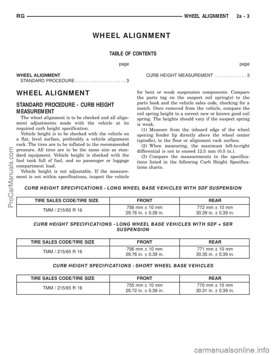
(3) Compare the measurements to the specifica-
tions listed in the following Curb Height Specifica-
tions charts.
CURB HEIGHT SPECIFICATIONS - LONG WHEEL BASE VEHICLES WITH SDF SUSPENSION
TIRE SALES CODE/TIRE SIZE FRONT REAR
TMM / 215/65 R 16756mm 10mm
29.76 in. 0.39 in.772mm 10mm
30.39 in. 0.39 in.
CURB HEIGHT SPECIFICATIONS - LONG WHEEL BASE VEHICLES WITH SDF + SER
SUSPENSION
TIRE SALES CODE/TIRE SIZE FRONT REAR
TMM / 215/65 R 16756mm 10mm
29.76 in. 0.39 in.771mm 10mm
30.35 in. 0.39 in.
CURB HEIGHT SPECIFICATIONS - SHORT WHEEL BASE VEHICLES
TIRE SALES CODE/TIRE SIZE FRONT REAR
TMM / 215/65 R 16755mm 10mm
29.72 in. 0.39 in.770mm 10mm
30.31 in. 0.39 in.
RGWHEEL ALIGNMENT2a-3
ProCarManuals.com
Page 125 of 2321
HALF SHAFT - REAR
TABLE OF CONTENTS
page page
HALF SHAFT - REAR
DESCRIPTION...........................16
DIAGNOSIS AND TESTING.................16
HALF SHAFT..........................16
REMOVAL..............................16INSTALLATION...........................17
SPECIFICATIONS........................18
CV BOOT - INNER/OUTER
REMOVAL..............................18
INSTALLATION...........................20
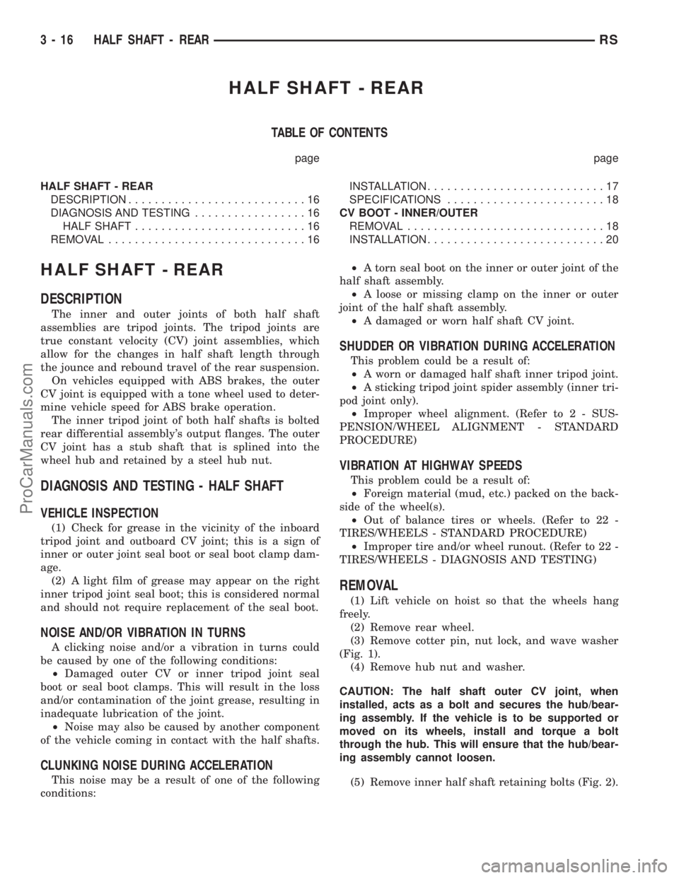
HALF SHAFT - REAR
DESCRIPTION
The inner and outer joints of both half shaft
assemblies are tripod joints. The tripod joints are
true constant velocity (CV) joint assemblies, which
allow for the changes in half shaft length through
the jounce and rebound travel of the rear suspension.
On vehicles equipped with ABS brakes, the outer
CV joint is equipped with a tone wheel used to deter-
mine vehicle speed for ABS brake operation.
The inner tripod joint of both half shafts is bolted
rear differential assembly's output flanges. The outer
CV joint has a stub shaft that is splined into the
wheel hub and retained by a steel hub nut.
DIAGNOSIS AND TESTING - HALF SHAFT
VEHICLE INSPECTION
(1) Check for grease in the vicinity of the inboard
tripod joint and outboard CV joint; this is a sign of
inner or outer joint seal boot or seal boot clamp dam-
age.
(2) A light film of grease may appear on the right
inner tripod joint seal boot; this is considered normal
and should not require replacement of the seal boot.
NOISE AND/OR VIBRATION IN TURNS
A clicking noise and/or a vibration in turns could
be caused by one of the following conditions:
²Damaged outer CV or inner tripod joint seal
boot or seal boot clamps. This will result in the loss
and/or contamination of the joint grease, resulting in
inadequate lubrication of the joint.
²Noise may also be caused by another component
of the vehicle coming in contact with the half shafts.
CLUNKING NOISE DURING ACCELERATION
This noise may be a result of one of the following
conditions:²A torn seal boot on the inner or outer joint of the
half shaft assembly.
²A loose or missing clamp on the inner or outer
joint of the half shaft assembly.
²A damaged or worn half shaft CV joint.
SHUDDER OR VIBRATION DURING ACCELERATION
This problem could be a result of:
²A worn or damaged half shaft inner tripod joint.
²A sticking tripod joint spider assembly (inner tri-
pod joint only).
²Improper wheel alignment. (Refer to 2 - SUS-
PENSION/WHEEL ALIGNMENT - STANDARD
PROCEDURE)
VIBRATION AT HIGHWAY SPEEDS
This problem could be a result of:
²Foreign material (mud, etc.) packed on the back-
side of the wheel(s).
²Out of balance tires or wheels. (Refer to 22 -
TIRES/WHEELS - STANDARD PROCEDURE)
²Improper tire and/or wheel runout. (Refer to 22 -
TIRES/WHEELS - DIAGNOSIS AND TESTING)
REMOVAL
(1) Lift vehicle on hoist so that the wheels hang
freely.
(2) Remove rear wheel.
(3) Remove cotter pin, nut lock, and wave washer
(Fig. 1).
(4) Remove hub nut and washer.
CAUTION: The half shaft outer CV joint, when
installed, acts as a bolt and secures the hub/bear-
ing assembly. If the vehicle is to be supported or
moved on its wheels, install and torque a bolt
through the hub. This will ensure that the hub/bear-
ing assembly cannot loosen.
(5) Remove inner half shaft retaining bolts (Fig. 2).
3 - 16 HALF SHAFT - REARRS
ProCarManuals.com
Page 165 of 2321
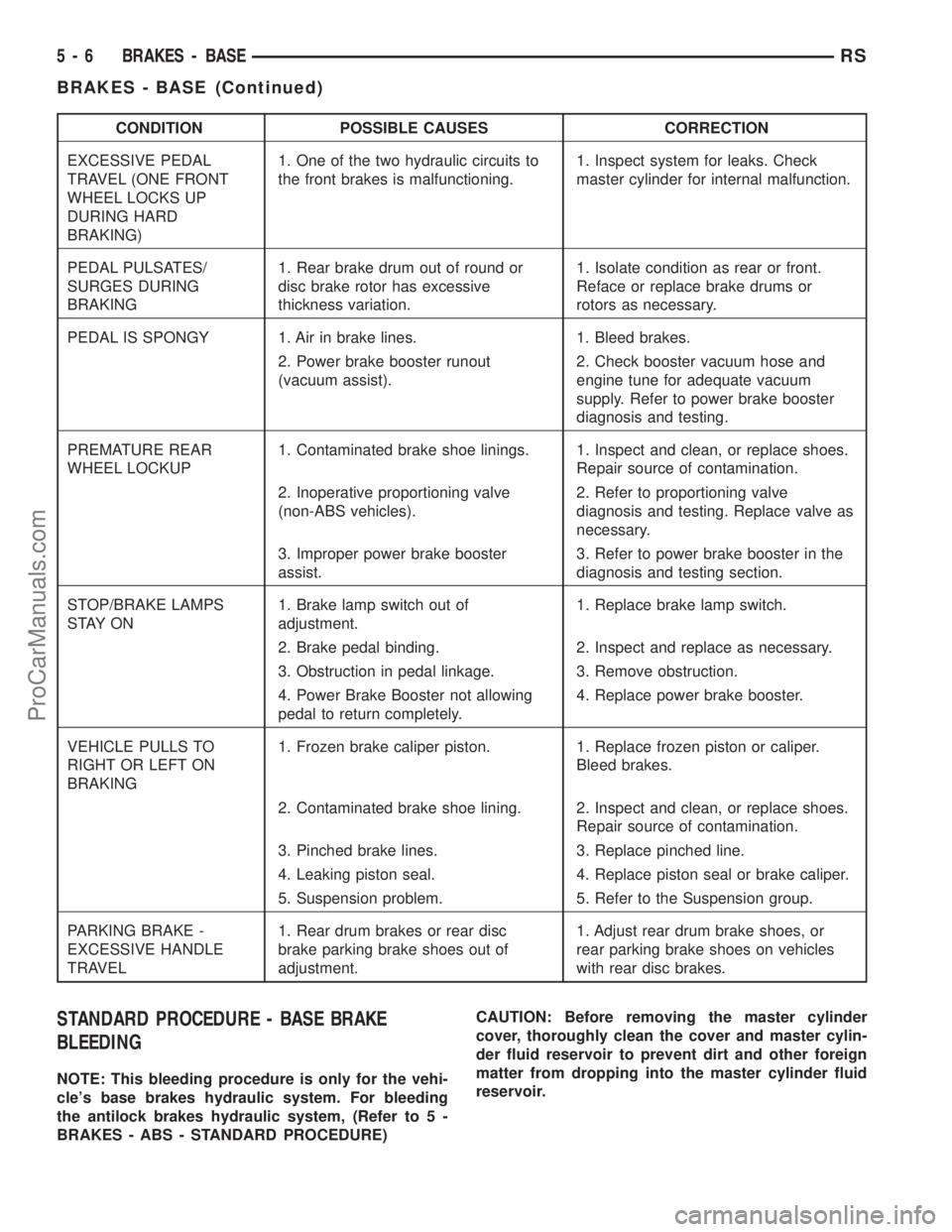
CONDITION POSSIBLE CAUSES CORRECTION
EXCESSIVE PEDAL
TRAVEL (ONE FRONT
WHEEL LOCKS UP
DURING HARD
BRAKING)1. One of the two hydraulic circuits to
the front brakes is malfunctioning.1. Inspect system for leaks. Check
master cylinder for internal malfunction.
PEDAL PULSATES/
SURGES DURING
BRAKING1. Rear brake drum out of round or
disc brake rotor has excessive
thickness variation.1. Isolate condition as rear or front.
Reface or replace brake drums or
rotors as necessary.
PEDAL IS SPONGY 1. Air in brake lines. 1. Bleed brakes.
2. Power brake booster runout
(vacuum assist).2. Check booster vacuum hose and
engine tune for adequate vacuum
supply. Refer to power brake booster
diagnosis and testing.
PREMATURE REAR
WHEEL LOCKUP1. Contaminated brake shoe linings. 1. Inspect and clean, or replace shoes.
Repair source of contamination.
2. Inoperative proportioning valve
(non-ABS vehicles).2. Refer to proportioning valve
diagnosis and testing. Replace valve as
necessary.
3. Improper power brake booster
assist.3. Refer to power brake booster in the
diagnosis and testing section.
STOP/BRAKE LAMPS
S TAY O N1. Brake lamp switch out of
adjustment.1. Replace brake lamp switch.
2. Brake pedal binding. 2. Inspect and replace as necessary.
3. Obstruction in pedal linkage. 3. Remove obstruction.
4. Power Brake Booster not allowing
pedal to return completely.4. Replace power brake booster.
VEHICLE PULLS TO
RIGHT OR LEFT ON
BRAKING1. Frozen brake caliper piston. 1. Replace frozen piston or caliper.
Bleed brakes.
2. Contaminated brake shoe lining. 2. Inspect and clean, or replace shoes.
Repair source of contamination.
3. Pinched brake lines. 3. Replace pinched line.
4. Leaking piston seal. 4. Replace piston seal or brake caliper.
5. Suspension problem. 5. Refer to the Suspension group.
PARKING BRAKE -
EXCESSIVE HANDLE
TRAVEL1. Rear drum brakes or rear disc
brake parking brake shoes out of
adjustment.1. Adjust rear drum brake shoes, or
rear parking brake shoes on vehicles
with rear disc brakes.
STANDARD PROCEDURE - BASE BRAKE
BLEEDING
NOTE: This bleeding procedure is only for the vehi-
cle's base brakes hydraulic system. For bleeding
the antilock brakes hydraulic system, (Refer to 5 -
BRAKES - ABS - STANDARD PROCEDURE)CAUTION: Before removing the master cylinder
cover, thoroughly clean the cover and master cylin-
der fluid reservoir to prevent dirt and other foreign
matter from dropping into the master cylinder fluid
reservoir.
5 - 6 BRAKES - BASERS
BRAKES - BASE (Continued)
ProCarManuals.com