2001 DODGE TOWN AND COUNTRY suspension
[x] Cancel search: suspensionPage 87 of 2321
(3) Position the bushing between the shock
absorber eye and the Driver (Fig. 26). Tighten the
screw drive until the Driver, bushing, and shock
absorber eye are touching and squarely aligned.
(4) Press the bushing into the shock absorber eye
until the Driver bottoms against the face of the eye.
(5) Back off the Ball Joint Press screw drive and
remove the shock absorber from the press.
(6) Install the shock absorber on the vehicle. Refer
to REMOVAL AND INSTALLATION in this section
for the procedure.
INSTALLATION - SHOCK ABSORBER
(1) While holding shock absorber in position
against the frame rail, install the shock absorber
upper mounting bolt.
(2) Install the shock absorber lower mounting bolt
securing the lower end of the shock absorber to the
axle.
(3) Remove the support jack.
(4) Lower the vehicle to the ground so the full curb
weight of the vehicle is supported by the suspension.
(5) Tighten the upper and lower shock absorber
mounting bolt to a torque of 101 N´m (75 ft. lbs.).
SPRING - AWD
DESCRIPTION
The leaf springs used on the rear suspension of
this vehicle are of either a mono-leaf or multi-leaf
design depending on model and options.
Since the rear springs come in various designs and
rates, be sure the correct spring is in use.
OPERATION
The leaf spring controls ride quality and maintains
ride height.
REMOVAL - AWD
(1) Raise vehicle on frame-contact hoist as follows:
(a) Position the hoist arm supporting the corner
of the vehicle to be serviced against a block of wood
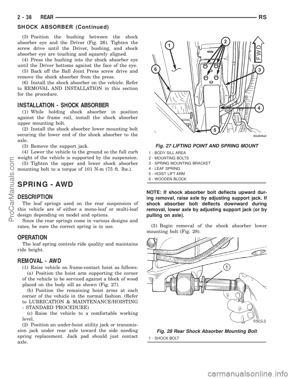
placed on the body sill as shown (Fig. 27).
(b) Position the remaining hoist arms at each
corner of the vehicle in the normal fashion. (Refer
to LUBRICATION & MAINTENANCE/HOISTING
- STANDARD PROCEDURE)
(c) Raise the vehicle to a comfortable working
level.
(2) Position an under-hoist utility jack or transmis-
sion jack under rear axle toward the side needing
spring replacement. Jack pad should just contact
axle.NOTE: If shock absorber bolt deflects upward dur-
ing removal, raise axle by adjusting support jack. If
shock absorber bolt deflects downward during
removal, lower axle by adjusting support jack (or by
pulling on axle).
(3) Begin removal of the shock absorber lower
mounting bolt (Fig. 28).
Fig. 27 LIFTING POINT AND SPRING MOUNT
1 - BODY SILL AREA
2 - MOUNTING BOLTS
3 - SPRING MOUNTING BRACKET
4 - LEAF SPRING
5 - HOIST LIFT ARM
6 - WOODEN BLOCK
Fig. 28 Rear Shock Absorber Mounting Bolt
1 - SHOCK BOLT
2 - 38 REARRS
SHOCK ABSORBER (Continued)
ProCarManuals.com
Page 88 of 2321
(4) Using 2 jack stands positioned under the outer
ends of the axle, raise the axle enough to remove the
weight of the axle from the rear springs.
(5) Loosen and remove the axle plate bolts from
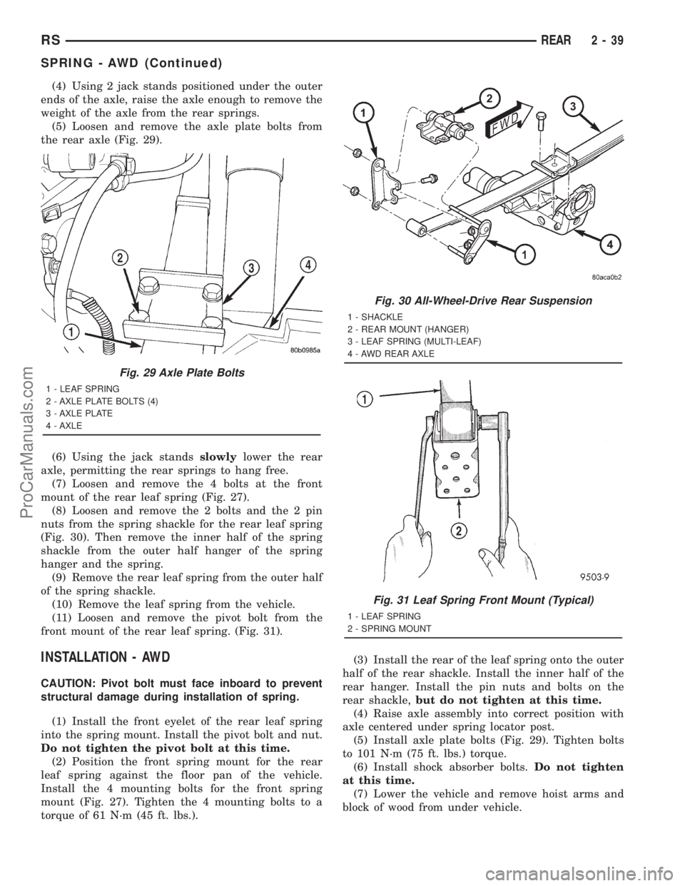
the rear axle (Fig. 29).
(6) Using the jack standsslowlylower the rear
axle, permitting the rear springs to hang free.
(7) Loosen and remove the 4 bolts at the front
mount of the rear leaf spring (Fig. 27).
(8) Loosen and remove the 2 bolts and the 2 pin
nuts from the spring shackle for the rear leaf spring
(Fig. 30). Then remove the inner half of the spring
shackle from the outer half hanger of the spring
hanger and the spring.
(9) Remove the rear leaf spring from the outer half
of the spring shackle.
(10) Remove the leaf spring from the vehicle.
(11) Loosen and remove the pivot bolt from the
front mount of the rear leaf spring. (Fig. 31).
INSTALLATION - AWD
CAUTION: Pivot bolt must face inboard to prevent
structural damage during installation of spring.
(1) Install the front eyelet of the rear leaf spring
into the spring mount. Install the pivot bolt and nut.
Do not tighten the pivot bolt at this time.
(2) Position the front spring mount for the rear
leaf spring against the floor pan of the vehicle.
Install the 4 mounting bolts for the front spring
mount (Fig. 27). Tighten the 4 mounting bolts to a
torque of 61 N´m (45 ft. lbs.).(3) Install the rear of the leaf spring onto the outer
half of the rear shackle. Install the inner half of the
rear hanger. Install the pin nuts and bolts on the
rear shackle,but do not tighten at this time.
(4) Raise axle assembly into correct position with
axle centered under spring locator post.
(5) Install axle plate bolts (Fig. 29). Tighten bolts
to 101 N´m (75 ft. lbs.) torque.
(6) Install shock absorber bolts.Do not tighten
at this time.
(7) Lower the vehicle and remove hoist arms and
block of wood from under vehicle.
Fig. 29 Axle Plate Bolts
1 - LEAF SPRING
2 - AXLE PLATE BOLTS (4)
3 - AXLE PLATE
4 - AXLE
Fig. 30 All-Wheel-Drive Rear Suspension
1 - SHACKLE
2 - REAR MOUNT (HANGER)
3 - LEAF SPRING (MULTI-LEAF)
4 - AWD REAR AXLE
Fig. 31 Leaf Spring Front Mount (Typical)
1 - LEAF SPRING
2 - SPRING MOUNT
RSREAR2-39
SPRING - AWD (Continued)
ProCarManuals.com
Page 89 of 2321
CAUTION: The following sequence must be fol-
lowed when tightening the pin nuts on the rear
hanger for the rear leaf spring. First the hanger pin
nuts must be tightened to the specified torque
shown below. Then tighten the retaining bolts for
the inner to outer half of the spring hanger to the
torque specification listed below. This sequence
must be followed to properly seat the bushings into
the springs and to avoid bending the spring hanger.
(8) Tighten the spring front pivot bolt to 156 N´m
(115 ft. lbs.) torque.
(9) Tighten rear spring shackle pin nuts to 61 N´m
(45 ft. lbs.) torque.
(10) Tighten rear spring shackle inner to outer
half retaining bolts to 61 N´m (45 ft. lbs.) torque.
(11) Tighten the lower shock absorber mounting
bolt to 102 N´m (75 ft. lbs.) torque.
SPRING - FWD
DESCRIPTION
The leaf springs used on the rear suspension of
this vehicle are of either a mono-leaf or multi-leaf
design depending on model and options.
Since the rear springs come in various designs and
rates, be sure the correct spring is in use.
OPERATION
The leaf spring controls ride quality and maintains
ride height.
REMOVAL - FWD
(1) Raise vehicle on frame-contact hoist as follows:
(a) Position the hoist arm supporting the corner
of the vehicle to be serviced against a block of wood
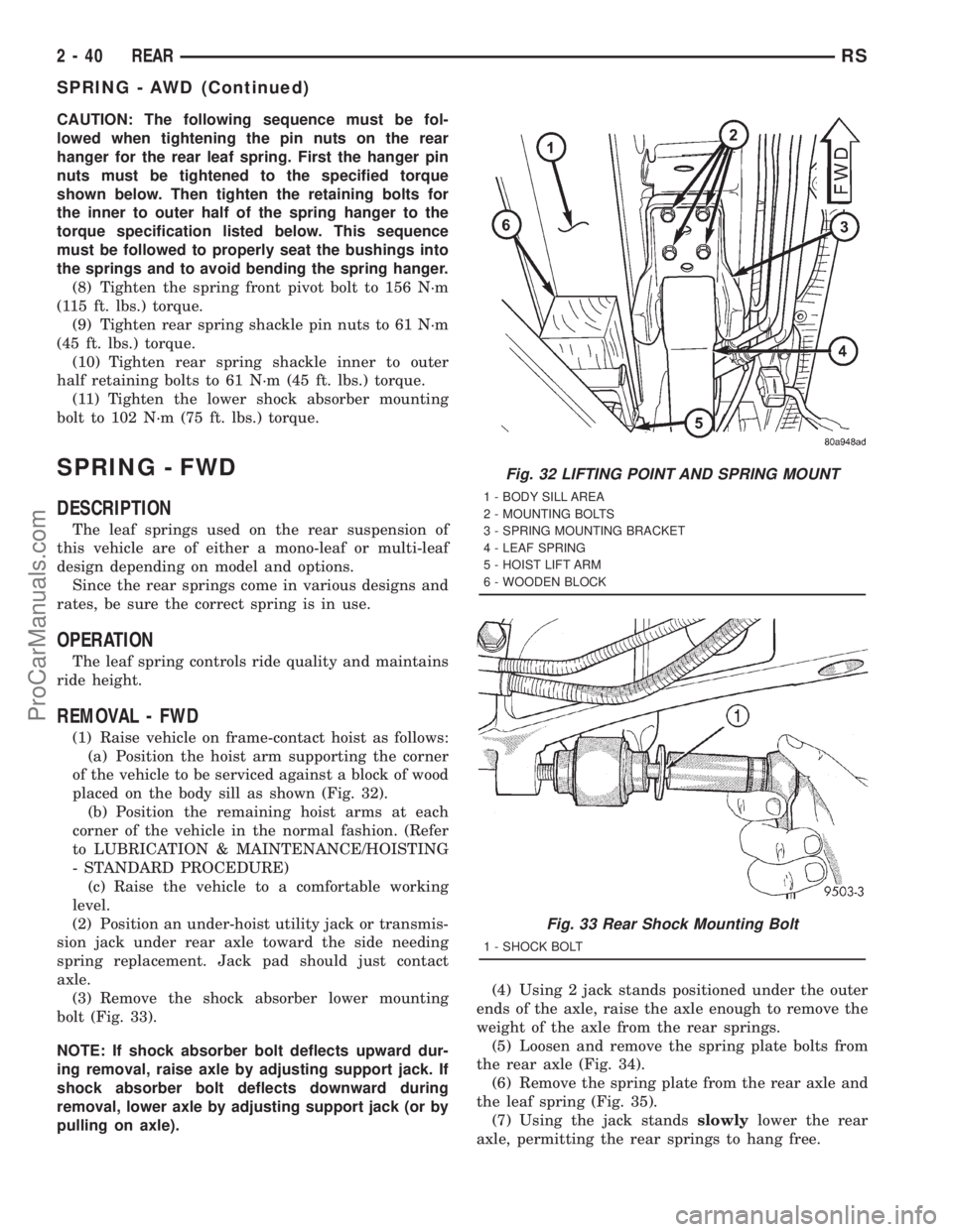
placed on the body sill as shown (Fig. 32).
(b) Position the remaining hoist arms at each
corner of the vehicle in the normal fashion. (Refer
to LUBRICATION & MAINTENANCE/HOISTING
- STANDARD PROCEDURE)
(c) Raise the vehicle to a comfortable working
level.
(2) Position an under-hoist utility jack or transmis-
sion jack under rear axle toward the side needing
spring replacement. Jack pad should just contact
axle.
(3) Remove the shock absorber lower mounting
bolt (Fig. 33).
NOTE: If shock absorber bolt deflects upward dur-
ing removal, raise axle by adjusting support jack. If
shock absorber bolt deflects downward during
removal, lower axle by adjusting support jack (or by
pulling on axle).(4) Using 2 jack stands positioned under the outer
ends of the axle, raise the axle enough to remove the
weight of the axle from the rear springs.
(5) Loosen and remove the spring plate bolts from
the rear axle (Fig. 34).
(6) Remove the spring plate from the rear axle and
the leaf spring (Fig. 35).
(7) Using the jack standsslowlylower the rear
axle, permitting the rear springs to hang free.
Fig. 32 LIFTING POINT AND SPRING MOUNT
1 - BODY SILL AREA
2 - MOUNTING BOLTS
3 - SPRING MOUNTING BRACKET
4 - LEAF SPRING
5 - HOIST LIFT ARM
6 - WOODEN BLOCK
Fig. 33 Rear Shock Mounting Bolt
1 - SHOCK BOLT
2 - 40 REARRS
SPRING - AWD (Continued)
ProCarManuals.com
Page 92 of 2321
shock absorber lower mounting bolt. Do not fully
tighten bolt at this time.
(5) Lower the vehicle and remove hoist arms and
block of wood from under vehicle.
(6) Tighten the spring front pivot bolt to 156 N´m
(115 ft. lbs.) torque.
(7) Tighten the lower shock absorber mounting
bolt to 102 N´m (75 ft. lbs.) torque.
SPRING MOUNTS - REAR
REMOVAL
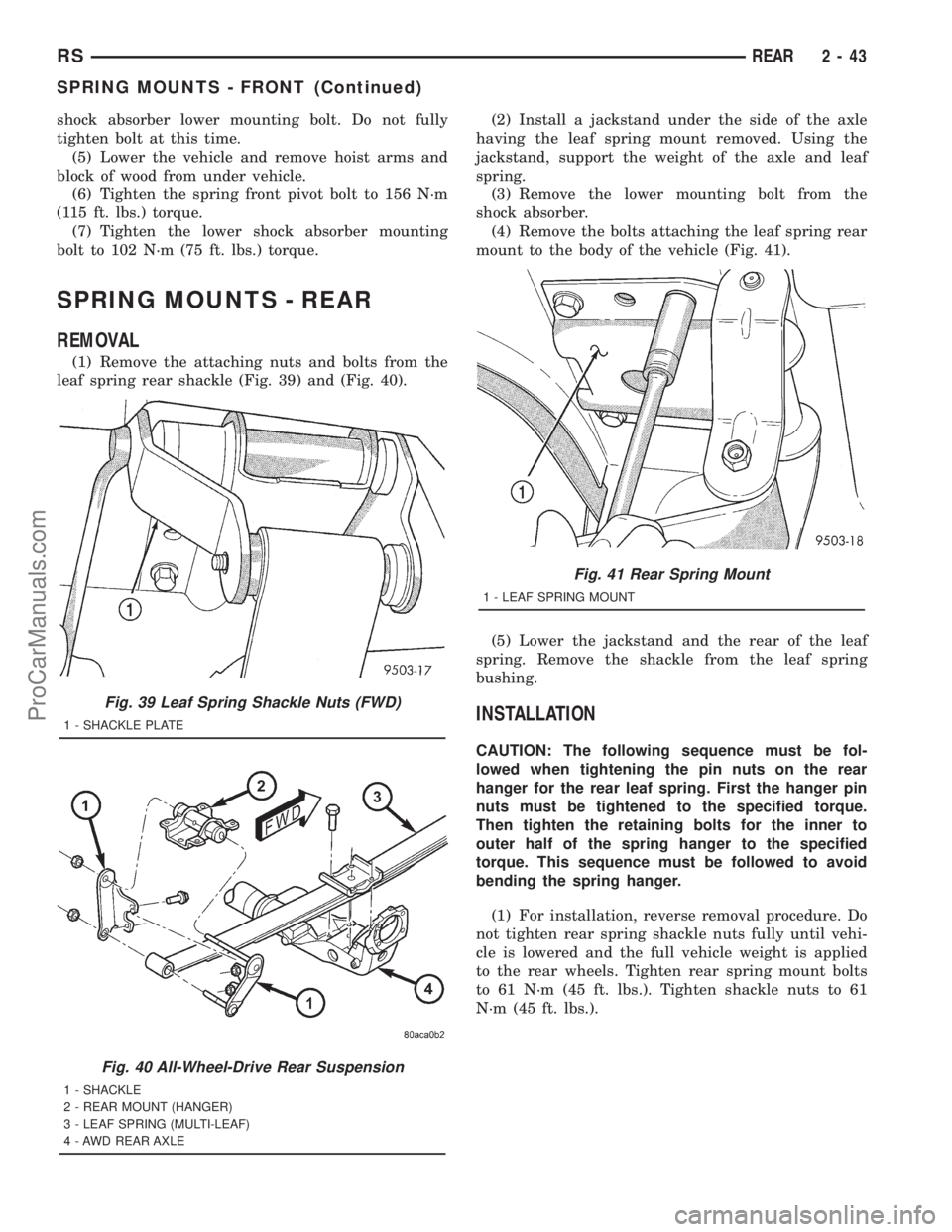
(1) Remove the attaching nuts and bolts from the
leaf spring rear shackle (Fig. 39) and (Fig. 40).(2) Install a jackstand under the side of the axle
having the leaf spring mount removed. Using the
jackstand, support the weight of the axle and leaf
spring.
(3) Remove the lower mounting bolt from the
shock absorber.
(4) Remove the bolts attaching the leaf spring rear
mount to the body of the vehicle (Fig. 41).
(5) Lower the jackstand and the rear of the leaf
spring. Remove the shackle from the leaf spring
bushing.
INSTALLATION
CAUTION: The following sequence must be fol-
lowed when tightening the pin nuts on the rear
hanger for the rear leaf spring. First the hanger pin
nuts must be tightened to the specified torque.
Then tighten the retaining bolts for the inner to
outer half of the spring hanger to the specified
torque. This sequence must be followed to avoid
bending the spring hanger.
(1) For installation, reverse removal procedure. Do
not tighten rear spring shackle nuts fully until vehi-
cle is lowered and the full vehicle weight is applied
to the rear wheels. Tighten rear spring mount bolts
to 61 N´m (45 ft. lbs.). Tighten shackle nuts to 61
N´m (45 ft. lbs.).
Fig. 39 Leaf Spring Shackle Nuts (FWD)
1 - SHACKLE PLATE
Fig. 40 All-Wheel-Drive Rear Suspension
1 - SHACKLE
2 - REAR MOUNT (HANGER)
3 - LEAF SPRING (MULTI-LEAF)
4 - AWD REAR AXLE
Fig. 41 Rear Spring Mount
1 - LEAF SPRING MOUNT
RSREAR2-43
SPRING MOUNTS - FRONT (Continued)
ProCarManuals.com
Page 95 of 2321
WHEEL ALIGNMENT
TABLE OF CONTENTS
page page
WHEEL ALIGNMENT
DESCRIPTION...........................46
DIAGNOSIS AND TESTING.................49
SUSPENSION AND STEERING............49STANDARD PROCEDURE..................51
WHEEL ALIGNMENT....................51
CURB HEIGHT MEASUREMENT...........54
SPECIFICATIONS........................55
WHEEL ALIGNMENT
DESCRIPTION - WHEEL ALIGNMENT
Vehicle wheel alignment is the positioning of all
interrelated front and rear suspension angles. These
angles affect the handling and steering of the vehicle
when it is in motion. Proper wheel alignment is
essential for efficient steering, good directional stabil-
ity, and proper tire wear.
The method of checking a vehicle's front and rear
wheel alignment varies depending on the manufac-
turer and type of equipment used. The manufactur-
er's instructions should always be followed to ensure
accuracy of the alignment, except when
DaimlerChrysler Corporation's wheel alignment spec-
ifications differ.
On this vehicle, the suspension angles that can be
adjusted are as follows:
²Front Camber (with camber bolt package and
standard procedure)
²Front Toe
Check the wheel alignment and make all wheel
alignment adjustments with the vehicle standing at
its proper curb height specification. Curb height is
the normal riding height of the vehicle. It is mea-
sured from a certain point on the vehicle to the
ground or a designated area while the vehicle is sit-
ting on a flat, level surface. Refer to Curb Height
Measurement in this section for additional informa-
tion.
Typical wheel alignment angles and measurements
are described in the following paragraphs.
CAMBER
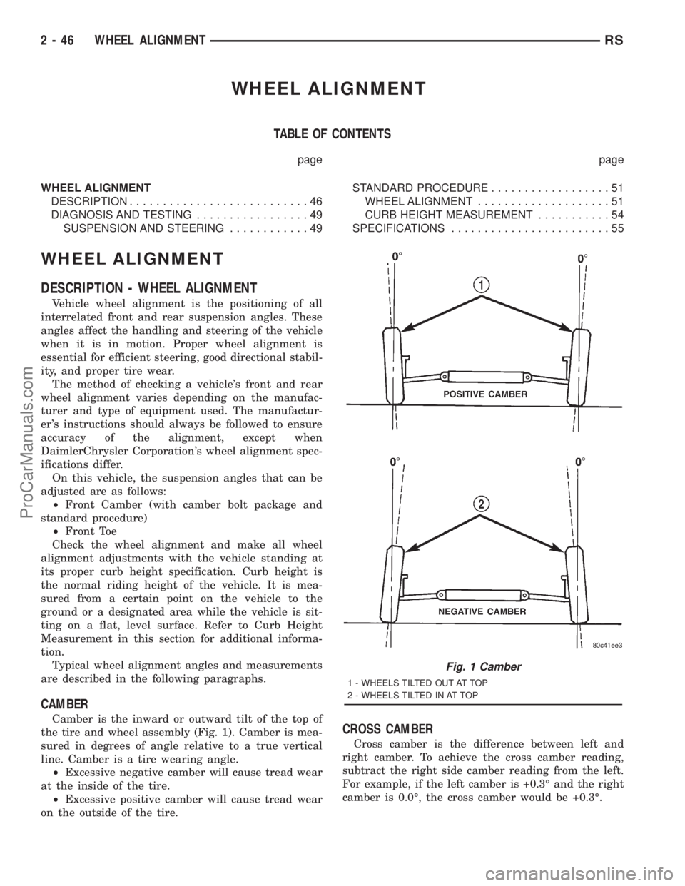
Camber is the inward or outward tilt of the top of
the tire and wheel assembly (Fig. 1). Camber is mea-
sured in degrees of angle relative to a true vertical
line. Camber is a tire wearing angle.
²Excessive negative camber will cause tread wear
at the inside of the tire.
²Excessive positive camber will cause tread wear
on the outside of the tire.CROSS CAMBER
Cross camber is the difference between left and
right camber. To achieve the cross camber reading,
subtract the right side camber reading from the left.
For example, if the left camber is +0.3É and the right
camber is 0.0É, the cross camber would be +0.3É.
Fig. 1 Camber
1 - WHEELS TILTED OUT AT TOP
2 - WHEELS TILTED IN AT TOP
2 - 46 WHEEL ALIGNMENTRS
ProCarManuals.com
Page 97 of 2321
and undue tire wear when steering a vehicle through
a turn.
DYNAMIC TOE PATTERN
Dynamic toe pattern is the inward and outward toe
movement of the front and rear tires through the
suspension's jounce and rebound travel. As the vehi-
cle's suspension moves up and down, the toe pattern
varies. Toe pattern is critical in controlling the direc-
tional stability of the vehicle while in motion. Front
and rear dynamic toe pattern is preset by the factory
at the time the vehicle is assembled.
It is not necessary to check or adjust front or rear
dynamic toe pattern when doing a normal wheel
alignment. The only time dynamic toe pattern needs
to be checked or adjusted is if the frame of the vehi-
cle has been damaged.
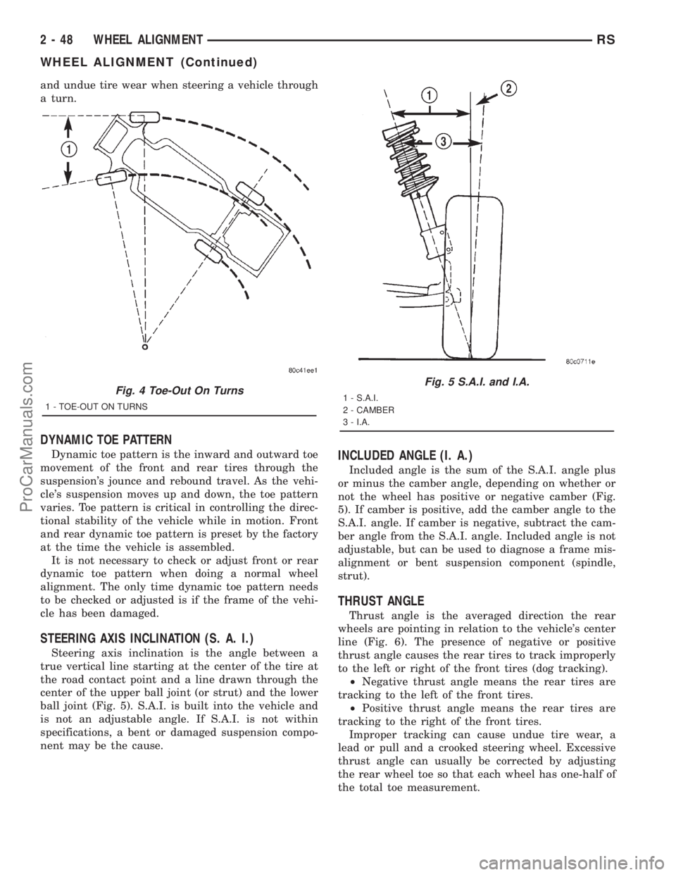
STEERING AXIS INCLINATION (S. A. I.)
Steering axis inclination is the angle between a
true vertical line starting at the center of the tire at
the road contact point and a line drawn through the
center of the upper ball joint (or strut) and the lower
ball joint (Fig. 5). S.A.I. is built into the vehicle and
is not an adjustable angle. If S.A.I. is not within
specifications, a bent or damaged suspension compo-
nent may be the cause.
INCLUDED ANGLE (I. A.)
Included angle is the sum of the S.A.I. angle plus
or minus the camber angle, depending on whether or
not the wheel has positive or negative camber (Fig.
5). If camber is positive, add the camber angle to the
S.A.I. angle. If camber is negative, subtract the cam-
ber angle from the S.A.I. angle. Included angle is not
adjustable, but can be used to diagnose a frame mis-
alignment or bent suspension component (spindle,
strut).
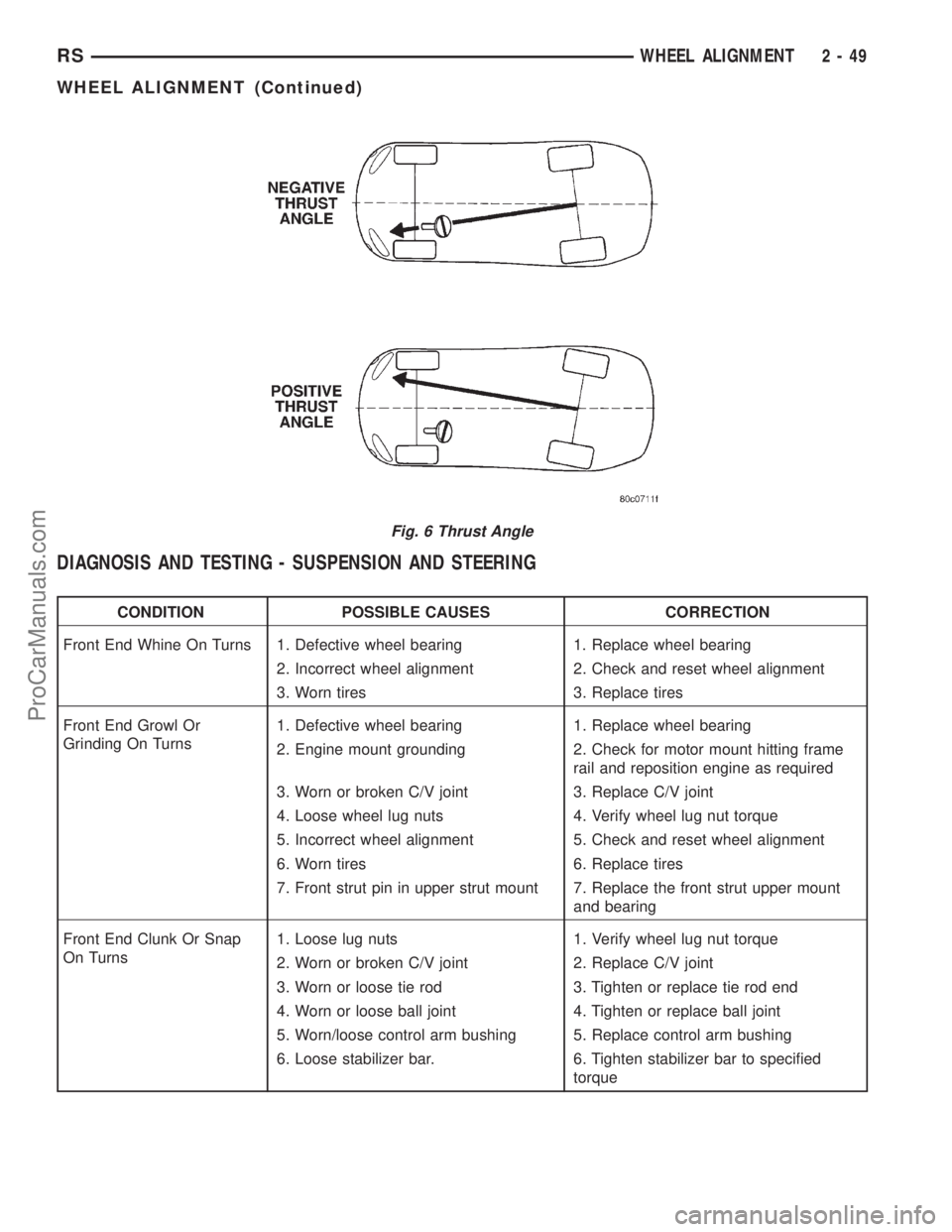
THRUST ANGLE
Thrust angle is the averaged direction the rear
wheels are pointing in relation to the vehicle's center
line (Fig. 6). The presence of negative or positive
thrust angle causes the rear tires to track improperly
to the left or right of the front tires (dog tracking).
²Negative thrust angle means the rear tires are
tracking to the left of the front tires.
²Positive thrust angle means the rear tires are
tracking to the right of the front tires.
Improper tracking can cause undue tire wear, a
lead or pull and a crooked steering wheel. Excessive
thrust angle can usually be corrected by adjusting
the rear wheel toe so that each wheel has one-half of
the total toe measurement.
Fig. 4 Toe-Out On Turns
1 - TOE-OUT ON TURNS
Fig. 5 S.A.I. and I.A.
1 - S.A.I.
2 - CAMBER
3 - I.A.
2 - 48 WHEEL ALIGNMENTRS
WHEEL ALIGNMENT (Continued)
ProCarManuals.com
Page 98 of 2321
DIAGNOSIS AND TESTING - SUSPENSION AND STEERING
CONDITION POSSIBLE CAUSES CORRECTION
Front End Whine On Turns 1. Defective wheel bearing 1. Replace wheel bearing
2. Incorrect wheel alignment 2. Check and reset wheel alignment
3. Worn tires 3. Replace tires
Front End Growl Or
Grinding On Turns1. Defective wheel bearing 1. Replace wheel bearing
2. Engine mount grounding 2. Check for motor mount hitting frame
rail and reposition engine as required
3. Worn or broken C/V joint 3. Replace C/V joint
4. Loose wheel lug nuts 4. Verify wheel lug nut torque
5. Incorrect wheel alignment 5. Check and reset wheel alignment
6. Worn tires 6. Replace tires
7. Front strut pin in upper strut mount 7. Replace the front strut upper mount
and bearing
Front End Clunk Or Snap
On Turns1. Loose lug nuts 1. Verify wheel lug nut torque
2. Worn or broken C/V joint 2. Replace C/V joint
3. Worn or loose tie rod 3. Tighten or replace tie rod end
4. Worn or loose ball joint 4. Tighten or replace ball joint
5. Worn/loose control arm bushing 5. Replace control arm bushing
6. Loose stabilizer bar. 6. Tighten stabilizer bar to specified
torque
Fig. 6 Thrust Angle
RSWHEEL ALIGNMENT2-49
WHEEL ALIGNMENT (Continued)
ProCarManuals.com
Page 100 of 2321
CONDITION POSSIBLE CAUSES CORRECTION
Excessive Steering Free
Play1. Incorrect Steering Gear Adjustment 1. Adjust Or Replace Steering Gear
2. Worn or loose tie rod ends 2. Replace or tighten tie rod ends
3. Loose steering gear mounting bolts 3. Tighten steering gear bolts to specified
torque
4. Loose or worn steering shaft coupler 4. Replace steering shaft coupler
Excessive Steering Effort 1. Low tire pressure 1. Inflate all tires to recommended
pressure
2. Lack of lubricant in steering gear 2. Replace steering gear
3. Low power steering fluid level 3. Fill power steering fluid reservoir to
correct level
4. Loose power steering pump drive
belt4. Correctly adjust power steering pump
drive belt
5. Lack of lubricant in ball joints 5. Lubricate or replace ball joints
6. Steering gear malfunction 6. Replace steering gear
7. Lack of lubricant in steering coupler 7. Replace steering coupler
STANDARD PROCEDURE - WHEEL ALIGNMENT
PRE-WHEEL ALIGNMENT INSPECTION
Before any attempt is made to change or correct
the wheel alignment, the following inspection and
necessary corrections must be made to ensure proper
alignment.
(1) Verify that the fuel tank is full of fuel. If the
tank is not full, the reduction in weight will affect
the curb height of the vehicle and the alignment
angles.
(2) The passenger and luggage compartments of
the vehicle should be free of any load that is not fac-
tory equipment.
(3) Check the tires on the vehicle. All tires must be
the same size and in good condition with approxi-
mately the same amount of tread wear. Inflate all
the tires to the recommended air pressure.
(4) Check the front wheel and tire assemblies for
excessive radial runout.
(5) Inspect lower ball joints and all steering link-
age for looseness, binding, wear or damage. Repair as
necessary.
(6) Check suspension fasteners for proper torque
and retighten as necessary.
(7) Inspect all suspension component rubber bush-
ings for signs of wear or deterioration. Replace any
faulty bushings or components before aligning the
vehicle.
(8) Check the vehicle's curb height to verify it is
within specifications. Refer to Curb Height Measure-
ment.
WHEEL ALIGNMENT SETUP
(1) Position the vehicle on an alignment rack.
(2) Install all required alignment equipment on
the vehicle per the alignment equipment manufactur-
er's instructions. On this vehicle, a four-wheel align-
ment is recommended.
NOTE: Prior to reading the vehicle's alignment
readouts, the front and rear of vehicle should be
jounced. Induce jounce (rear first, then front) by
grasping the center of the bumper and jouncing
each end of vehicle an equal number of times. The
bumper should always be released when vehicle is
at the bottom of the jounce cycle.
(3) Read the vehicle's current front and rear align-
ment settings. Compare the vehicle's current align-
ment settings to the vehicle specifications for camber,
caster and toe-in. (Refer to 2 - SUSPENSION/
WHEEL ALIGNMENT - SPECIFICATIONS)
(4) If front camber and caster are not within spec-
ifications, proceed to CAMBER AND CASTER below.
If caster and camber are within specifications, pro-
ceed to TOE which can be found following CAMBER
AND CASTER. Rear camber, caster and toe are not
adjustable. If found not to be within specifications,
reinspect for damaged suspension or body compo-
nents and replace as necessary.
CAMBER AND CASTER
Camber and caster settings on this vehicle are
determined at the time the vehicle is designed, by
the location of the vehicle's suspension components.
This is referred to as NET BUILD. The result is no
RSWHEEL ALIGNMENT2-51
WHEEL ALIGNMENT (Continued)
ProCarManuals.com