2001 DODGE TOWN AND COUNTRY differential
[x] Cancel search: differentialPage 1510 of 2321
INPUT SHAFT COVER SEAL
REMOVAL
The power transfer unit input shaft cover seal is
the larger of the two seals located on the inside of
the end cover. The differential bearing cup must be
removed to service this seal.
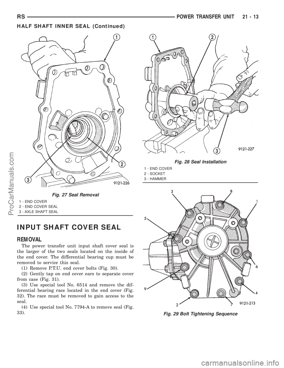
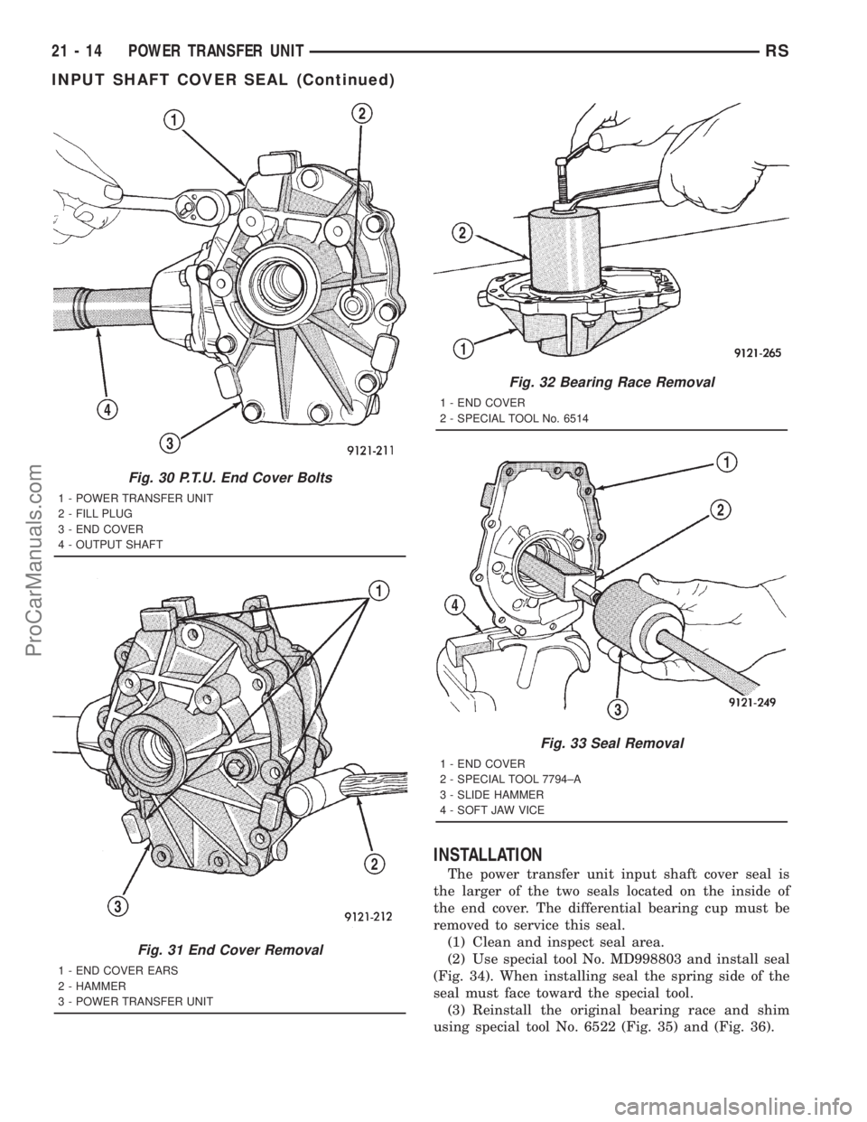
(1) Remove P.T.U. end cover bolts (Fig. 30).
(2) Gently tap on end cover ears to separate cover
from case (Fig. 31).
(3) Use special tool No. 6514 and remove the dif-
ferential bearing race located in the end cover (Fig.
32). The race must be removed to gain access to the
seal.
(4) Use special tool No. 7794-A to remove seal (Fig.
33).
Fig. 27 Seal Removal
1 - END COVER
2 - END COVER SEAL
3 - AXLE SHAFT SEAL
Fig. 28 Seal Installation
1 - END COVER
2 - SOCKET
3 - HAMMER
Fig. 29 Bolt Tightening Sequence
RSPOWER TRANSFER UNIT21-13
HALF SHAFT INNER SEAL (Continued)
ProCarManuals.com
Page 1511 of 2321
INSTALLATION
The power transfer unit input shaft cover seal is
the larger of the two seals located on the inside of
the end cover. The differential bearing cup must be
removed to service this seal.
(1) Clean and inspect seal area.
(2) Use special tool No. MD998803 and install seal
(Fig. 34). When installing seal the spring side of the
seal must face toward the special tool.
(3) Reinstall the original bearing race and shim
using special tool No. 6522 (Fig. 35) and (Fig. 36).
Fig. 30 P.T.U. End Cover Bolts
1 - POWER TRANSFER UNIT
2 - FILL PLUG
3 - END COVER
4 - OUTPUT SHAFT
Fig. 31 End Cover Removal
1 - END COVER EARS
2 - HAMMER
3 - POWER TRANSFER UNIT
Fig. 32 Bearing Race Removal
1 - END COVER
2 - SPECIAL TOOL No. 6514
Fig. 33 Seal Removal
1 - END COVER
2 - SPECIAL TOOL 7794±A
3 - SLIDE HAMMER
4 - SOFT JAW VICE
21 - 14 POWER TRANSFER UNITRS
INPUT SHAFT COVER SEAL (Continued)
ProCarManuals.com
Page 1519 of 2321
REMOVAL.............................118
INSTALLATION..........................118
THROTTLE VALVE CABLE
REMOVAL.............................118
INSTALLATION..........................118
ADJUSTMENTS.........................120
TORQUE CONVERTER
DESCRIPTION..........................120
OPERATION............................123
REMOVAL.............................125
INSTALLATION..........................125
TRANSFER SYSTEM - OUTPUT SHAFT/GEAR/
BEARING
REMOVAL.............................126
INSTALLATION..........................129
ADJUSTMENTS.........................132TRANSFER SYSTEM - TRANSFER SHAFT/
GEAR/BEARING
REMOVAL.............................134
INSTALLATION..........................137
ADJUSTMENTS.........................142
VALVE BODY
REMOVAL.............................142
DISASSEMBLY..........................145
CLEANING.............................151
INSPECTION...........................152
ASSEMBLY............................152
INSTALLATION..........................155
ADJUSTMENTS.........................157
VEHICLE SPEED SENSOR/PINION GEAR
REMOVAL.............................157
INSTALLATION..........................157
AUTOMATIC - 31TH
DESCRIPTION
This transaxle combines torque converter, three
speed transmission, final drive gearing, and differen-
tial into a front wheel drive system.
Within this transaxle, there are three primary
areas:
(1) Main center line plus valve body.
(2) Transfer shaft center line (includes governor
and parking sprag).
(3) Differential center line.
Center distances between the main rotating parts
in these three areas are held precise to maintain a
low noise level.
The torque converter, transaxle area, and differen-
tial are housed in an integral aluminum die casting.
The differential oil sump is common with the
transaxle sump. Separate filling of the differen-
tial is NOT necessary.
The torque converter is attached to the crankshaft
through a flexible driving plate. Cooling of the con-
verter is accomplished by circulating the transaxle
fluid through a remote cooler. There are two types of
coolers used. An oil-to-water type cooler located in
the radiator side tank and/or an oil-to-air heat
exchanger. The torque converter assembly is a sealed
unit that cannot be disassembled.
The transaxle fluid is filtered by an internal filter
attached to the lower side of the valve body assembly.Engine torque is transmitted to the torque con-
verter and then through the input shaft to multiple-
disc clutches in the transaxle. The power flow
depends on the application of the clutches and bands.
Refer to Elements in Use Chart in Diagnosis and
Tests section.
The transaxle consists of:
²Two multiple-disc clutches
²An overrunning clutch
²Two servos
²A hydraulic accumulator
²Two bands
²Two planetary gear sets
This provides three forward ratios and a reverse
ratio. The common sun gear of the planetary gear
sets is connected to the front clutch by a driving
shell. The driving shell is splined to the sun gear and
front clutch retainer. The hydraulic system consists
of an oil pump and a single valve body which con-
tains all of the valves except the governor valves.
The transaxle sump and differential sump are both
vented through the dipstick. Output torque from the
main center line is delivered through helical gears to
the transfer shaft. This gear set is a factor in the
transaxle final drive (axle) ratio. The shaft also car-
ries the governor and parking sprag. An integral heli-
cal gear on the transfer shaft drives the differential
ring gear.
21 - 22 AUTOMATIC - 31THRS
ProCarManuals.com
Page 1520 of 2321
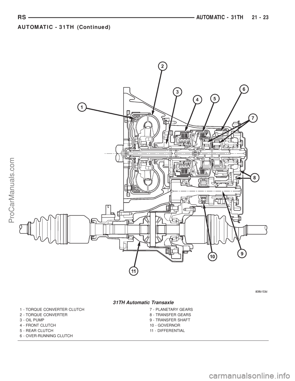
31TH Automatic Transaxle
1 - TORQUE CONVERTER CLUTCH
2 - TORQUE CONVERTER
3 - OIL PUMP
4 - FRONT CLUTCH
5 - REAR CLUTCH
6 - OVER-RUNNING CLUTCH7 - PLANETARY GEARS
8 - TRANSFER GEARS
9 - TRANSFER SHAFT
10 - GOVERNOR
11 - DIFFERENTIAL
RSAUTOMATIC - 31TH21-23
AUTOMATIC - 31TH (Continued)
ProCarManuals.com
Page 1529 of 2321
The process of elimination can be used to detect
any unit that slips and to confirm proper operation of
good units. Road testing can usually diagnose slip-
ping units, although the actual cause of the problem
may not be detected. Practically any condition can be
caused by leaking hydraulic circuits or sticking
valves.
Therefore, unless the condition is obvious, the
transaxle should never be disassembled until hydrau-
lic pressure tests have been performed.DIAGNOSIS AND TESTING - HYDRAULIC
PRESSURE TESTS
Pressure testing is a very important step in the
diagnostic procedure. These tests usually reveal the
cause of most transaxle problems.
Before performing pressure tests, check fluid level
and condition, as well as control cable adjustments.
Fluid must be at operating temperature (150-200
degrees F.).
Install an engine tachometer. Raise vehicle on a
hoist that allows front wheels to turn, and position
tachometer so it can be read.
Disconnect throttle cable and shift cable from
transaxle levers so they can be controlled from out-
side the vehicle.
Attach 100 psi gauges (C-3292) to ports required
for test being conducted. A 300 psi gauge (C-3293SP)
is required for reverse pressure test at rear servo.
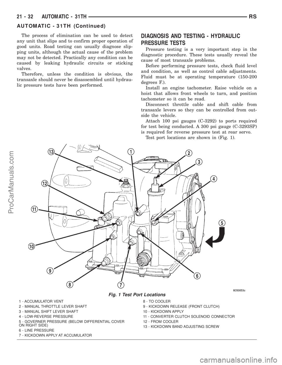
Test port locations are shown in (Fig. 1).
Fig. 1 Test Port Locations
1 - ACCUMULATOR VENT
2 - MANUAL THROTTLE LEVER SHAFT
3 - MANUAL SHIFT LEVER SHAFT
4 - LOW-REVERSE PRESSURE
5 - GOVERNER PRESSURE (BELOW DIFFERENTIAL COVER
ON RIGHT SIDE)
6 - LINE PRESSURE
7 - KICKDOWN APPLY AT ACCUMULATOR8 - TO COOLER
9 - KICKDOWN RELEASE (FRONT CLUTCH)
10 - KICKDOWN APPLY
11 - CONVERTER CLUTCH SOLENOID CONNECTOR
12 - FROM COOLER
13 - KICKDOWN BAND ADJUSTING SCREW
21 - 32 AUTOMATIC - 31THRS
AUTOMATIC - 31TH (Continued)
ProCarManuals.com
Page 1531 of 2321
(5) Low line pressure in all positions indicates a
defective pump, a clogged filter, or a stuck pressure
regulator valve.
GOVERNOR PRESSURE
Test only if transaxle shifts at wrong vehicle
speeds when throttle cable is correctly adjusted.
(1) Connect a 100 psi gauge to governor pressure
port. It is located at lower right side of case, below
differential cover (Fig. 2).
(2) Operate transaxle in third gear to read pres-
sures. The governor pressure should respond
smoothly to changes in mph and should return to 0
to 3 psi when vehicle is stopped. High pressure
(above 3 psi) at standstill will prevent the transaxle
from downshifting.
THROTTLE PRESSURE
No gauge port is provided for throttle pressure.
Incorrect throttle pressure should be suspected if
part throttle upshift speeds are either delayed or
occur too early in relation to vehicle speed. Engine
runaway on shifts can also be an indicator of low
throttle pressure setting, or misadjusted throttle
cable.
In no case should throttle pressure be adjusted
until the transaxle throttle cable adjustment has
been verified to be correct.
DIAGNOSIS AND TESTING - TORQUE
CONVERTER HOUSING FLUID LEAKAGE
When diagnosing converter housing fluid leaks,
three actions must be taken before repair:
(1) Verify proper transmission fluid level.
(2) Verify that the leak originates from the con-
verter housing area and is transmission fluid.
(3) Determine the true source of the leak.
Fluid leakage at or around the torque converter
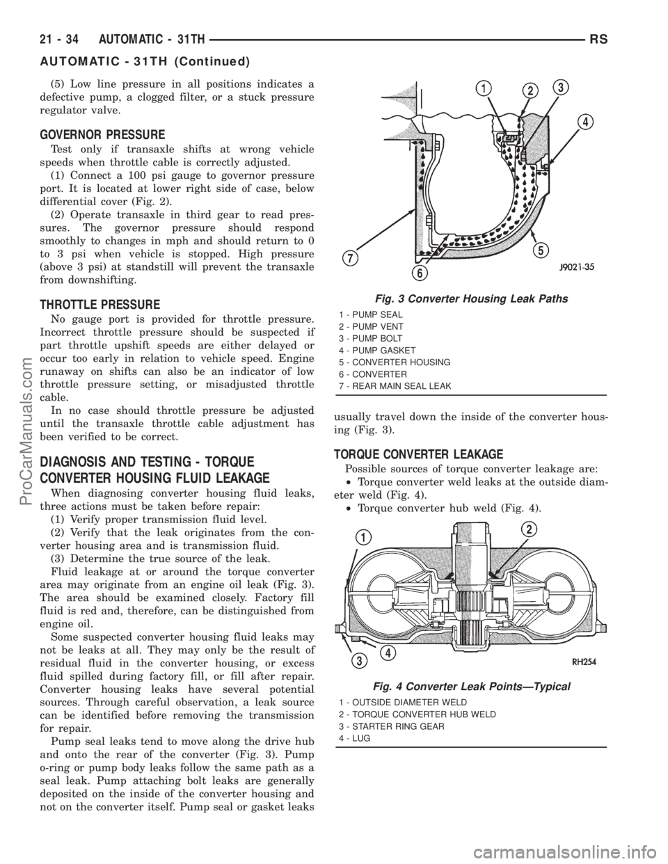
area may originate from an engine oil leak (Fig. 3).
The area should be examined closely. Factory fill
fluid is red and, therefore, can be distinguished from
engine oil.
Some suspected converter housing fluid leaks may
not be leaks at all. They may only be the result of
residual fluid in the converter housing, or excess
fluid spilled during factory fill, or fill after repair.
Converter housing leaks have several potential
sources. Through careful observation, a leak source
can be identified before removing the transmission
for repair.
Pump seal leaks tend to move along the drive hub
and onto the rear of the converter (Fig. 3). Pump
o-ring or pump body leaks follow the same path as a
seal leak. Pump attaching bolt leaks are generally
deposited on the inside of the converter housing and
not on the converter itself. Pump seal or gasket leaksusually travel down the inside of the converter hous-
ing (Fig. 3).
TORQUE CONVERTER LEAKAGE
Possible sources of torque converter leakage are:
²Torque converter weld leaks at the outside diam-
eter weld (Fig. 4).
²Torque converter hub weld (Fig. 4).
Fig. 3 Converter Housing Leak Paths
1 - PUMP SEAL
2 - PUMP VENT
3 - PUMP BOLT
4 - PUMP GASKET
5 - CONVERTER HOUSING
6 - CONVERTER
7 - REAR MAIN SEAL LEAK
Fig. 4 Converter Leak PointsÐTypical
1 - OUTSIDE DIAMETER WELD
2 - TORQUE CONVERTER HUB WELD
3 - STARTER RING GEAR
4 - LUG
21 - 34 AUTOMATIC - 31THRS
AUTOMATIC - 31TH (Continued)
ProCarManuals.com
Page 1536 of 2321
DISASSEMBLY
CAUTION: If transaxle failure has occured, it is nec-
essary to flush the transaxle oil cooler and lines to
remove debris and particles that could contaminate
and/or fail a new or rebuilt unit. (Refer to 7 - COOL-
ING/TRANSMISSION - STANDARD PROCEDURE)
NOTE: This procedure does not include disassem-
bly of final drive (differential) components. (Refer to
21 - TRANSMISSION/TRANSAXLE/AUTOMATIC -
31TH/FINAL DRIVE - DISASSEMBLY)
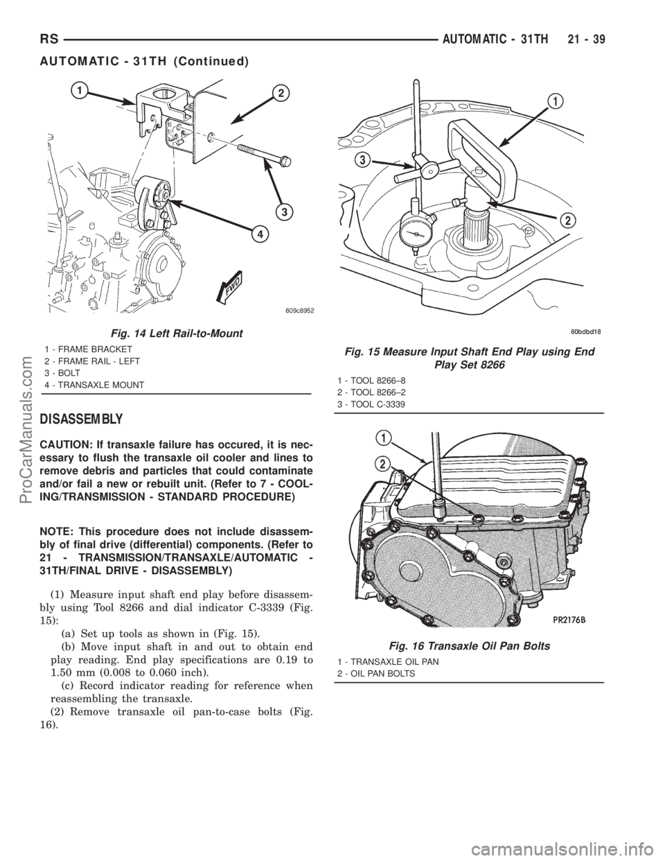
(1) Measure input shaft end play before disassem-
bly using Tool 8266 and dial indicator C-3339 (Fig.
15):
(a) Set up tools as shown in (Fig. 15).
(b) Move input shaft in and out to obtain end
play reading. End play specifications are 0.19 to
1.50 mm (0.008 to 0.060 inch).
(c) Record indicator reading for reference when
reassembling the transaxle.
(2) Remove transaxle oil pan-to-case bolts (Fig.
16).
Fig. 14 Left Rail-to-Mount
1 - FRAME BRACKET
2 - FRAME RAIL - LEFT
3 - BOLT
4 - TRANSAXLE MOUNTFig. 15 Measure Input Shaft End Play using End
Play Set 8266
1 - TOOL 8266±8
2 - TOOL 8266±2
3 - TOOL C-3339
Fig. 16 Transaxle Oil Pan Bolts
1 - TRANSAXLE OIL PAN
2 - OIL PAN BOLTS
RSAUTOMATIC - 31TH21-39
AUTOMATIC - 31TH (Continued)
ProCarManuals.com
Page 1543 of 2321
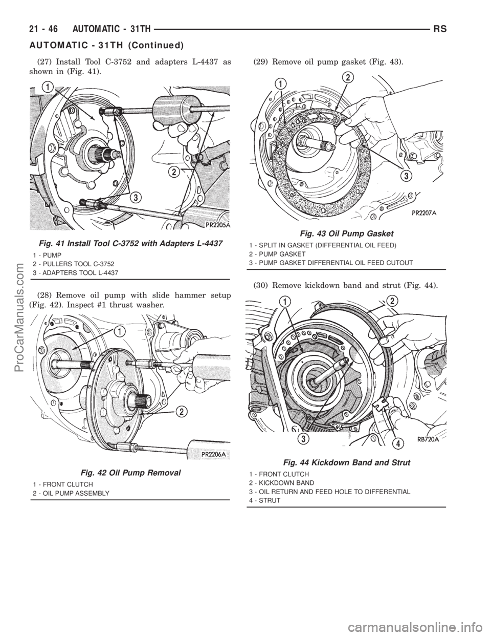
(27) Install Tool C-3752 and adapters L-4437 as
shown in (Fig. 41).
(28) Remove oil pump with slide hammer setup
(Fig. 42). Inspect #1 thrust washer.(29) Remove oil pump gasket (Fig. 43).
(30) Remove kickdown band and strut (Fig. 44).
Fig. 41 Install Tool C-3752 with Adapters L-4437
1 - PUMP
2 - PULLERS TOOL C-3752
3 - ADAPTERS TOOL L-4437
Fig. 42 Oil Pump Removal
1 - FRONT CLUTCH
2 - OIL PUMP ASSEMBLY
Fig. 43 Oil Pump Gasket
1 - SPLIT IN GASKET (DIFFERENTIAL OIL FEED)
2 - PUMP GASKET
3 - PUMP GASKET DIFFERENTIAL OIL FEED CUTOUT
Fig. 44 Kickdown Band and Strut
1 - FRONT CLUTCH
2 - KICKDOWN BAND
3 - OIL RETURN AND FEED HOLE TO DIFFERENTIAL
4 - STRUT
21 - 46 AUTOMATIC - 31THRS
AUTOMATIC - 31TH (Continued)
ProCarManuals.com