2001 DODGE TOWN AND COUNTRY ignition
[x] Cancel search: ignitionPage 380 of 2321
SKIM is properly installed on the steering column,
the antenna ring fits snugly around the circumfer-
ence of the ignition lock cylinder housing. If this ring
is not mounted properly, communication problems
may arise in the form of transponder-related faults.
For added system security, each SKIM is pro-
grammed with a unique9Secret Key9code. This code
is stored in memory and is sent over the PCI bus to
the PCM and to each key that is programmed to
work with the vehicle. The9Secret Key9code is there-
fore a common element found in all components of
the Sentry Key Immobilizer System (SKIS). In the
event that a SKIM replacement is required, the
9Secret Key9code can be restored from the PCM by
following the SKIM replacement procedure found in
the DRB IIItscan tool. Proper completion of this
task will allow the existing ignition keys to be repro-
grammed. Therefore, new keys will NOT be needed.
In the event that the original9Secret Key9code can
not be recovered, new ignition keys will be required.
The DRB IIItscan tool will alert the technician if
key replacement is necessary. Another security code,
called a PIN, is used to gain secured access to the
SKIM for service. The SKIM also stores in its mem-
ory the Vehicle Identification Number (VIN), which it
learns through a bus message from the assembly
plant tester. The SKIS scrambles the information
that is communicated between its components in
order to reduce the possibility of unauthorized SKIM
access and/or disabling.
OPERATION
When the ignition switch is moved to the RUN
position, the SKIM transmits an RF signal to the
transponder in the ignition key. The SKIM then
waits for a response RF signal from the transponder
in the key. If the response received identifies the key
as valid, the SKIM sends a9valid key9message to
the PCM over the PCI bus. If the response received
identifies the key as invalid or no response is
received from the transponder in the ignition key, the
SKIM sends an9invalid key9message to the PCM.
The PCM will enable or disable engine operation
based upon the status of the SKIM messages. It is
important to note that the default condition in the
PCM is9invalid key.9Therefore, if no response is
received by the PCM, the engine will be immobilized
after two (2) seconds of running.
The SKIM also sends indicator light status mes-
sages to the BCM to operate the light. This is the
method used to turn the light ON solid or to flash it
after the indicator light test is complete to signify a
fault in the SKIS. If the light comes ON and stays
ON solid after the indicator light test, this signifies
that the SKIM has detected a system malfunction
and/or that the SKIS has become inoperative. If theSKIM detects an invalid keyORa key-related fault
exists, the indicator light will flash following the
indicator light test. The SKIM may also request an
audible chime if the customer key programming fea-
ture is available and the procedure is being utilized.
Refer to Electrical, Vehicle Theft Security, Transpon-
der Key, Standard Procedure - Transponder Program-
ming.
REMOVAL
(1) Disconnect and isolate the battery negative
cable.
(2) Remove Lower Instrument Panel Cover. Refer
to Body, Instrument Panel, Lower Instrument Panel
Cover, Removal.
(3) Remove the steering column upper and lower
shrouds. Refer to Steering, Column, Column Shroud,
Removal.
(4) Disengage the steering column wire harness
from the Sentry Key Immobilizer Module (SKIM).
(5) Remove the one screws securing the SKIM to
the steering column.
(6) Rotate the SKIM upwards and then to the side
away from the steering column to slide the SKIM
antenna ring from around the ignition switch lock
cylinder housing.
(7) Remove the SKIM from the vehicle.
INSTALLATION
(1) Slip the SKIM antenna ring around the igni-
tion switch lock cylinder housing. Rotate the SKIM
downwards and then towards the steering column.
(2) Install the one screws securing the SKIM to
the steering column.
(3) Engage the steering column wire harness from
the Sentry Key Immobilizer Module (SKIM).
(4) Install the steering column upper and lower
shrouds. Refer to Steering, Column, Column Shroud,
Installation.
(5) Install the Lower Instrument Panel Cover.
Refer to Body, Instrument Panel, Lower Instrument
Panel Cover, Installation.
(6) Connect the battery negative cable.
SLIDING DOOR CONTROL
MODULE
DESCRIPTION
Vehicles equipped with a power sliding door utilize
a sliding door control module. The sliding door con-
trol module is located behind the sliding door trim
panel in the center of the door, just above the sliding
door motor. This module controls the operation of the
door through the Programmable Communication
Interface (PCI) J1850 data bus circuit and the Body
RSELECTRONIC CONTROL MODULES8E-23
SENTRY KEY IMMOBILIZER MODULE (Continued)
ProCarManuals.com
Page 381 of 2321

Control Module. The sliding door control module con-
tains software technology which enables it to detect
resistance to door travel and to reverse door travel in
order to avoid damage to the door or to avoid possible
personal injury if the obstruction is a person. This
feature functions in both the opening and closing
cycles. If the power sliding door system develops any
problems the control module will store and recall
Diagnostic Trouble Codes (DTC). The use of a diag-
nostic scan tool, such as the DRB IIItis required to
read and troubleshoot these trouble codes. The slid-
ing door control module can be reflashed if necessary.
Refer to the latest Technical Service Bulletin (TSB)
Information for any updates.
The power door control module is a replaceable
component and cannot be repaired, if found to be
faulty it must be replaced. Consult your Mopary
parts catalog for a specific part number.
OPERATION
The power sliding door control module serves as
the main computer for the power sliding side door
system. All power door functions are processed
through the power door control module and/or the
vehicles body control module (BCM). At the start of a
power open command, a signal is sent to the BCM
and then to the power door control module via the
J1850 data bus circuit. This signal, generated by any
of the power door command switches, tells the power
door control module to activate a power latch release,
engage the clutch assembly and drive the door into
the full open position. If an obstacle is felt during
this power open cycle, the module will reverse direc-
tion and close the door. This process is also enabled
during a power close cycle. This process will repeat
three times, and if a fourth obstacle is detected, the
door will go into full manual mode. Once the full
open position is obtained, a hold open latch assembly
mounted full open switch tells the control module
that the door has reached the full open position. If
the power sliding door system develops any problems
the control module will store and recall Diagnostic
Trouble Codes (DTC). The use of a diagnostic scan
tool, such as the DRB IIItis required to read and
troubleshoot these trouble codes.
REMOVAL
(1) Disconnect and isolate the negative battery
cable.
(2) Remove the appropriate door trim panel from
the vehicle. Refer to Body for the procedure.
(3) Remove the weather shield. Refer to Body for
the procedure.
(4) Disconnect the power door control module elec-
trical connectors. Slide the red locking tab out (awayfrom module) and depress connector retaining tab,
while pulling straight apart.
(5) Remove the control module retaining screw.
(6) Remove the module from the vehicle.
INSTALLATION
(1) Position the control module and install the
retaining screw.
(2) Connect the control module electrical connec-
tors. Slide the locking tab into the locked position.
(3) Install the appropriate door trim panel on the
vehicle. Refer to Body for the procedure.
(4) Install the weather shield. Refer to Body for
the procedure.
(5) Connect the negative battery cable.
(6) Using an appropriate scan tool, check and
erase any power door control module diagnostic trou-
ble codes.
(7) Verify power door system operation. Cycle the
power door through one complete open and close
cycle.
TRANSMISSION CONTROL
MODULE
DESCRIPTION
The Transmission Control Module (TCM) is located
behind the left fender and is fastened with three
screws to three clips in the left frame rail forward of
the suspension (Fig. 13).
OPERATION
The TCM is the controlling unit for all electronic
operations of the transaxle. The TCM receives infor-
mation regarding vehicle operation from both direct
and indirect inputs, and selects the operational mode
of the transaxle. Direct inputs are hardwired to, and
used specifically by the TCM. Indirect inputs origi-
nate from other components/modules, and are shared
with the TCM via the communication bus.
Some examples ofdirect inputsto the TCM are:
²Battery (B+) voltage
²Ignition ªONº voltage
²Transmission Control Relay (Switched B+)
²Throttle Position Sensor
²Crankshaft Position Sensor (CKP)
²Transmission Range Sensor (TRS)
²Pressure Switches (L/R, 2/4, OD)
²Transmission Temperature Sensor (Integral to
TRS)
²Input Shaft Speed Sensor
8E - 24 ELECTRONIC CONTROL MODULESRS
SLIDING DOOR CONTROL MODULE (Continued)
ProCarManuals.com
Page 388 of 2321
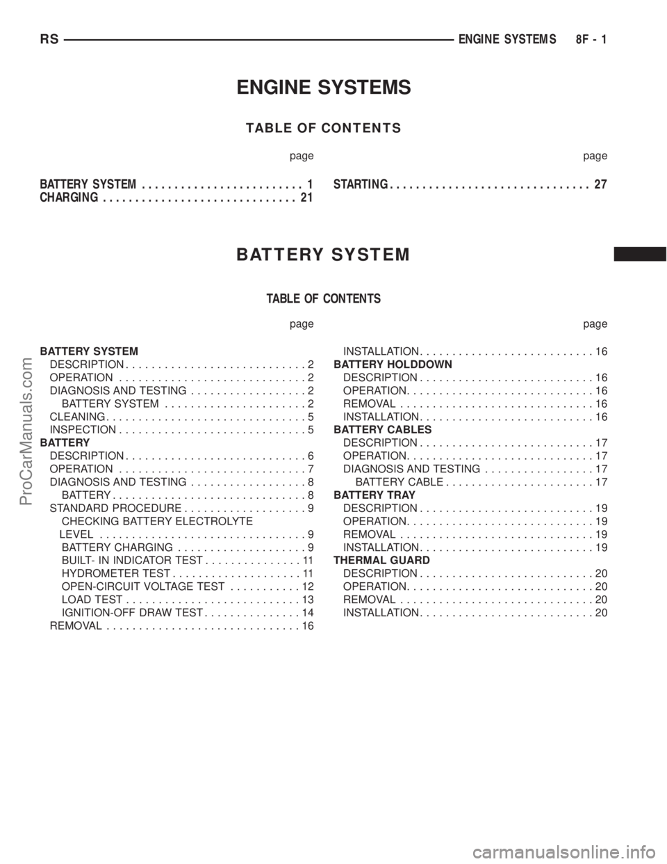
ENGINE SYSTEMS
TABLE OF CONTENTS
page page
BATTERY SYSTEM......................... 1
CHARGING.............................. 21STARTING............................... 27
BATTERY SYSTEM
TABLE OF CONTENTS
page page
BATTERY SYSTEM
DESCRIPTION............................2
OPERATION.............................2
DIAGNOSIS AND TESTING..................2
BATTERY SYSTEM......................2
CLEANING...............................5
INSPECTION.............................5
BATTERY
DESCRIPTION............................6
OPERATION.............................7
DIAGNOSIS AND TESTING..................8
BATTERY..............................8
STANDARD PROCEDURE...................9
CHECKING BATTERY ELECTROLYTE
LEVEL................................9
BATTERY CHARGING....................9
BUILT- IN INDICATOR TEST...............11
HYDROMETER TEST....................11
OPEN-CIRCUIT VOLTAGE TEST...........12
LOAD TEST...........................13
IGNITION-OFF DRAW TEST...............14
REMOVAL..............................16INSTALLATION...........................16
BATTERY HOLDDOWN
DESCRIPTION...........................16
OPERATION.............................16
REMOVAL..............................16
INSTALLATION...........................16
BATTERY CABLES
DESCRIPTION...........................17
OPERATION.............................17
DIAGNOSIS AND TESTING.................17
BATTERY CABLE.......................17
BATTERY TRAY
DESCRIPTION...........................19
OPERATION.............................19
REMOVAL..............................19
INSTALLATION...........................19
THERMAL GUARD
DESCRIPTION...........................20
OPERATION.............................20
REMOVAL..............................20
INSTALLATION...........................20
RSENGINE SYSTEMS8F-1
ProCarManuals.com
Page 390 of 2321
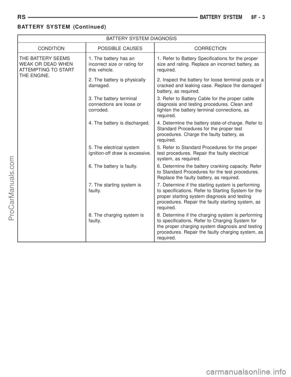
BATTERY SYSTEM DIAGNOSIS
CONDITION POSSIBLE CAUSES CORRECTION
THE BATTERY SEEMS
WEAK OR DEAD WHEN
ATTEMPTING TO START
THE ENGINE.1. The battery has an
incorrect size or rating for
this vehicle.1. Refer to Battery Specifications for the proper
size and rating. Replace an incorrect battery, as
required.
2. The battery is physically
damaged.2. Inspect the battery for loose terminal posts or a
cracked and leaking case. Replace the damaged
battery, as required.
3. The battery terminal
connections are loose or
corroded.3. Refer to Battery Cable for the proper cable
diagnosis and testing procedures. Clean and
tighten the battery terminal connections, as
required.
4. The battery is discharged. 4. Determine the battery state-of-charge. Refer to
Standard Procedures for the proper test
procedures. Charge the faulty battery, as
required.
5. The electrical system
ignition-off draw is excessive.5. Refer to Standard Procedures for the proper
test procedures. Repair the faulty electrical
system, as required.
6. The battery is faulty. 6. Determine the battery cranking capacity. Refer
to Standard Procedures for the test procedures.
Replace the faulty battery, as required.
7. The starting system is
faulty.7. Determine if the starting system is performing
to specifications. Refer to Starting System for the
proper starting system diagnosis and testing
procedures. Repair the faulty starting system, as
required.
8. The charging system is
faulty.8. Determine if the charging system is performing
to specifications. Refer to Charging System for
the proper charging system diagnosis and testing
procedures. Repair the faulty charging system, as
required.
RSBATTERY SYSTEM8F-3
BATTERY SYSTEM (Continued)
ProCarManuals.com
Page 391 of 2321
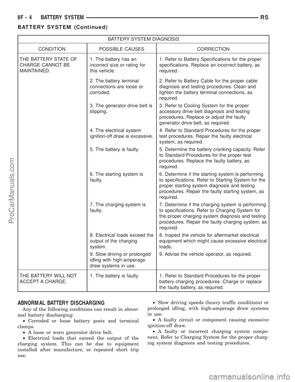
BATTERY SYSTEM DIAGNOSIS
CONDITION POSSIBLE CAUSES CORRECTION
THE BATTERY STATE OF
CHARGE CANNOT BE
MAINTAINED.1. The battery has an
incorrect size or rating for
this vehicle.1. Refer to Battery Specifications for the proper
specifications. Replace an incorrect battery, as
required.
2. The battery terminal
connections are loose or
corroded.2. Refer to Battery Cable for the proper cable
diagnosis and testing procedures. Clean and
tighten the battery terminal connections, as
required.
3. The generator drive belt is
slipping.3. Refer to Cooling System for the proper
accessory drive belt diagnosis and testing
procedures. Replace or adjust the faulty
generator drive belt, as required.
4. The electrical system
ignition-off draw is excessive.4. Refer to Standard Procedures for the proper
test procedures. Repair the faulty electrical
system, as required.
5. The battery is faulty. 5. Determine the battery cranking capacity. Refer
to Standard Procedures for the proper test
procedures. Replace the faulty battery, as
required.
6. The starting system is
faulty.6. Determine if the starting system is performing
to specifications. Refer to Starting System for the
proper starting system diagnosis and testing
procedures. Repair the faulty starting system, as
required.
7. The charging system is
faulty.7. Determine if the charging system is performing
to specifications. Refer to Charging System for
the proper charging system diagnosis and testing
procedures. Repair the faulty charging system, as
required.
8. Electrical loads exceed the
output of the charging
system.8. Inspect the vehicle for aftermarket electrical
equipment which might cause excessive electrical
loads.
9. Slow driving or prolonged
idling with high-amperage
draw systems in use.9. Advise the vehicle operator, as required.
THE BATTERY WILL NOT
ACCEPT A CHARGE.1. The battery is faulty. 1. Refer to Standard Procedures for the proper
battery charging procedures. Charge or replace
the faulty battery, as required.
ABNORMAL BATTERY DISCHARGING
Any of the following conditions can result in abnor-
mal battery discharging:
²Corroded or loose battery posts and terminal
clamps.
²A loose or worn generator drive belt.
²Electrical loads that exceed the output of the
charging system. This can be due to equipment
installed after manufacture, or repeated short trip
use.²Slow driving speeds (heavy traffic conditions) or
prolonged idling, with high-amperage draw systems
in use.
²A faulty circuit or component causing excessive
ignition-off draw.
²A faulty or incorrect charging system compo-
nent. Refer to Charging System for the proper charg-
ing system diagnosis and testing procedures.
8F - 4 BATTERY SYSTEMRS
BATTERY SYSTEM (Continued)
ProCarManuals.com
Page 401 of 2321
(4) Allow the battery to stabilize to open-circuit
voltage. It may take up to five minutes for the bat-
tery voltage to stabilize.
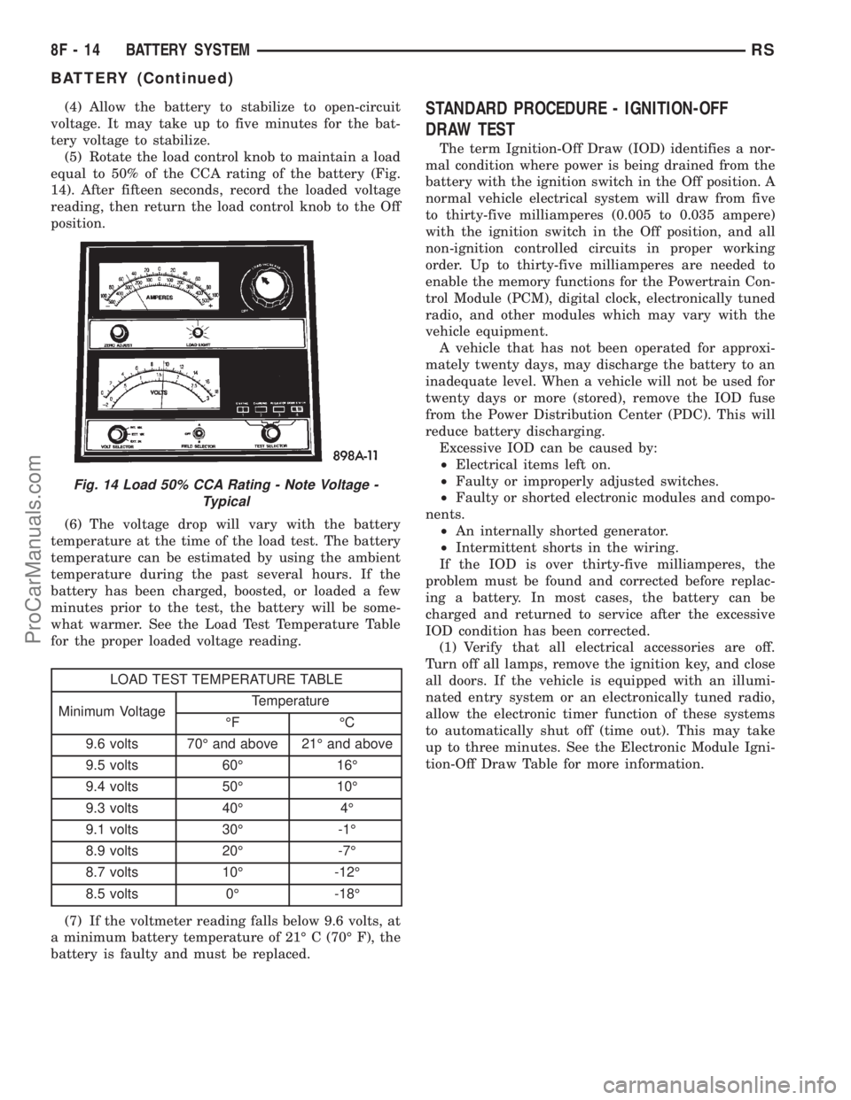
(5) Rotate the load control knob to maintain a load
equal to 50% of the CCA rating of the battery (Fig.
14). After fifteen seconds, record the loaded voltage
reading, then return the load control knob to the Off
position.
(6) The voltage drop will vary with the battery
temperature at the time of the load test. The battery
temperature can be estimated by using the ambient
temperature during the past several hours. If the
battery has been charged, boosted, or loaded a few
minutes prior to the test, the battery will be some-
what warmer. See the Load Test Temperature Table
for the proper loaded voltage reading.
LOAD TEST TEMPERATURE TABLE
Minimum VoltageTemperature
ÉF ÉC
9.6 volts 70É and above 21É and above
9.5 volts 60É 16É
9.4 volts 50É 10É
9.3 volts 40É 4É
9.1 volts 30É -1É
8.9 volts 20É -7É
8.7 volts 10É -12É
8.5 volts 0É -18É
(7) If the voltmeter reading falls below 9.6 volts, at
a minimum battery temperature of 21É C (70É F), the
battery is faulty and must be replaced.
STANDARD PROCEDURE - IGNITION-OFF
DRAW TEST
The term Ignition-Off Draw (IOD) identifies a nor-
mal condition where power is being drained from the
battery with the ignition switch in the Off position. A
normal vehicle electrical system will draw from five
to thirty-five milliamperes (0.005 to 0.035 ampere)
with the ignition switch in the Off position, and all
non-ignition controlled circuits in proper working
order. Up to thirty-five milliamperes are needed to
enable the memory functions for the Powertrain Con-
trol Module (PCM), digital clock, electronically tuned
radio, and other modules which may vary with the
vehicle equipment.
A vehicle that has not been operated for approxi-
mately twenty days, may discharge the battery to an
inadequate level. When a vehicle will not be used for
twenty days or more (stored), remove the IOD fuse
from the Power Distribution Center (PDC). This will
reduce battery discharging.
Excessive IOD can be caused by:
²Electrical items left on.
²Faulty or improperly adjusted switches.
²Faulty or shorted electronic modules and compo-
nents.
²An internally shorted generator.
²Intermittent shorts in the wiring.
If the IOD is over thirty-five milliamperes, the
problem must be found and corrected before replac-
ing a battery. In most cases, the battery can be
charged and returned to service after the excessive
IOD condition has been corrected.
(1) Verify that all electrical accessories are off.
Turn off all lamps, remove the ignition key, and close
all doors. If the vehicle is equipped with an illumi-
nated entry system or an electronically tuned radio,
allow the electronic timer function of these systems
to automatically shut off (time out). This may take
up to three minutes. See the Electronic Module Igni-
tion-Off Draw Table for more information.
Fig. 14 Load 50% CCA Rating - Note Voltage -
Typical
8F - 14 BATTERY SYSTEMRS
BATTERY (Continued)
ProCarManuals.com
Page 402 of 2321
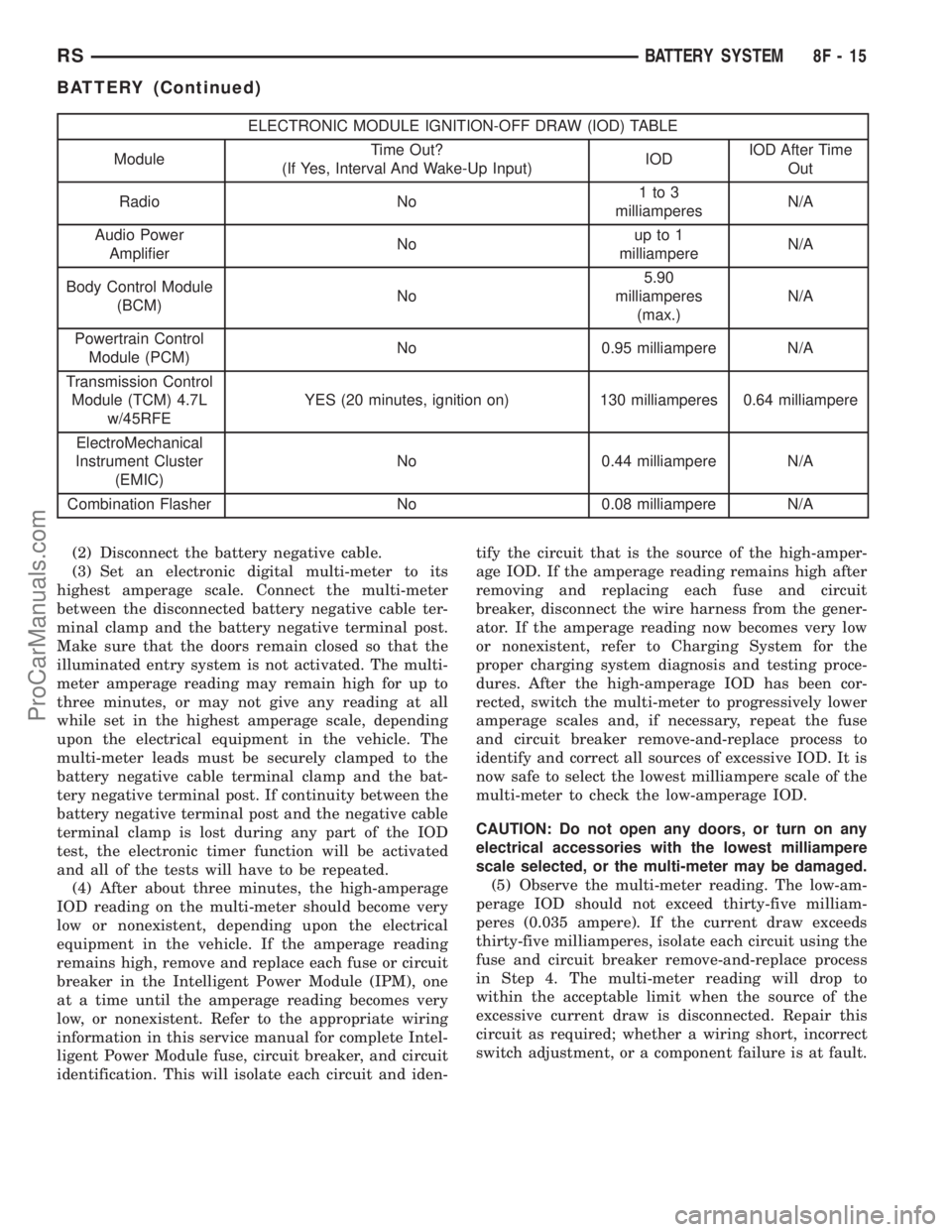
ELECTRONIC MODULE IGNITION-OFF DRAW (IOD) TABLE
ModuleTime Out?
(If Yes, Interval And Wake-Up Input)IODIOD After Time
Out
Radio No1to3
milliamperesN/A
Audio Power
AmplifierNoup to 1
milliampereN/A
Body Control Module
(BCM)No5.90
milliamperes
(max.)N/A
Powertrain Control
Module (PCM)No 0.95 milliampere N/A
Transmission Control
Module (TCM) 4.7L
w/45RFEYES (20 minutes, ignition on) 130 milliamperes 0.64 milliampere
ElectroMechanical
Instrument Cluster
(EMIC)No 0.44 milliampere N/A
Combination Flasher No 0.08 milliampere N/A
(2) Disconnect the battery negative cable.
(3) Set an electronic digital multi-meter to its
highest amperage scale. Connect the multi-meter
between the disconnected battery negative cable ter-
minal clamp and the battery negative terminal post.
Make sure that the doors remain closed so that the
illuminated entry system is not activated. The multi-
meter amperage reading may remain high for up to
three minutes, or may not give any reading at all
while set in the highest amperage scale, depending
upon the electrical equipment in the vehicle. The
multi-meter leads must be securely clamped to the
battery negative cable terminal clamp and the bat-
tery negative terminal post. If continuity between the
battery negative terminal post and the negative cable
terminal clamp is lost during any part of the IOD
test, the electronic timer function will be activated
and all of the tests will have to be repeated.
(4) After about three minutes, the high-amperage
IOD reading on the multi-meter should become very
low or nonexistent, depending upon the electrical
equipment in the vehicle. If the amperage reading
remains high, remove and replace each fuse or circuit
breaker in the Intelligent Power Module (IPM), one
at a time until the amperage reading becomes very
low, or nonexistent. Refer to the appropriate wiring
information in this service manual for complete Intel-
ligent Power Module fuse, circuit breaker, and circuit
identification. This will isolate each circuit and iden-tify the circuit that is the source of the high-amper-
age IOD. If the amperage reading remains high after
removing and replacing each fuse and circuit
breaker, disconnect the wire harness from the gener-
ator. If the amperage reading now becomes very low
or nonexistent, refer to Charging System for the
proper charging system diagnosis and testing proce-
dures. After the high-amperage IOD has been cor-
rected, switch the multi-meter to progressively lower
amperage scales and, if necessary, repeat the fuse
and circuit breaker remove-and-replace process to
identify and correct all sources of excessive IOD. It is
now safe to select the lowest milliampere scale of the
multi-meter to check the low-amperage IOD.
CAUTION: Do not open any doors, or turn on any
electrical accessories with the lowest milliampere
scale selected, or the multi-meter may be damaged.
(5) Observe the multi-meter reading. The low-am-
perage IOD should not exceed thirty-five milliam-
peres (0.035 ampere). If the current draw exceeds
thirty-five milliamperes, isolate each circuit using the
fuse and circuit breaker remove-and-replace process
in Step 4. The multi-meter reading will drop to
within the acceptable limit when the source of the
excessive current draw is disconnected. Repair this
circuit as required; whether a wiring short, incorrect
switch adjustment, or a component failure is at fault.
RSBATTERY SYSTEM8F-15
BATTERY (Continued)
ProCarManuals.com
Page 403 of 2321
REMOVAL - BATTERY
WARNING: A SUITABLE PAIR OF HEAVY DUTY
RUBBER GLOVES SHOULD BE WORN WHEN
REMOVING OR SERVICING A BATTERY.
WARNING: SAFETY GLASSES SHOULD BE WORN
WHEN REMOVING OR SERVICING A BATTERY.
WARNING: REMOVE METALLIC JEWELRY TO
AVOID INJURY BY ACCIDENTAL ARCING OF BAT-
TERY CURRENT.
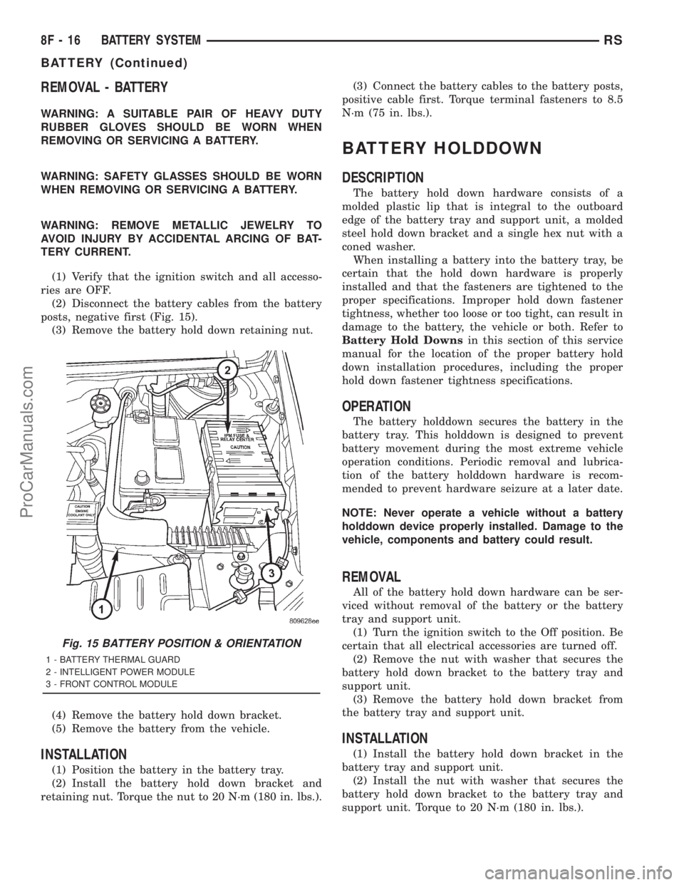
(1) Verify that the ignition switch and all accesso-
ries are OFF.
(2) Disconnect the battery cables from the battery
posts, negative first (Fig. 15).
(3) Remove the battery hold down retaining nut.
(4) Remove the battery hold down bracket.
(5) Remove the battery from the vehicle.
INSTALLATION
(1) Position the battery in the battery tray.
(2) Install the battery hold down bracket and
retaining nut. Torque the nut to 20 N´m (180 in. lbs.).(3) Connect the battery cables to the battery posts,
positive cable first. Torque terminal fasteners to 8.5
N´m (75 in. lbs.).
BATTERY HOLDDOWN
DESCRIPTION
The battery hold down hardware consists of a
molded plastic lip that is integral to the outboard
edge of the battery tray and support unit, a molded
steel hold down bracket and a single hex nut with a
coned washer.
When installing a battery into the battery tray, be
certain that the hold down hardware is properly
installed and that the fasteners are tightened to the
proper specifications. Improper hold down fastener
tightness, whether too loose or too tight, can result in
damage to the battery, the vehicle or both. Refer to
Battery Hold Downsin this section of this service
manual for the location of the proper battery hold
down installation procedures, including the proper
hold down fastener tightness specifications.
OPERATION
The battery holddown secures the battery in the
battery tray. This holddown is designed to prevent
battery movement during the most extreme vehicle
operation conditions. Periodic removal and lubrica-
tion of the battery holddown hardware is recom-
mended to prevent hardware seizure at a later date.
NOTE: Never operate a vehicle without a battery
holddown device properly installed. Damage to the
vehicle, components and battery could result.
REMOVAL
All of the battery hold down hardware can be ser-
viced without removal of the battery or the battery
tray and support unit.
(1) Turn the ignition switch to the Off position. Be
certain that all electrical accessories are turned off.
(2) Remove the nut with washer that secures the
battery hold down bracket to the battery tray and
support unit.
(3) Remove the battery hold down bracket from
the battery tray and support unit.
INSTALLATION
(1) Install the battery hold down bracket in the
battery tray and support unit.
(2) Install the nut with washer that secures the
battery hold down bracket to the battery tray and
support unit. Torque to 20 N´m (180 in. lbs.).
Fig. 15 BATTERY POSITION & ORIENTATION
1 - BATTERY THERMAL GUARD
2 - INTELLIGENT POWER MODULE
3 - FRONT CONTROL MODULE
8F - 16 BATTERY SYSTEMRS
BATTERY (Continued)
ProCarManuals.com