2001 DODGE TOWN AND COUNTRY checking oil
[x] Cancel search: checking oilPage 1290 of 2321
Run engine until achieving normal operating tem-
perature.
(1) Position the vehicle on a level surface and turn
engine off.
(2) Hoist and support vehicle on safety stands.
Refer to Hoisting and Jacking Recommendations.
(Refer to LUBRICATION & MAINTENANCE/HOIST-
ING - STANDARD PROCEDURE)
(3) Remove oil fill cap.
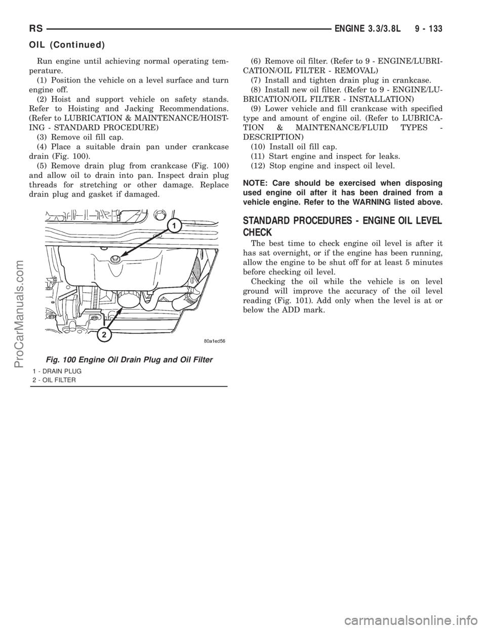
(4) Place a suitable drain pan under crankcase
drain (Fig. 100).
(5) Remove drain plug from crankcase (Fig. 100)
and allow oil to drain into pan. Inspect drain plug
threads for stretching or other damage. Replace
drain plug and gasket if damaged.(6) Remove oil filter. (Refer to 9 - ENGINE/LUBRI-
CATION/OIL FILTER - REMOVAL)
(7) Install and tighten drain plug in crankcase.
(8) Install new oil filter. (Refer to 9 - ENGINE/LU-
BRICATION/OIL FILTER - INSTALLATION)
(9) Lower vehicle and fill crankcase with specified
type and amount of engine oil. (Refer to LUBRICA-
TION & MAINTENANCE/FLUID TYPES -
DESCRIPTION)
(10) Install oil fill cap.
(11) Start engine and inspect for leaks.
(12) Stop engine and inspect oil level.
NOTE: Care should be exercised when disposing
used engine oil after it has been drained from a
vehicle engine. Refer to the WARNING listed above.
STANDARD PROCEDURES - ENGINE OIL LEVEL
CHECK
The best time to check engine oil level is after it
has sat overnight, or if the engine has been running,
allow the engine to be shut off for at least 5 minutes
before checking oil level.
Checking the oil while the vehicle is on level
ground will improve the accuracy of the oil level
reading (Fig. 101). Add only when the level is at or
below the ADD mark.
Fig. 100 Engine Oil Drain Plug and Oil Filter
1 - DRAIN PLUG
2 - OIL FILTER
RSENGINE 3.3/3.8L9 - 133
OIL (Continued)
ProCarManuals.com
Page 1296 of 2321
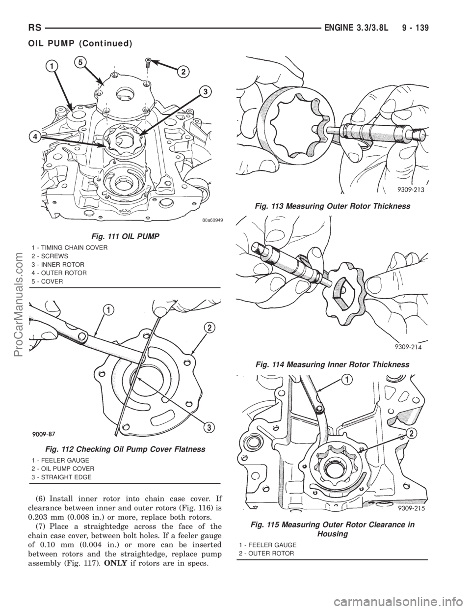
(6) Install inner rotor into chain case cover. If
clearance between inner and outer rotors (Fig. 116) is
0.203 mm (0.008 in.) or more, replace both rotors.
(7) Place a straightedge across the face of the
chain case cover, between bolt holes. If a feeler gauge
of 0.10 mm (0.004 in.) or more can be inserted
between rotors and the straightedge, replace pump
assembly (Fig. 117).ONLYif rotors are in specs.
Fig. 111 OIL PUMP
1 - TIMING CHAIN COVER
2 - SCREWS
3 - INNER ROTOR
4 - OUTER ROTOR
5 - COVER
Fig. 112 Checking Oil Pump Cover Flatness
1 - FEELER GAUGE
2 - OIL PUMP COVER
3 - STRAIGHT EDGE
Fig. 113 Measuring Outer Rotor Thickness
Fig. 114 Measuring Inner Rotor Thickness
Fig. 115 Measuring Outer Rotor Clearance in
Housing
1 - FEELER GAUGE
2 - OUTER ROTOR
RSENGINE 3.3/3.8L9 - 139
OIL PUMP (Continued)
ProCarManuals.com
Page 1316 of 2321
ENGINE 2.5L TURBO DIESEL
TABLE OF CONTENTS
page page
ENGINE 2.5L TURBO DIESEL
DESCRIPTION............................2
REMOVAL...............................3
INSTALLATION............................6
SPECIFICATIONS.........................7
SPECIAL TOOLS.........................12
CYLINDER HEAD
STANDARD PROCEDURE..................18
VALVE SERVICE.......................18
MEASURING PISTON PROTRUSION........19
REMOVAL..............................20
CLEANING..............................21
INSPECTION............................22
INSTALLATION...........................22
CAMSHAFT(S)
DESCRIPTION...........................23
OPERATION.............................23
REMOVAL..............................23
INSTALLATION...........................24
CYLINDER HEAD COVER(S)
DESCRIPTION...........................24
REMOVAL..............................24
INSTALLATION...........................26
CAMSHAFT OIL SEAL(S)
REMOVAL..............................28
INSTALLATION...........................28
ROCKER ARMS
DESCRIPTION...........................28
OPERATION.............................28
REMOVAL..............................28
INSTALLATION...........................29
HYDRAULIC LIFTERS
DESCRIPTION...........................30
REMOVAL..............................30
INSPECTION............................31
INSTALLATION...........................31
ENGINE BLOCK
DESCRIPTION...........................31
CRANKSHAFT
DESCRIPTION...........................31
OPERATION.............................31
STANDARD PROCEDURE..................32
CHECKING CRANKSHAFT END PLAY.......32
REMOVAL..............................32
INSTALLATION...........................33
CYLINDER LINERS
DESCRIPTION...........................34
REMOVAL..............................34
INSPECTION............................34INSTALLATION...........................35
INTERNAL VACUUM PUMP
DESCRIPTION...........................36
REMOVAL..............................36
INSTALLATION...........................36
PISTON & CONNECTING ROD
DESCRIPTION...........................37
STANDARD PROCEDURE..................37
PISTON RING FITTING..................37
REMOVAL..............................38
INSPECTION............................38
INSTALLATION...........................40
CRANKSHAFT OIL SEAL - FRONT
REMOVAL..............................42
INSTALLATION...........................42
VIBRATION DAMPER
REMOVAL..............................43
INSTALLATION...........................44
ENGINE COVER - FRONT
DESCRIPTION...........................44
REMOVAL..............................44
INSTALLATION...........................45
CRANKSHAFT MAIN BEARINGS
REMOVAL..............................45
INSTALLATION...........................46
CRANKSHAFT OIL SEAL - REAR
REMOVAL..............................46
INSTALLATION...........................46
OIL PAN
REMOVAL..............................46
INSTALLATION...........................47
OIL PUMP
REMOVAL..............................47
INSTALLATION...........................48
OIL PRESSURE SENSOR/SWITCH
DESCRIPTION...........................49
REMOVAL..............................49
INSTALLATION...........................50
OIL TEMPERATURE SENSOR
DESCRIPTION...........................50
REMOVAL..............................50
INSTALLATION...........................50
OIL PRESSURE RELIEF VALVE
DESCRIPTION...........................50
REMOVAL..............................51
INSTALLATION...........................51
OIL COOLER & LINES
REMOVAL..............................51
INSTALLATION...........................52
RGENGINE 2.5L TURBO DIESEL9a-1
ProCarManuals.com
Page 1347 of 2321
STANDARD PROCEDURE - CHECKING
CRANKSHAFT END PLAY
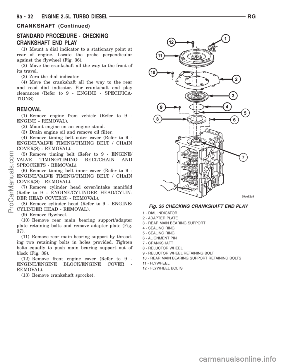
(1) Mount a dial indicator to a stationary point at
rear of engine. Locate the probe perpendicular
against the flywheel (Fig. 36).
(2) Move the crankshaft all the way to the front of
its travel.
(3) Zero the dial indicator.
(4) Move the crankshaft all the way to the rear
and read dial indicator. For crankshaft end play
clearances (Refer to 9 - ENGINE - SPECIFICA-
TIONS).
REMOVAL
(1) Remove engine from vehicle (Refer to 9 -
ENGINE - REMOVAL).
(2) Mount engine on an engine stand.
(3) Drain engine oil and remove oil filter.
(4) Remove timing belt outer cover (Refer to 9 -
ENGINE/VALVE TIMING/TIMING BELT / CHAIN
COVER(S) - REMOVAL).
(5) Remove timing belt (Refer to 9 - ENGINE/
VALVE TIMING/TIMING BELT/CHAIN AND
SPROCKETS - REMOVAL).
(6) Remove timing belt inner cover (Refer to 9 -
ENGINE/VALVE TIMING/TIMING BELT / CHAIN
COVER(S) - REMOVAL).
(7) Remove cylinder head cover/intake manifold
(Refer to 9 - ENGINE/CYLINDER HEAD/CYLIN-
DER HEAD COVER(S) - REMOVAL).
(8) Remove cylinder head (Refer to 9 - ENGINE/
CYLINDER HEAD - REMOVAL).
(9) Remove flywheel.
(10) Remove rear main bearing support/adapter
plate retaining bolts and remove adapter plate (Fig.
37).
(11) Remove rear main bearing support by thread-
ing two retaining bolts in holes provided. Tighten
bolts equally to push main bearing support out of
block (Fig. 38).
(12) Remove front engine cover (Refer to 9 -
ENGINE/ENGINE BLOCK/ENGINE COVER -
REMOVAL).
(13) Remove crankshaft sprocket.
Fig. 36 CHECKING CRANKSHAFT END PLAY
1 - DIAL INDICATOR
2 - ADAPTER PLATE
3 - REAR MAIN BEARING SUPPORT
4 - SEALING RING
5 - SEALING RING
6 - ALIGNMENT PIN
7 - CRANKSHAFT
8 - RELUCTOR WHEEL
9 - RELUCTOR WHEEL RETAINING BOLT
10 - REAR MAIN BEARING SUPPORT RETAINING BOLTS
11 - FLYWHEEL
12 - FLYWHEEL BOLTS
9a - 32 ENGINE 2.5L TURBO DIESELRG
CRANKSHAFT (Continued)
ProCarManuals.com
Page 1594 of 2321
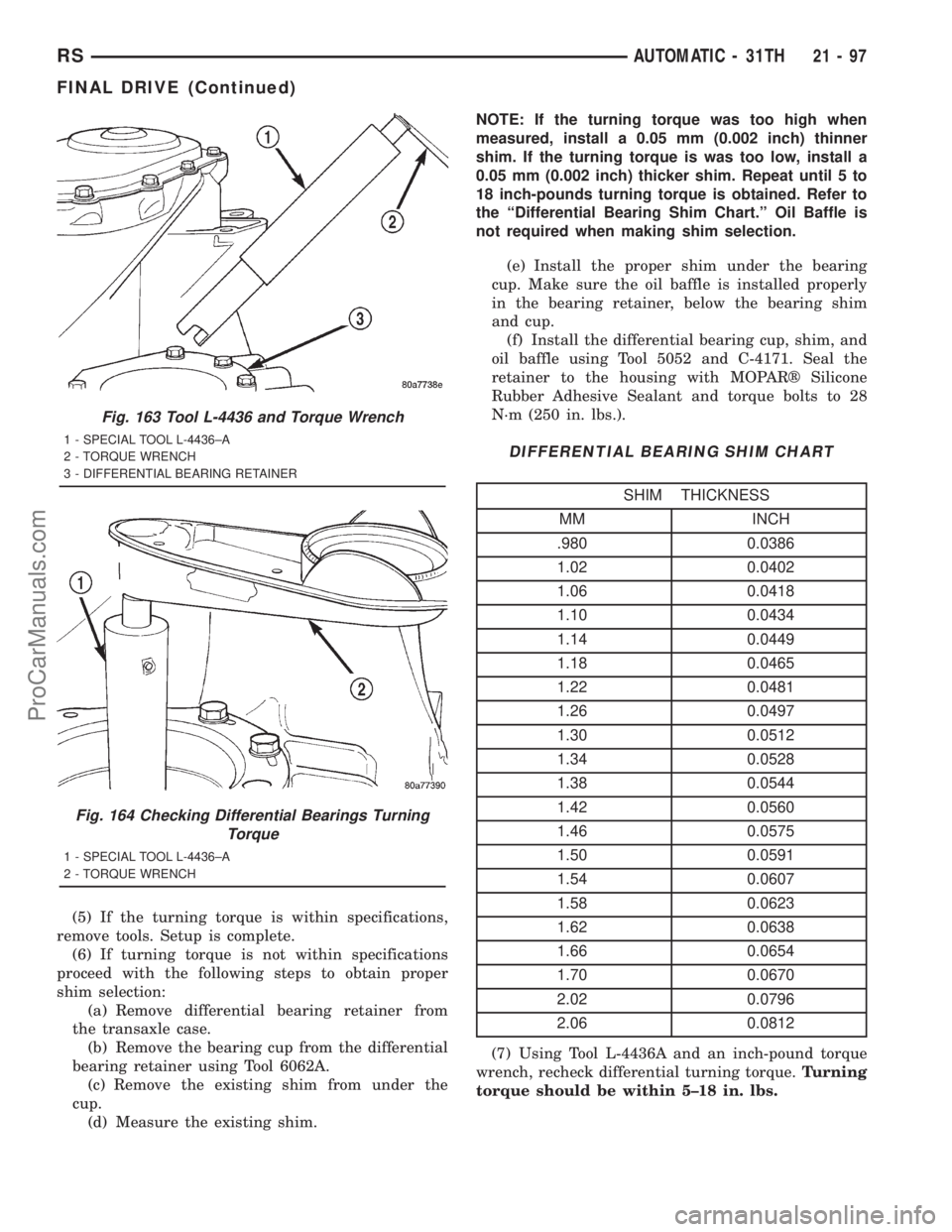
(5) If the turning torque is within specifications,
remove tools. Setup is complete.
(6) If turning torque is not within specifications
proceed with the following steps to obtain proper
shim selection:
(a) Remove differential bearing retainer from
the transaxle case.
(b) Remove the bearing cup from the differential
bearing retainer using Tool 6062A.
(c) Remove the existing shim from under the
cup.
(d) Measure the existing shim.NOTE: If the turning torque was too high when
measured, install a 0.05 mm (0.002 inch) thinner
shim. If the turning torque is was too low, install a
0.05 mm (0.002 inch) thicker shim. Repeat until 5 to
18 inch-pounds turning torque is obtained. Refer to
the ªDifferential Bearing Shim Chart.º Oil Baffle is
not required when making shim selection.
(e) Install the proper shim under the bearing
cup. Make sure the oil baffle is installed properly
in the bearing retainer, below the bearing shim
and cup.
(f) Install the differential bearing cup, shim, and
oil baffle using Tool 5052 and C-4171. Seal the
retainer to the housing with MOPARž Silicone
Rubber Adhesive Sealant and torque bolts to 28
N´m (250 in. lbs.).
DIFFERENTIAL BEARING SHIM CHART
SHIM THICKNESS
MM INCH
.980 0.0386
1.02 0.0402
1.06 0.0418
1.10 0.0434
1.14 0.0449
1.18 0.0465
1.22 0.0481
1.26 0.0497
1.30 0.0512
1.34 0.0528
1.38 0.0544
1.42 0.0560
1.46 0.0575
1.50 0.0591
1.54 0.0607
1.58 0.0623
1.62 0.0638
1.66 0.0654
1.70 0.0670
2.02 0.0796
2.06 0.0812
(7) Using Tool L-4436A and an inch-pound torque
wrench, recheck differential turning torque.Turning
torque should be within 5±18 in. lbs.
Fig. 163 Tool L-4436 and Torque Wrench
1 - SPECIAL TOOL L-4436±A
2 - TORQUE WRENCH
3 - DIFFERENTIAL BEARING RETAINER
Fig. 164 Checking Differential Bearings Turning
Torque
1 - SPECIAL TOOL L-4436±A
2 - TORQUE WRENCH
RSAUTOMATIC - 31TH21-97
FINAL DRIVE (Continued)
ProCarManuals.com
Page 1622 of 2321
TORQUE CONVERTER CLUTCH (TCC)
In a standard torque converter, the impeller and
turbine are rotating at about the same speed and the
stator is freewheeling, providing no torque multipli-
cation. By applying the turbine's piston to the front
cover's friction material, a total converter engage-
ment can be obtained. The result of this engagement
is a direct 1:1 mechanical link between the engine
and the transmission.
The engagement and disengagement of the TCC
are automatic and controlled by the Powertrain Con-
trol Module (PCM). The engagement cannot be acti-
vated in the lower gears because it eliminates the
torque multiplication effect of the torque converter
necessary for acceleration. Inputs that determine
clutch engagement are: coolant temperature, vehicle
speed and throttle position. The torque converter
clutch is engaged by the clutch solenoid on the valve
body. The clutch will engage at approximately 56
km/h (35 mph) with light throttle, after the shift to
third gear.
REMOVAL
(1) Remove transmission and torque converter
from vehicle. (Refer to 21 - TRANSMISSION/TRANS-
AXLE/AUTOMATIC - 31TH - REMOVAL)
(2) Place a suitable drain pan under the converter
housing end of the transmission.
CAUTION: Verify that transmission is secure on the
lifting device or work surface, the center of gravity
of the transmission will shift when the torque con-
verter is removed creating an unstable condition.
The torque converter is a heavy unit. Use caution
when separating the torque converter from the
transmission.
(3) Pull the torque converter forward until the cen-
ter hub clears the oil pump seal.
(4) Separate the torque converter from the trans-
mission.
INSTALLATION
Check converter hub and drive notches for sharp
edges, burrs, scratches, or nicks. Polish the hub and
notches with 320/400 grit paper or crocus cloth if nec-
essary. The hub must be smooth to avoid damaging
the pump seal at installation.(1) Lubricate converter hub and oil pump seal lip
with transmission fluid.
(2) Place torque converter in position on transmis-
sion.
CAUTION: Do not damage oil pump seal or bushing
while inserting torque converter into the front of the
transmission.
(3) Align torque converter to oil pump seal open-
ing.
(4) Insert torque converter hub into oil pump.
(5) While pushing torque converter inward, rotate
converter until converter is fully seated in the oil
pump gears.
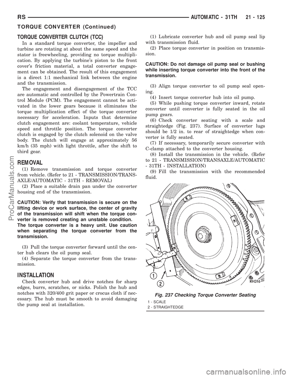
(6) Check converter seating with a scale and
straightedge (Fig. 237). Surface of converter lugs
should be 1/2 in. to rear of straightedge when con-
verter is fully seated.
(7) If necessary, temporarily secure converter with
C-clamp attached to the converter housing.
(8) Install the transmission in the vehicle. (Refer
to 21 - TRANSMISSION/TRANSAXLE/AUTOMATIC
- 31TH - INSTALLATION)
(9) Fill the transmission with the recommended
fluid.
Fig. 237 Checking Torque Converter Seating
1 - SCALE
2 - STRAIGHTEDGE
RSAUTOMATIC - 31TH21 - 125
TORQUE CONVERTER (Continued)
ProCarManuals.com
Page 1656 of 2321
VALVE BODY
DESCRIPTION..........................289
OPERATION............................290
REMOVAL.............................290DISASSEMBLY..........................292
ASSEMBLY............................296
INSTALLATION..........................301
AUTOMATIC - 41TE
TRANSAXLE IDENTIFICATION
DESCRIPTION
The 41TE (Fig. 1) is a four-speed transaxle that is
a conventional hydraulic/mechanical assembly with
an integral differential, and is controlled with adap-
tive electronic controls and monitors. The hydraulic
system of the transaxle consists of the transaxle
fluid, fluid passages, hydraulic valves, and various
line pressure control components. An input clutch
assembly which houses the underdrive, overdrive,
and reverse clutches is used. It also utilizes separate
holding clutches: 2nd/4th gear and Low/Reverse. The
primary mechanical components of the transaxle con-
sist of the following:
²Three multiple disc input clutches
²Two multiple disc holding clutches
²Four hydraulic accumulators
²Two planetary gear sets
²Hydraulic oil pump
²Valve body
²Solenoid/Pressure switch assembly
²Integral differential assembly
Control of the transaxle is accomplished by fully
adaptive electronics. Optimum shift scheduling is
accomplished through continuous real-time sensor
feedback information provided to the Transmission
Control Module (TCM).
The TCM is the heart of the electronic control sys-
tem and relies on information from various direct
and indirect inputs (sensors, switches, etc.) to deter-
mine driver demand and vehicle operating condi-
tions. With this information, the TCM can calculate
and perform timely and quality shifts through vari-
ous output or control devices (solenoid pack, trans-
mission control relay, etc.).
The TCM also performs certain self-diagnostic
functions and provides comprehensive information
(sensor data, DTC's, etc.) which is helpful in proper
diagnosis and repair. This information can be viewed
with the DRB scan tool.
The 41TE transaxle identification code is a series
of digits printed on a bar-code label that is fixed to
the transaxle case as shown in (Fig. 2).For example, the identification code K 821 1125
1316 can be broken down as follows:
²K = Kokomo Transmission Plant
²821 = Last three digits of the transaxle part
number
²1125 = Build date
²1316 = Build sequence number
If the tag is not legible or missing, the ªPKº num-
ber, which is stamped into the transaxle case behind
the transfer gear cover, can be referred to for identi-
fication. This number differs slightly in that it con-
tains the entire transaxle part number, rather than
the last three digits.
OPERATION
Transmission output is directed to an integral dif-
ferential by a transfer gear system in the following
input-to-output ratios:
First...............................2.84 : 1
Second.............................1.57 : 1
Third..............................1.00 : 1
Overdrive...........................0.69 : 1
Reverse............................2.21 : 1
DIAGNOSIS AND TESTING - 41TE TRANSAXLE
GENERAL DIAGNOSIS
NOTE: Before attempting any repair on a 41TE four-
speed automatic transaxle, check for diagnostic
trouble codes (DTC's) using the DRB scan tool.
Refer to the Transmission Diagnostic Procedures
Manual.
Transaxle malfunctions may be caused by these
general conditions:
²Poor engine performance
²Improper adjustments
²Hydraulic malfunctions
²Mechanical malfunctions
²Electronic malfunctions
Diagnosis of these problems should always begin
by checking the easily accessible variables: fluid level
and condition, gearshift cable adjustment. Then per-
form a road test to determine if the problem has been
corrected or that more diagnosis is necessary. If the
problem persists after the preliminary tests and cor-
rections are completed, hydraulic pressure checks
should be performed.
RSAUTOMATIC - 41TE21 - 159
ProCarManuals.com
Page 1741 of 2321
(6) If turning torque is not within specifications
proceed with the following steps.
(a) Remove differential bearing retainer from
the transaxle case.
(b) Remove the bearing cup from the differential
bearing retainer using Tool 6062A.
(c) Remove the existing shim from under the
cup.
(d) Measure the existing shim.
(e) If the turning torque was too high when mea-
sured, install a 0.05 mm (0.002 inch) thinner shim.
If the turning torque is was too low, install a 0.05
mm (0.002 inch) thicker shim. Repeat until 5-18
inch-pounds turning torque is obtained. Oil Baffle
is not required to be installed when making shim
selection.
(f) Install the proper shim under the bearing
cup. Make sure the oil baffle is installed properly
in the bearing retainer, below the bearing shim
and cup.
(g) Install the differential bearing retainer using
Tool 5052 and C-4171. Seal the retainer to the
housing with MOPARž Silicone Rubber Adhesive
Sealant and torque bolts to 28 N´m (250 in. lbs.).
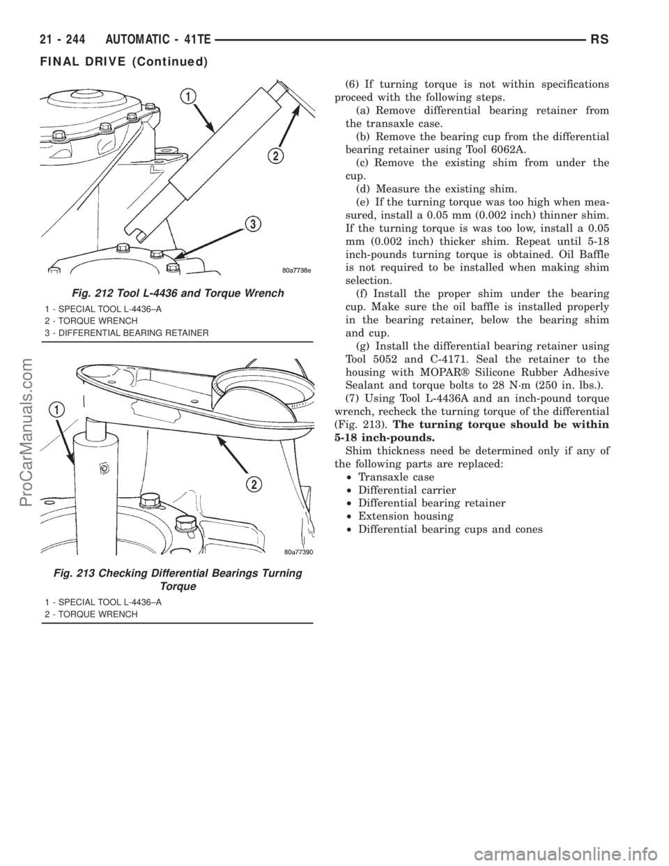
(7) Using Tool L-4436A and an inch-pound torque
wrench, recheck the turning torque of the differential
(Fig. 213).The turning torque should be within
5-18 inch-pounds.
Shim thickness need be determined only if any of
the following parts are replaced:
²Transaxle case
²Differential carrier
²Differential bearing retainer
²Extension housing
²Differential bearing cups and cones
Fig. 212 Tool L-4436 and Torque Wrench
1 - SPECIAL TOOL L-4436±A
2 - TORQUE WRENCH
3 - DIFFERENTIAL BEARING RETAINER
Fig. 213 Checking Differential Bearings Turning
Torque
1 - SPECIAL TOOL L-4436±A
2 - TORQUE WRENCH
21 - 244 AUTOMATIC - 41TERS
FINAL DRIVE (Continued)
ProCarManuals.com