2001 DODGE TOWN AND COUNTRY stop start
[x] Cancel search: stop startPage 1290 of 2321
Run engine until achieving normal operating tem-
perature.
(1) Position the vehicle on a level surface and turn
engine off.
(2) Hoist and support vehicle on safety stands.
Refer to Hoisting and Jacking Recommendations.
(Refer to LUBRICATION & MAINTENANCE/HOIST-
ING - STANDARD PROCEDURE)
(3) Remove oil fill cap.
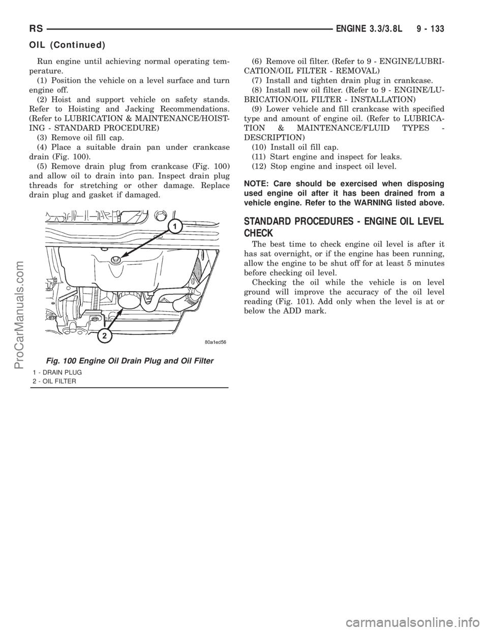
(4) Place a suitable drain pan under crankcase
drain (Fig. 100).
(5) Remove drain plug from crankcase (Fig. 100)
and allow oil to drain into pan. Inspect drain plug
threads for stretching or other damage. Replace
drain plug and gasket if damaged.(6) Remove oil filter. (Refer to 9 - ENGINE/LUBRI-
CATION/OIL FILTER - REMOVAL)
(7) Install and tighten drain plug in crankcase.
(8) Install new oil filter. (Refer to 9 - ENGINE/LU-
BRICATION/OIL FILTER - INSTALLATION)
(9) Lower vehicle and fill crankcase with specified
type and amount of engine oil. (Refer to LUBRICA-
TION & MAINTENANCE/FLUID TYPES -
DESCRIPTION)
(10) Install oil fill cap.
(11) Start engine and inspect for leaks.
(12) Stop engine and inspect oil level.
NOTE: Care should be exercised when disposing
used engine oil after it has been drained from a
vehicle engine. Refer to the WARNING listed above.
STANDARD PROCEDURES - ENGINE OIL LEVEL
CHECK
The best time to check engine oil level is after it
has sat overnight, or if the engine has been running,
allow the engine to be shut off for at least 5 minutes
before checking oil level.
Checking the oil while the vehicle is on level
ground will improve the accuracy of the oil level
reading (Fig. 101). Add only when the level is at or
below the ADD mark.
Fig. 100 Engine Oil Drain Plug and Oil Filter
1 - DRAIN PLUG
2 - OIL FILTER
RSENGINE 3.3/3.8L9 - 133
OIL (Continued)
ProCarManuals.com
Page 1390 of 2321
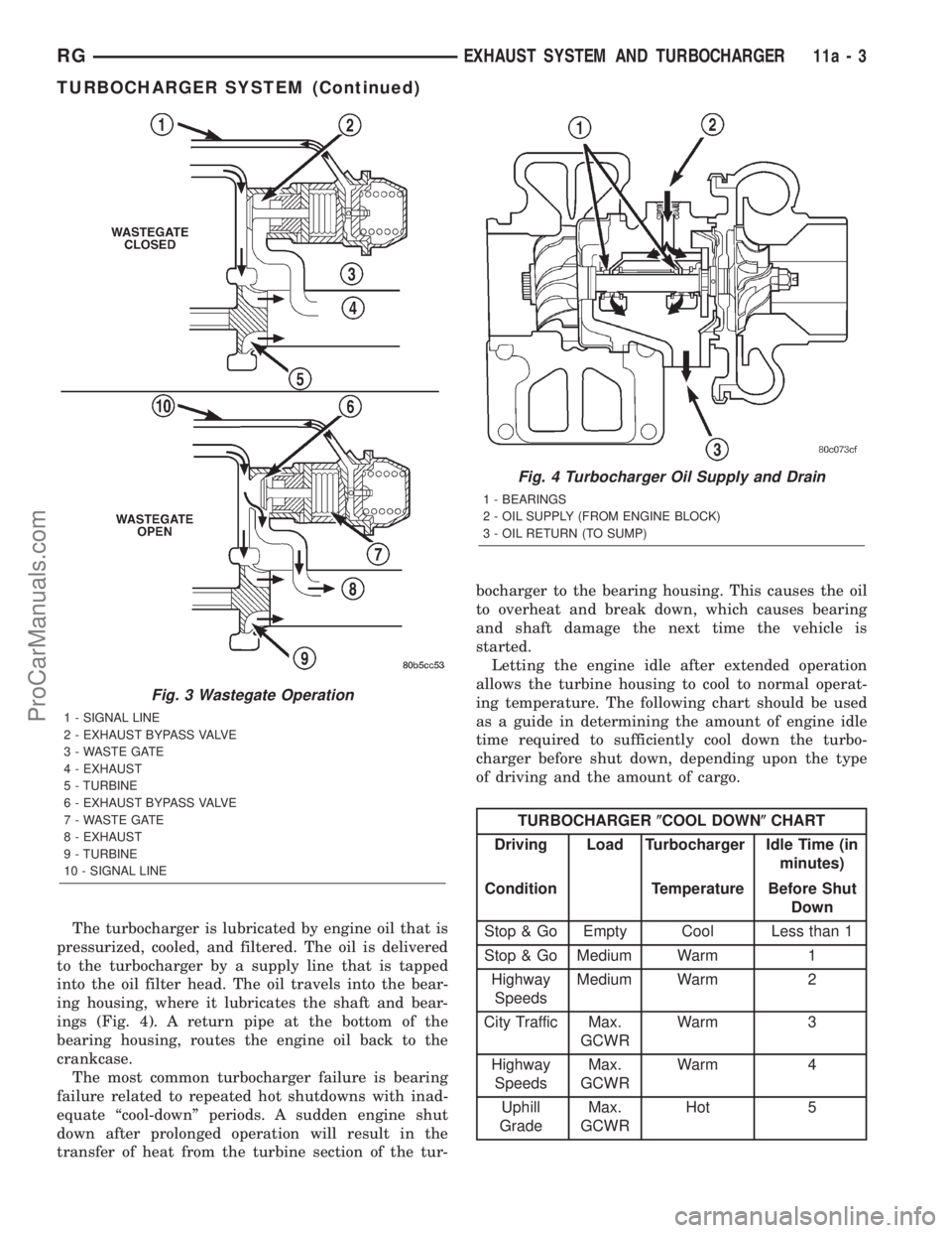
The turbocharger is lubricated by engine oil that is
pressurized, cooled, and filtered. The oil is delivered
to the turbocharger by a supply line that is tapped
into the oil filter head. The oil travels into the bear-
ing housing, where it lubricates the shaft and bear-
ings (Fig. 4). A return pipe at the bottom of the
bearing housing, routes the engine oil back to the
crankcase.
The most common turbocharger failure is bearing
failure related to repeated hot shutdowns with inad-
equate ªcool-downº periods. A sudden engine shut
down after prolonged operation will result in the
transfer of heat from the turbine section of the tur-bocharger to the bearing housing. This causes the oil
to overheat and break down, which causes bearing
and shaft damage the next time the vehicle is
started.
Letting the engine idle after extended operation
allows the turbine housing to cool to normal operat-
ing temperature. The following chart should be used
as a guide in determining the amount of engine idle
time required to sufficiently cool down the turbo-
charger before shut down, depending upon the type
of driving and the amount of cargo.
TURBOCHARGER(COOL DOWN(CHART
Driving Load Turbocharger Idle Time (in
minutes)
Condition Temperature Before Shut
Down
Stop & Go Empty Cool Less than 1
Stop & Go Medium Warm 1
Highway
SpeedsMedium Warm 2
City Traffic Max.
GCWRWarm 3
Highway
SpeedsMax.
GCWRWarm 4
Uphill
GradeMax.
GCWRHot 5
Fig. 3 Wastegate Operation
1 - SIGNAL LINE
2 - EXHAUST BYPASS VALVE
3 - WASTE GATE
4 - EXHAUST
5 - TURBINE
6 - EXHAUST BYPASS VALVE
7 - WASTE GATE
8 - EXHAUST
9 - TURBINE
10 - SIGNAL LINE
Fig. 4 Turbocharger Oil Supply and Drain
1 - BEARINGS
2 - OIL SUPPLY (FROM ENGINE BLOCK)
3 - OIL RETURN (TO SUMP)
RGEXHAUST SYSTEM AND TURBOCHARGER11a-3
TURBOCHARGER SYSTEM (Continued)
ProCarManuals.com
Page 1452 of 2321
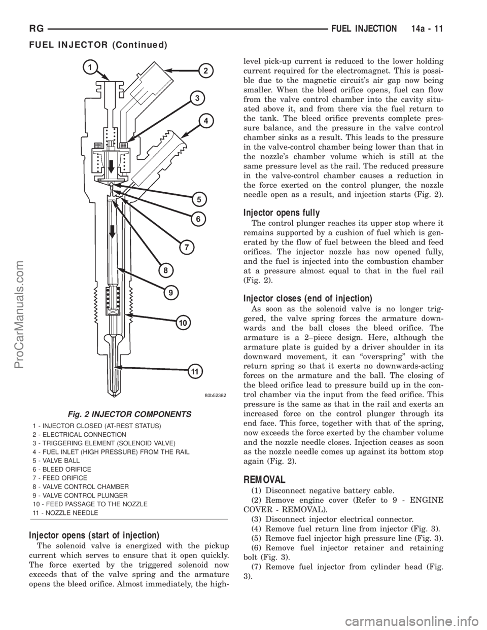
Injector opens (start of injection)
The solenoid valve is energized with the pickup
current which serves to ensure that it open quickly.
The force exerted by the triggered solenoid now
exceeds that of the valve spring and the armature
opens the bleed orifice. Almost immediately, the high-level pick-up current is reduced to the lower holding
current required for the electromagnet. This is possi-
ble due to the magnetic circuit's air gap now being
smaller. When the bleed orifice opens, fuel can flow
from the valve control chamber into the cavity situ-
ated above it, and from there via the fuel return to
the tank. The bleed orifice prevents complete pres-
sure balance, and the pressure in the valve control
chamber sinks as a result. This leads to the pressure
in the valve-control chamber being lower than that in
the nozzle's chamber volume which is still at the
same pressure level as the rail. The reduced pressure
in the valve-control chamber causes a reduction in
the force exerted on the control plunger, the nozzle
needle open as a result, and injection starts (Fig. 2).
Injector opens fully
The control plunger reaches its upper stop where it
remains supported by a cushion of fuel which is gen-
erated by the flow of fuel between the bleed and feed
orifices. The injector nozzle has now opened fully,
and the fuel is injected into the combustion chamber
at a pressure almost equal to that in the fuel rail
(Fig. 2).
Injector closes (end of injection)
As soon as the solenoid valve is no longer trig-
gered, the valve spring forces the armature down-
wards and the ball closes the bleed orifice. The
armature is a 2±piece design. Here, although the
armature plate is guided by a driver shoulder in its
downward movement, it can ªoverspringº with the
return spring so that it exerts no downwards-acting
forces on the armature and the ball. The closing of
the bleed orifice lead to pressure build up in the con-
trol chamber via the input from the feed orifice. This
pressure is the same as that in the rail and exerts an
increased force on the control plunger through its
end face. This force, together with that of the spring,
now exceeds the force exerted by the chamber volume
and the nozzle needle closes. Injection ceases as soon
as the nozzle needle comes up against its bottom stop
again (Fig. 2).
REMOVAL
(1) Disconnect negative battery cable.
(2) Remove engine cover (Refer to 9 - ENGINE
COVER - REMOVAL).
(3) Disconnect injector electrical connector.
(4) Remove fuel return line from injector (Fig. 3).
(5) Remove fuel injector high pressure line (Fig. 3).
(6) Remove fuel injector retainer and retaining
bolt (Fig. 3).
(7) Remove fuel injector from cylinder head (Fig.
3).
Fig. 2 INJECTOR COMPONENTS
1 - INJECTOR CLOSED (AT-REST STATUS)
2 - ELECTRICAL CONNECTION
3 - TRIGGERING ELEMENT (SOLENOID VALVE)
4 - FUEL INLET (HIGH PRESSURE) FROM THE RAIL
5 - VALVE BALL
6 - BLEED ORIFICE
7 - FEED ORIFICE
8 - VALVE CONTROL CHAMBER
9 - VALVE CONTROL PLUNGER
10 - FEED PASSAGE TO THE NOZZLE
11 - NOZZLE NEEDLE
RGFUEL INJECTION14a-11
FUEL INJECTOR (Continued)
ProCarManuals.com
Page 1482 of 2321
SERVICE WARNINGS AND CAUTIONS
WARNING: POWER STEERING FLUID, ENGINE
PARTS AND EXHAUST SYSTEM MAY BE
EXTREMELY HOT IF ENGINE HAS BEEN RUNNING.
DO NOT START ENGINE WITH ANY LOOSE OR DIS-
CONNECTED HOSES. DO NOT ALLOW HOSES TO
TOUCH HOT EXHAUST MANIFOLD OR CATALYST.
WARNING: FLUID LEVEL SHOULD BE CHECKED
WITH THE ENGINE OFF TO PREVENT PERSONAL
INJURY FROM MOVING PARTS.
CAUTION: When the system is open, cap all open
ends of the hoses, power steering pump fittings or
power steering gear ports to prevent entry of for-
eign material into the components.
STANDARD PROCEDURE - POWER STEERING
PUMP INITIAL OPERATION
CAUTION: The fluid level should be checked with
engine off to prevent injury from moving compo-
nents. Use only MoparTPower Steering Fluid (MS-
5931) or approved equivalent. Do not overfill.
Read the fluid level through the side of the power
steering fluid reservoir. The fluid level should indi-
cateªFILL RANGEºwhen the fluid is at a temper-
ature of approximately 21ÉC to 27ÉC (70ÉF to 80ÉF).
(1) Wipe the filler cap and area clean, then remove
the cap.
(2) Fill the fluid reservoir to the proper level and
let the fluid settle for at least two (2) minutes.
(3) Start the engine and let run for a few seconds,
then turn the engine off.
(4) Add fluid if necessary. Repeat the above steps
until the fluid level remains constant after running
the engine.
(5) Raise the front wheels off the ground.
(6) Start the engine.
(7) Slowly turn the steering wheel right and left,
lightly contacting the wheel stops.
(8) Add fluid if necessary.
(9) Lower the vehicle, then turn the steering wheel
slowly from lock-to-lock.
(10) Stop the engine. Check the fluid level and
refill as required.
(11) If the fluid is extremely foamy, allow the vehi-
cle to stabilize a few minutes, then repeat the above
procedure.
REMOVAL - PUMP (2.4L ENGINE)
(1) Remove the (-) negative battery cable from the
battery and isolate cable.
(2) Remove the cap from the power steering fluid
reservoir.
(3) Using a siphon pump, remove as much power
steering fluid as possible from the power steering
fluid reservoir.
(4) Raise the vehicle on jack stands or centered on
a frame contact type hoist. See Hoisting in Lubrica-
tion and Maintenance.
(5) Disconnect the oxygen sensor wiring harness
from the vehicle wiring harness at the rear engine
mount bracket.
NOTE: The exhaust system needs to be removed
from the engine to allow for an area to remove the
power steering pump from the vehicle.
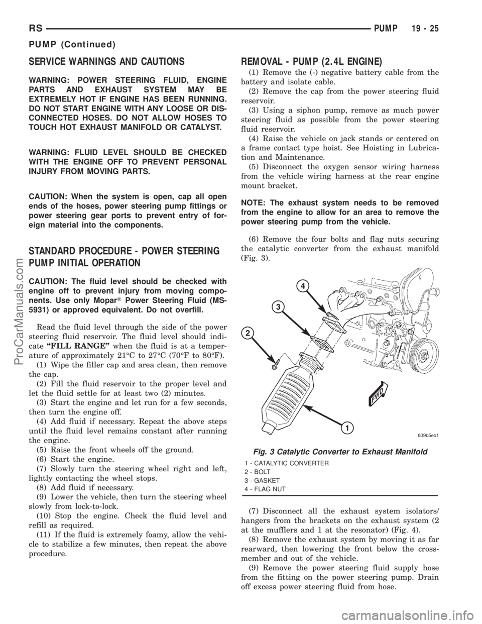
(6) Remove the four bolts and flag nuts securing
the catalytic converter from the exhaust manifold
(Fig. 3).
(7) Disconnect all the exhaust system isolators/
hangers from the brackets on the exhaust system (2
at the mufflers and 1 at the resonator) (Fig. 4).
(8) Remove the exhaust system by moving it as far
rearward, then lowering the front below the cross-
member and out of the vehicle.
(9) Remove the power steering fluid supply hose
from the fitting on the power steering pump. Drain
off excess power steering fluid from hose.
Fig. 3 Catalytic Converter to Exhaust Manifold
1 - CATALYTIC CONVERTER
2 - BOLT
3 - GASKET
4 - FLAG NUT
RSPUMP19-25
PUMP (Continued)
ProCarManuals.com
Page 1531 of 2321
(5) Low line pressure in all positions indicates a
defective pump, a clogged filter, or a stuck pressure
regulator valve.
GOVERNOR PRESSURE
Test only if transaxle shifts at wrong vehicle
speeds when throttle cable is correctly adjusted.
(1) Connect a 100 psi gauge to governor pressure
port. It is located at lower right side of case, below
differential cover (Fig. 2).
(2) Operate transaxle in third gear to read pres-
sures. The governor pressure should respond
smoothly to changes in mph and should return to 0
to 3 psi when vehicle is stopped. High pressure
(above 3 psi) at standstill will prevent the transaxle
from downshifting.
THROTTLE PRESSURE
No gauge port is provided for throttle pressure.
Incorrect throttle pressure should be suspected if
part throttle upshift speeds are either delayed or
occur too early in relation to vehicle speed. Engine
runaway on shifts can also be an indicator of low
throttle pressure setting, or misadjusted throttle
cable.
In no case should throttle pressure be adjusted
until the transaxle throttle cable adjustment has
been verified to be correct.
DIAGNOSIS AND TESTING - TORQUE
CONVERTER HOUSING FLUID LEAKAGE
When diagnosing converter housing fluid leaks,
three actions must be taken before repair:
(1) Verify proper transmission fluid level.
(2) Verify that the leak originates from the con-
verter housing area and is transmission fluid.
(3) Determine the true source of the leak.
Fluid leakage at or around the torque converter
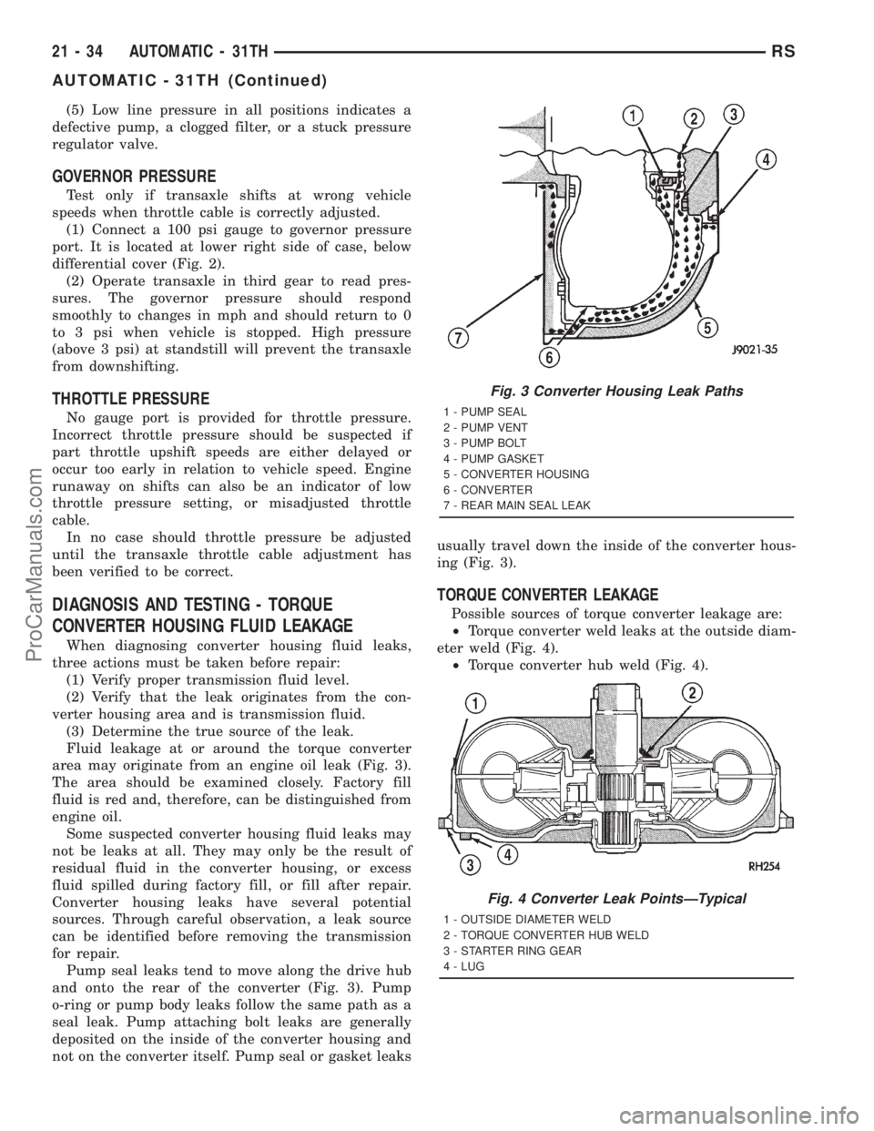
area may originate from an engine oil leak (Fig. 3).
The area should be examined closely. Factory fill
fluid is red and, therefore, can be distinguished from
engine oil.
Some suspected converter housing fluid leaks may
not be leaks at all. They may only be the result of
residual fluid in the converter housing, or excess
fluid spilled during factory fill, or fill after repair.
Converter housing leaks have several potential
sources. Through careful observation, a leak source
can be identified before removing the transmission
for repair.
Pump seal leaks tend to move along the drive hub
and onto the rear of the converter (Fig. 3). Pump
o-ring or pump body leaks follow the same path as a
seal leak. Pump attaching bolt leaks are generally
deposited on the inside of the converter housing and
not on the converter itself. Pump seal or gasket leaksusually travel down the inside of the converter hous-
ing (Fig. 3).
TORQUE CONVERTER LEAKAGE
Possible sources of torque converter leakage are:
²Torque converter weld leaks at the outside diam-
eter weld (Fig. 4).
²Torque converter hub weld (Fig. 4).
Fig. 3 Converter Housing Leak Paths
1 - PUMP SEAL
2 - PUMP VENT
3 - PUMP BOLT
4 - PUMP GASKET
5 - CONVERTER HOUSING
6 - CONVERTER
7 - REAR MAIN SEAL LEAK
Fig. 4 Converter Leak PointsÐTypical
1 - OUTSIDE DIAMETER WELD
2 - TORQUE CONVERTER HUB WELD
3 - STARTER RING GEAR
4 - LUG
21 - 34 AUTOMATIC - 31THRS
AUTOMATIC - 31TH (Continued)
ProCarManuals.com
Page 1611 of 2321
OPERATION
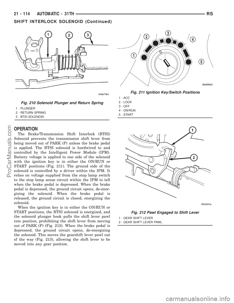
The Brake/Transmission Shift Interlock (BTSI)
Solenoid prevents the transmission shift lever from
being moved out of PARK (P) unless the brake pedal
is applied. The BTSI solenoid is hardwired to and
controlled by the Intelligent Power Module (IPM).
Battery voltage is applied to one side of the solenoid
with the ignition key is in either the ON/RUN or
START positions (Fig. 211). The ground side of the
solenoid is controlled by a driver within the IPM. It
relies on voltage supplied from the stop lamp switch
to the stop lamp sense circuit within the IPM to tell
when the brake pedal is depressed. When the brake
pedal is depressed, the ground circuit opens, de-ener-
gizing the solenoid. When the brake pedal is
released, the ground circuit is closed, energizing the
solenoid.
When the ignition key is in either the ON/RUN or
START positions, the BTSI solenoid is energized, and
the solenoid plunger hook pulls the shift lever pawl
into position, prohibiting the shift lever from moving
out of PARK (P) (Fig. 212). When the brake pedal is
depressed, the ground circuit opens, de-energizing
the solenoid. This moves the gearshift lever pawl out
of the way (Fig. 213), allowing the shift lever to be
moved into any gear position.
Fig. 210 Solenoid Plunger and Return Spring
1 - PLUNGER
2 - RETURN SPRING
3 - BTSI SOLENOID
Fig. 211 Ignition Key/Switch Positions
1 - ACC
2 - LOCK
3 - OFF
4 - ON/RUN
5-START
Fig. 212 Pawl Engaged to Shift Lever
1 - GEAR SHIFT LEVER
2 - GEAR SHIFT LEVER PAWL
21 - 114 AUTOMATIC - 31THRS
SHIFT INTERLOCK SOLENOID (Continued)
ProCarManuals.com
Page 1770 of 2321
OPERATION
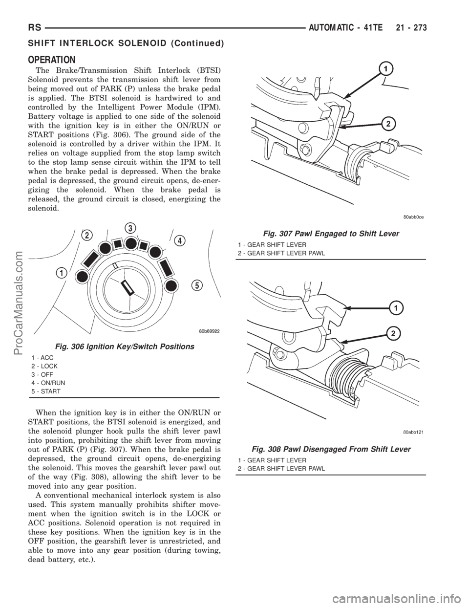
The Brake/Transmission Shift Interlock (BTSI)
Solenoid prevents the transmission shift lever from
being moved out of PARK (P) unless the brake pedal
is applied. The BTSI solenoid is hardwired to and
controlled by the Intelligent Power Module (IPM).
Battery voltage is applied to one side of the solenoid
with the ignition key is in either the ON/RUN or
START positions (Fig. 306). The ground side of the
solenoid is controlled by a driver within the IPM. It
relies on voltage supplied from the stop lamp switch
to the stop lamp sense circuit within the IPM to tell
when the brake pedal is depressed. When the brake
pedal is depressed, the ground circuit opens, de-ener-
gizing the solenoid. When the brake pedal is
released, the ground circuit is closed, energizing the
solenoid.
When the ignition key is in either the ON/RUN or
START positions, the BTSI solenoid is energized, and
the solenoid plunger hook pulls the shift lever pawl
into position, prohibiting the shift lever from moving
out of PARK (P) (Fig. 307). When the brake pedal is
depressed, the ground circuit opens, de-energizing
the solenoid. This moves the gearshift lever pawl out
of the way (Fig. 308), allowing the shift lever to be
moved into any gear position.
A conventional mechanical interlock system is also
used. This system manually prohibits shifter move-
ment when the ignition switch is in the LOCK or
ACC positions. Solenoid operation is not required in
these key positions. When the ignition key is in the
OFF position, the gearshift lever is unrestricted, and
able to move into any gear position (during towing,
dead battery, etc.).
Fig. 306 Ignition Key/Switch Positions
1 - ACC
2 - LOCK
3 - OFF
4 - ON/RUN
5-START
Fig. 307 Pawl Engaged to Shift Lever
1 - GEAR SHIFT LEVER
2 - GEAR SHIFT LEVER PAWL
Fig. 308 Pawl Disengaged From Shift Lever
1 - GEAR SHIFT LEVER
2 - GEAR SHIFT LEVER PAWL
RSAUTOMATIC - 41TE21 - 273
SHIFT INTERLOCK SOLENOID (Continued)
ProCarManuals.com
Page 1810 of 2321
DIAGNOSIS AND TESTING - COMMON
PROBLEM CAUSES
The majority of transaxle malfunctions are a result
of:
²Insufficient lubrication
²Incorrect lubricant
²Misassembled or damaged internal components
²Improper operation
HARD SHIFTING
Hard shifting may be caused by a misadjusted
crossover cable. If hard shifting is accompanied by
gear clash, synchronizer clutch and stop rings or gear
teeth may be worn or damaged.
Hard shifting may also be caused by a binding or
broken shift cover mechanism. Remove shift cover
and verify smooth operation. Replace as necessary.
Misassembled synchronizer components also cause
shifting problems. Incorrectly installed synchronizer
sleeves, keys, balls, or springs can cause shift prob-
lems.
NOISY OPERATION
Transaxle noise is most often a result of worn or
damaged components. Chipped, broken gear or syn-
chronizer teeth, and brinnelled, spalled bearings all
cause noise.
Abnormal wear and damage to the internal compo-
nents is frequently the end result of insufficient
lubricant.
SLIPS OUT OF GEAR
Transaxle disengagement may be caused by mis-
aligned or damaged shift components, or worn teeth
on the drive gears or synchronizer components. Incor-
rect assembly also causes gear disengagement. Check
for missing snap rings.
LOW LUBRICANT LEVEL
Insufficient transaxle lubricant is usually the
result of leaks, or inaccurate fluid level check or refill
method. Leakage is evident by the presence of oil
around the leak point. If leakage is not evident, the
condition is probably the result of an underfill.
If air±powered lubrication equipment is used to fill
a transaxle, be sure the equipment is properly cali-
brated. Equipment out of calibration can lead to an
underfill condition.
CLUTCH PROBLEMS
Worn, damaged, or misaligned clutch components
can cause difficult shifting, gear clash, and noise.
A worn or damaged clutch disc, pressure plate, or
release bearing can cause hard shifting and gear
clash.
REMOVAL
REMOVAL - 2.4L GAS
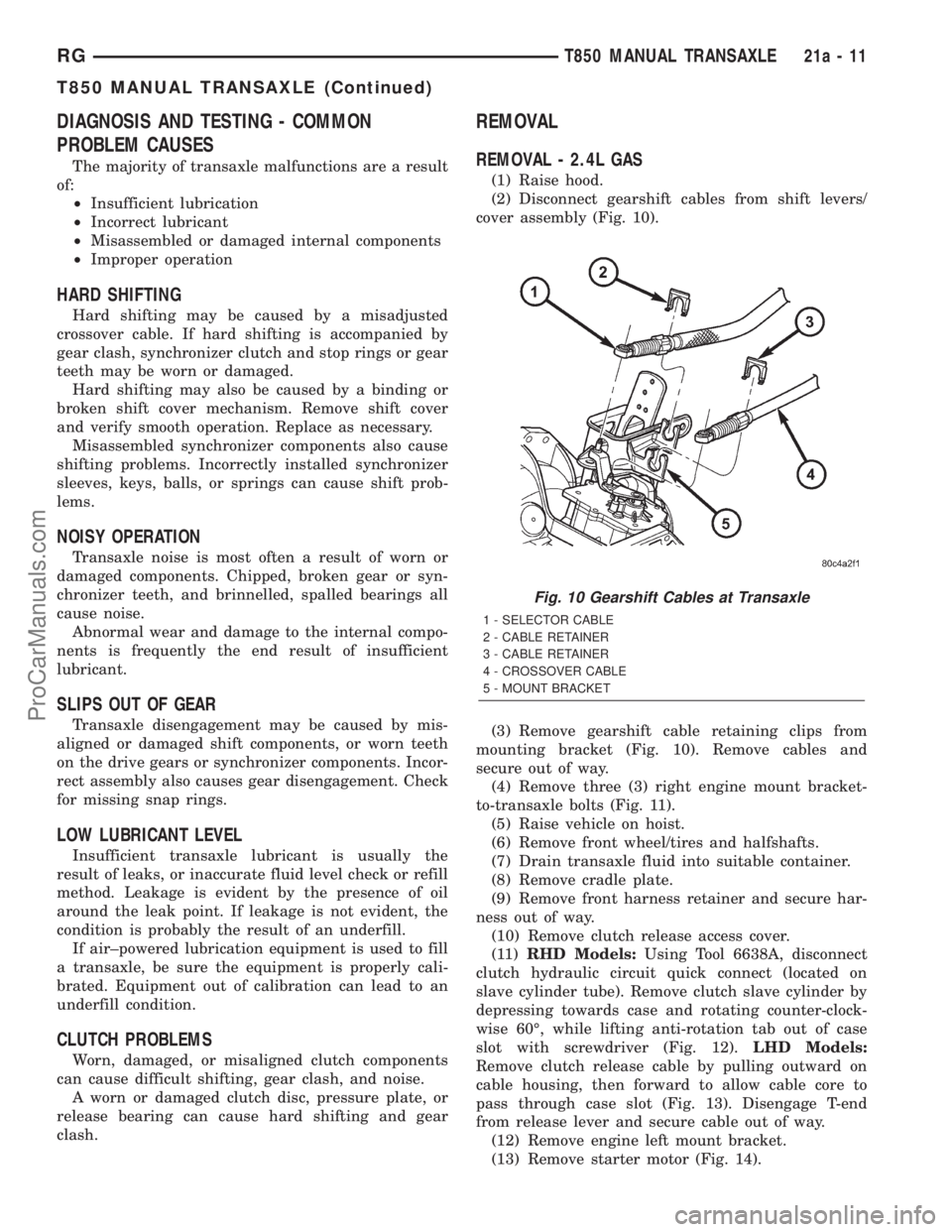
(1) Raise hood.
(2) Disconnect gearshift cables from shift levers/
cover assembly (Fig. 10).
(3) Remove gearshift cable retaining clips from
mounting bracket (Fig. 10). Remove cables and
secure out of way.
(4) Remove three (3) right engine mount bracket-
to-transaxle bolts (Fig. 11).
(5) Raise vehicle on hoist.
(6) Remove front wheel/tires and halfshafts.
(7) Drain transaxle fluid into suitable container.
(8) Remove cradle plate.
(9) Remove front harness retainer and secure har-
ness out of way.
(10) Remove clutch release access cover.
(11)RHD Models:Using Tool 6638A, disconnect
clutch hydraulic circuit quick connect (located on
slave cylinder tube). Remove clutch slave cylinder by
depressing towards case and rotating counter-clock-
wise 60É, while lifting anti-rotation tab out of case
slot with screwdriver (Fig. 12).LHD Models:
Remove clutch release cable by pulling outward on
cable housing, then forward to allow cable core to
pass through case slot (Fig. 13). Disengage T-end
from release lever and secure cable out of way.
(12) Remove engine left mount bracket.
(13) Remove starter motor (Fig. 14).
Fig. 10 Gearshift Cables at Transaxle
1 - SELECTOR CABLE
2 - CABLE RETAINER
3 - CABLE RETAINER
4 - CROSSOVER CABLE
5 - MOUNT BRACKET
RGT850 MANUAL TRANSAXLE21a-11
T850 MANUAL TRANSAXLE (Continued)
ProCarManuals.com