2001 DODGE TOWN AND COUNTRY hood release
[x] Cancel search: hood releasePage 985 of 2321

BODY CONTROL MODULE C3 - BLACK/WHITE 34 WAY
CAV CIRCUIT FUNCTION
1 G23 20VT/DB (POWER SLIDING
DOOR)SLIDING DOORS OVERHEAD SWITCH MUX
2 D23 20WT/BR FLASH PROGRAM ENABLE
3 G152 20VT/GY (POWER SLIDING
DOOR)RIGHT SLIDING DOOR WAKE UP SIGNAL
4 G151 20VT/BR (POWER SLIDING
DOOR)LEFT SLIDING DOOR WAKE UP SIGNAL
5 G76 20VT/YL RIGHT SLIDING DOOR AJAR SWITCH SENSE
6 G75 20VT (LHD) LEFT FRONT DOOR AJAR SWITCH SENSE
6 G74 20VT/WT (RHD) RIGHT FRONT DOOR AJAR SWITCH SENSE
7 G74 20VT/WT (LHD) RIGHT FRONT DOOR AJAR SWITCH SENSE
7 G75 20VT (RHD) LEFT FRONT DOOR AJAR SWITCH SENSE
8 G77 20VT/GY LEFT SLIDING DOOR AJAR SWITCH SENSE
9 E10 20OR/GY (ATC ) (3 ZONE HVAC) PANEL LAMPS DRIVER (REAR BLOWER SWITCH)
10 - -
11 L162 20WT/VT (BUILT-UP-EXPORT) RIGHT SIDE REPEATER LAMP FEED
12 G42 20VT/YL (POWER SLIDING
DOOR)RIGHT SLIDING DOOR PILLAR SWITCH MUX
13 G165 20VT/GY LIFTGATE CYLINDER LOCK SWITCH MUX
14 G163 20VT/LB LEFT CYLINDER LOCK SWITCH MUX
15 G162 20VT/WT RIGHT CYLINDER LOCK SWITCH MUX
16 - -
17 F503 20WT/PK IGNITION SWITCH OUTPUT (RUN)
18 G41 20VT/DG (POWER SLIDING
DOOR)LEFT SLIDING DOOR PILLAR SWITCH MUX
19 L163 20WT/BR (BUILT-UP-EXPORT) LEFT SIDE REPEATER LAMP FEED
20 N4 18DB/WT FUEL LEVEL SENSOR SIGNAL
21 G161 20VT/DG (LHD) LEFT DOOR LOCK SWITCH MUX
21 G160 20VT/LG (RHD) RIGHT DOOR LOCK SWITCH MUX
22 G161 20VT/DG (RHD) LEFT DOOR LOCK SWITCH MUX
22 G160 20VT/LG (LHD) RIGHT DOOR LOCK SWITCH MUX
23 D25 20WT/VT PCI BUS
24 - -
25 M11 20YL/VT COURTESY LAMPS DRIVER
26 P31 20TN/YL (POWER RELEASE)
(EXCEPT BUILT-UP-EXPORT LHD SWB
GAS)LIFTGATE RELEASE DRIVER
26 P31 20TN/DG (POWER RELEASE)
(BUILT-UP-EXPORT LHD SWB GAS)LIFTGATE RELEASE DRIVER
27 - -
28 - -
29 G78 20VT/OR LIFTGATE AJAR SWITCH SENSE
30 G70 20VT/LB HOOD AJAR SWITCH SENSE
31 F500 18DG/PK FUSED IGNITION SWITCH OUTPUT (RUN)
32 - -
33 M21 20YL/BR COURTESY LAMPS DRIVER
34 M27 20YL/LB READING LAMPS DRIVER
8Wa - 80 - 12 8W-80 CONNECTOR PIN-OUTSRG
ProCarManuals.com
Page 1395 of 2321
FRONT FASCIA
REMOVAL
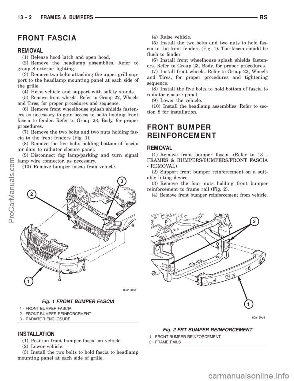
(1) Release hood latch and open hood.
(2) Remove the headlamp assemblies. Refer to
group 8 exterior lighting.
(3) Remove two bolts attaching the upper grill sup-
port to the headlamp mounting panel at each side of
the grille.
(4) Hoist vehicle and support with safety stands.
(5)
Remove front wheels. Refer to Group 22, Wheels
and Tires, for proper procedures and sequence.
(6) Remove front wheelhouse splash shields fasten-
ers as necessary to gain access to bolts holding front
fascia to fender. Refer to Group 23, Body, for proper
procedures.
(7) Remove the two bolts and two nuts holding fas-
cia to the front fenders (Fig. 1).
(8) Remove the five bolts holding bottom of fascia/
air dam to radiator closure panel.
(9) Disconnect fog lamp/parking and turn signal
lamp wire connector, as necessary.
(10) Remove bumper fascia from vehicle.
INSTALLATION
(1) Position front bumper fascia on vehicle.
(2) Lower vehicle.
(3) Install the two bolts to hold fascia to headlamp
mounting panel at each side of grille.(4) Raise vehicle.
(5) Install the two bolts and two nuts to hold fas-
cia to the front fenders (Fig. 1). The fascia should be
flush to fender.
(6) Install front wheelhouse splash shields fasten-
ers. Refer to Group 23, Body, for proper procedures.
(7) Install front wheels. Refer to Group 22, Wheels
and Tires, for proper procedures and tightening
sequence.
(8) Install the five bolts to hold bottom of fascia to
radiator closure panel.
(9) Lower the vehicle.
(10) Install the headlamp assemblies. Refer to sec-
tion 8 for installation.
FRONT BUMPER
REINFORCEMENT
REMOVAL
(1) Remove front bumper fascia. (Refer to 13 -
FRAMES & BUMPERS/BUMPERS/FRONT FASCIA
- REMOVAL)
(2) Support front bumper reinforcement on a suit-
able lifting device.
(3) Remove the four nuts holding front bumper
reinforcement to frame rail (Fig. 2).
(4) Remove front bumper reinforcement from vehicle.
Fig. 1 FRONT BUMPER FASCIA
1 - FRONT BUMPER FASCIA
2 - FRONT BUMPER REINFORCEMENT
3 - RADIATOR ENCLOSURE
Fig. 2 FRT BUMPER REINFORCEMENT
1 - FRONT BUMPER REINFORCEMENT
2 - FRAME RAILS
13 - 2 FRAMES & BUMPERSRS
ProCarManuals.com
Page 1810 of 2321
DIAGNOSIS AND TESTING - COMMON
PROBLEM CAUSES
The majority of transaxle malfunctions are a result
of:
²Insufficient lubrication
²Incorrect lubricant
²Misassembled or damaged internal components
²Improper operation
HARD SHIFTING
Hard shifting may be caused by a misadjusted
crossover cable. If hard shifting is accompanied by
gear clash, synchronizer clutch and stop rings or gear
teeth may be worn or damaged.
Hard shifting may also be caused by a binding or
broken shift cover mechanism. Remove shift cover
and verify smooth operation. Replace as necessary.
Misassembled synchronizer components also cause
shifting problems. Incorrectly installed synchronizer
sleeves, keys, balls, or springs can cause shift prob-
lems.
NOISY OPERATION
Transaxle noise is most often a result of worn or
damaged components. Chipped, broken gear or syn-
chronizer teeth, and brinnelled, spalled bearings all
cause noise.
Abnormal wear and damage to the internal compo-
nents is frequently the end result of insufficient
lubricant.
SLIPS OUT OF GEAR
Transaxle disengagement may be caused by mis-
aligned or damaged shift components, or worn teeth
on the drive gears or synchronizer components. Incor-
rect assembly also causes gear disengagement. Check
for missing snap rings.
LOW LUBRICANT LEVEL
Insufficient transaxle lubricant is usually the
result of leaks, or inaccurate fluid level check or refill
method. Leakage is evident by the presence of oil
around the leak point. If leakage is not evident, the
condition is probably the result of an underfill.
If air±powered lubrication equipment is used to fill
a transaxle, be sure the equipment is properly cali-
brated. Equipment out of calibration can lead to an
underfill condition.
CLUTCH PROBLEMS
Worn, damaged, or misaligned clutch components
can cause difficult shifting, gear clash, and noise.
A worn or damaged clutch disc, pressure plate, or
release bearing can cause hard shifting and gear
clash.
REMOVAL
REMOVAL - 2.4L GAS
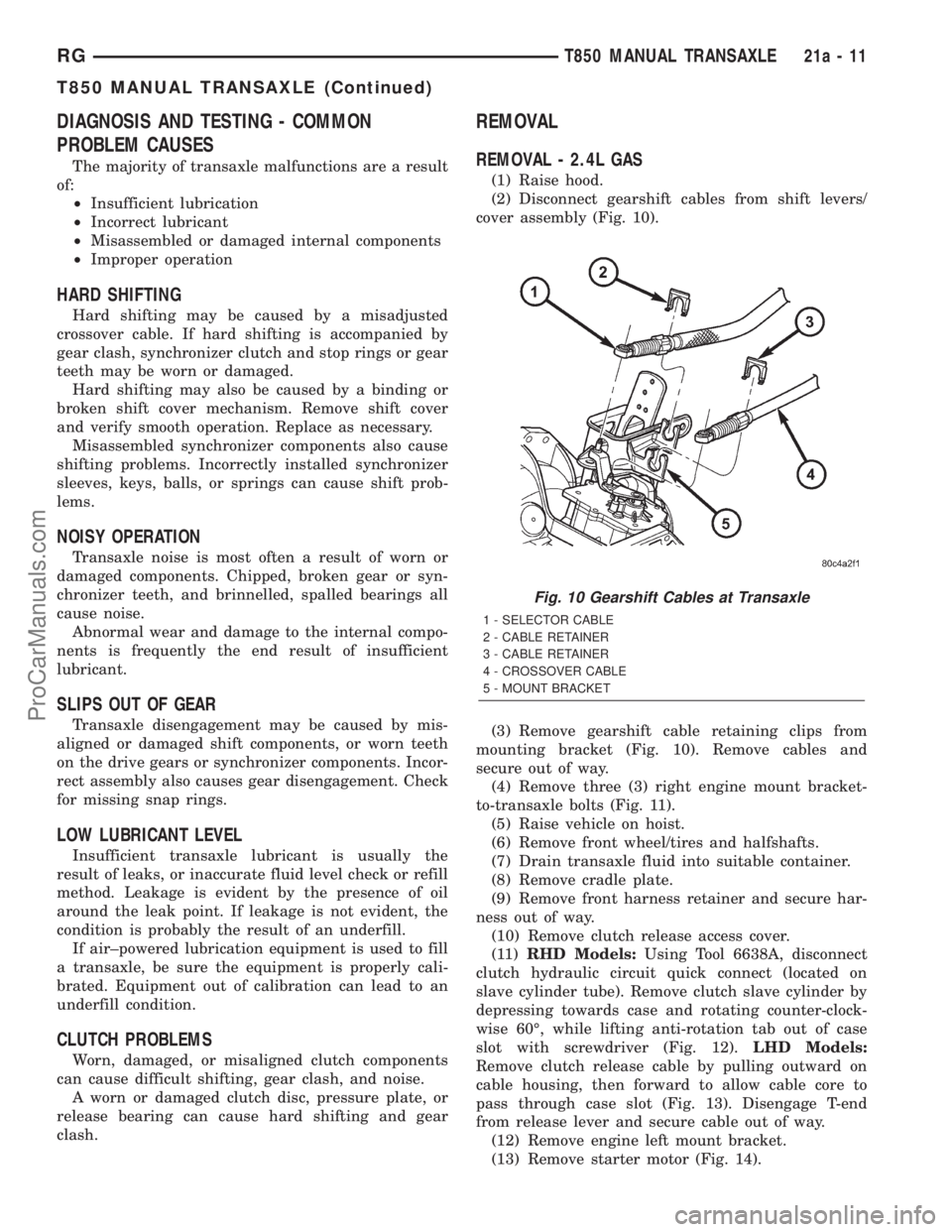
(1) Raise hood.
(2) Disconnect gearshift cables from shift levers/
cover assembly (Fig. 10).
(3) Remove gearshift cable retaining clips from
mounting bracket (Fig. 10). Remove cables and
secure out of way.
(4) Remove three (3) right engine mount bracket-
to-transaxle bolts (Fig. 11).
(5) Raise vehicle on hoist.
(6) Remove front wheel/tires and halfshafts.
(7) Drain transaxle fluid into suitable container.
(8) Remove cradle plate.
(9) Remove front harness retainer and secure har-
ness out of way.
(10) Remove clutch release access cover.
(11)RHD Models:Using Tool 6638A, disconnect
clutch hydraulic circuit quick connect (located on
slave cylinder tube). Remove clutch slave cylinder by
depressing towards case and rotating counter-clock-
wise 60É, while lifting anti-rotation tab out of case
slot with screwdriver (Fig. 12).LHD Models:
Remove clutch release cable by pulling outward on
cable housing, then forward to allow cable core to
pass through case slot (Fig. 13). Disengage T-end
from release lever and secure cable out of way.
(12) Remove engine left mount bracket.
(13) Remove starter motor (Fig. 14).
Fig. 10 Gearshift Cables at Transaxle
1 - SELECTOR CABLE
2 - CABLE RETAINER
3 - CABLE RETAINER
4 - CROSSOVER CABLE
5 - MOUNT BRACKET
RGT850 MANUAL TRANSAXLE21a-11
T850 MANUAL TRANSAXLE (Continued)
ProCarManuals.com
Page 1922 of 2321
(4) Allow the repaired area to cool and verify the
repair.
(5) Install trim panel.
SPECIFICATIONS
BODY LUBRICATION SPECIFICATIONS
LUBRICATION REQUIREMENTS
Body mechanisms and linkages should be
inspected, cleaned, and lubricated, as required, to
maintain ease of operation and to provide protectionagainst rust and wear. When performing other under
hood services, the hood latch release mechanism and
safety catch should be inspected, cleaned, and lubri-
cated. During the winter season, external door lock
cylinders should be lubricated to assure proper oper-
ation when exposed to water and ice.
Prior to the application of any lubricant, the parts
concerned should be wiped clean to remove dust and
grit. If necessary, a suitable solvent can be used to
clean the item to be lubricated. After lubricating a
component, any excess oil or grease should be
removed.
LUBRICANT APPLICATION
DOOR LOCK CYLINDERS
(1) Apply a small amount of lubricant directly into
the lock cylinder.
(2) Apply a small amount of lubricant to the key.
(3) Insert key into lock cylinder and cycle the
mechanism from the locked to the unlocked position.
NOTE: Do not add more lubricant.
(4) Cycle the lock cylinder mechanism several
times to allow the lubricant to flow throughout the
cylinder.
(5) Wipe all lubricant from exterior of lock cylinder
and key.
ALL OTHER BODY MECHANISMS
(1) Clean component as described above.
(2) Apply specified lubricant to all pivoting and
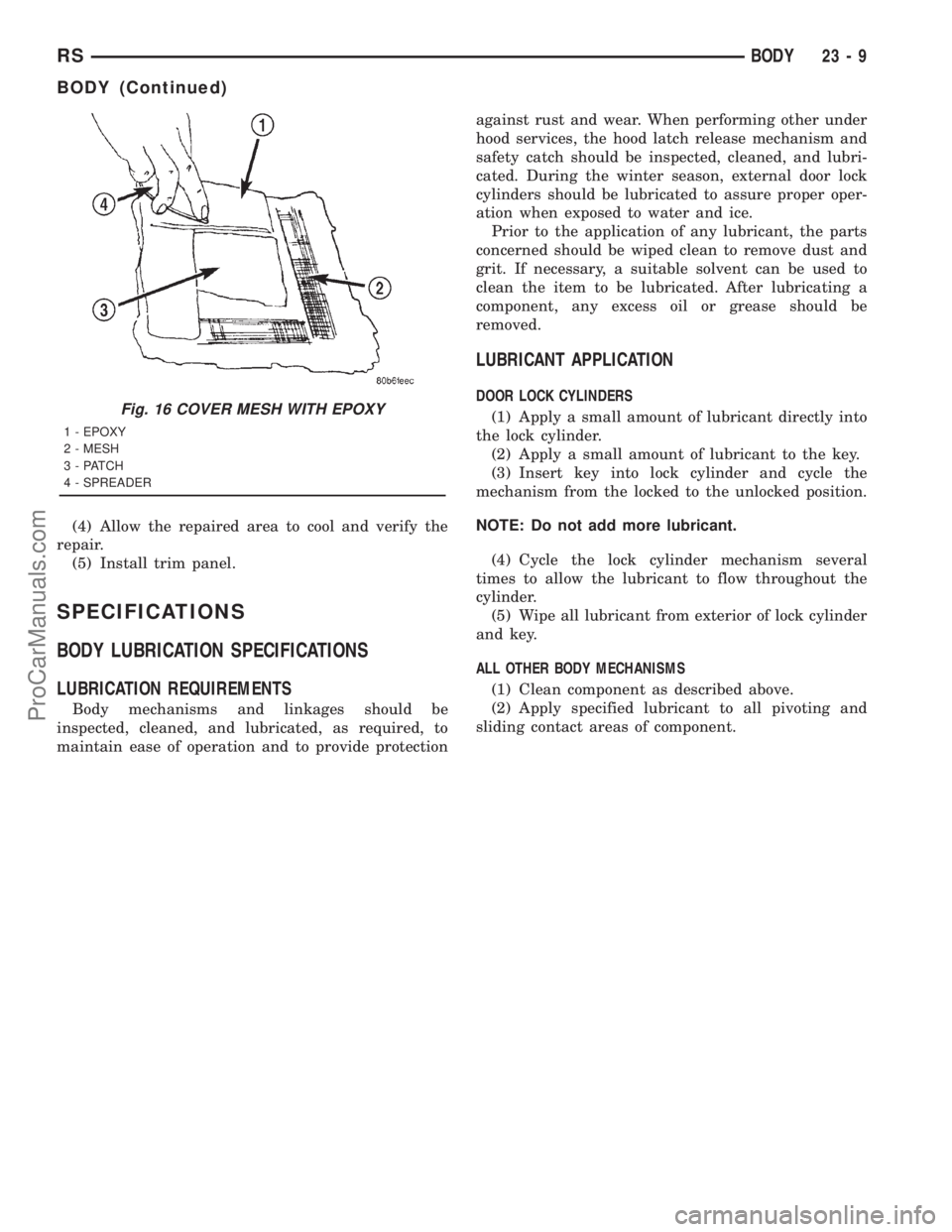
sliding contact areas of component.Fig. 16 COVER MESH WITH EPOXY
1 - EPOXY
2 - MESH
3 - PATCH
4 - SPREADER
RSBODY23-9
BODY (Continued)
ProCarManuals.com
Page 2103 of 2321
COWL GRILLE
REMOVAL
(1) Remove wiper arms. (Refer to 8 - ELECTRI-
CAL/WIPERS/WASHERS/WIPER ARMS -
REMOVAL)
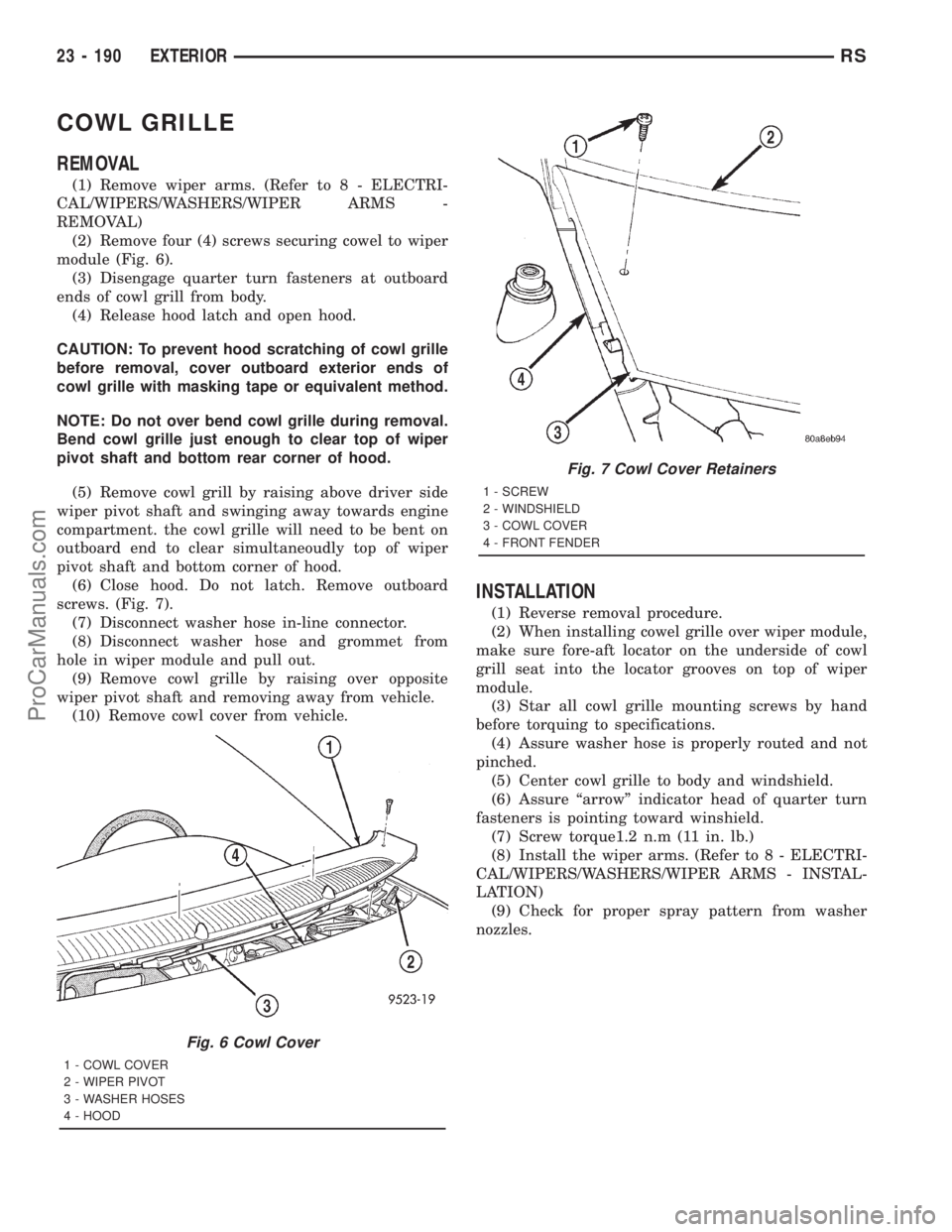
(2) Remove four (4) screws securing cowel to wiper
module (Fig. 6).
(3) Disengage quarter turn fasteners at outboard
ends of cowl grill from body.
(4) Release hood latch and open hood.
CAUTION: To prevent hood scratching of cowl grille
before removal, cover outboard exterior ends of
cowl grille with masking tape or equivalent method.
NOTE: Do not over bend cowl grille during removal.
Bend cowl grille just enough to clear top of wiper
pivot shaft and bottom rear corner of hood.
(5) Remove cowl grill by raising above driver side
wiper pivot shaft and swinging away towards engine
compartment. the cowl grille will need to be bent on
outboard end to clear simultaneoudly top of wiper
pivot shaft and bottom corner of hood.
(6) Close hood. Do not latch. Remove outboard
screws. (Fig. 7).
(7) Disconnect washer hose in-line connector.
(8) Disconnect washer hose and grommet from
hole in wiper module and pull out.
(9) Remove cowl grille by raising over opposite
wiper pivot shaft and removing away from vehicle.
(10) Remove cowl cover from vehicle.
INSTALLATION
(1) Reverse removal procedure.
(2) When installing cowel grille over wiper module,
make sure fore-aft locator on the underside of cowl
grill seat into the locator grooves on top of wiper
module.
(3) Star all cowl grille mounting screws by hand
before torquing to specifications.
(4) Assure washer hose is properly routed and not
pinched.
(5) Center cowl grille to body and windshield.
(6) Assure ªarrowº indicator head of quarter turn
fasteners is pointing toward winshield.
(7) Screw torque1.2 n.m (11 in. lb.)
(8) Install the wiper arms. (Refer to 8 - ELECTRI-
CAL/WIPERS/WASHERS/WIPER ARMS - INSTAL-
LATION)
(9) Check for proper spray pattern from washer
nozzles.
Fig. 6 Cowl Cover
1 - COWL COVER
2 - WIPER PIVOT
3 - WASHER HOSES
4 - HOOD
Fig. 7 Cowl Cover Retainers
1 - SCREW
2 - WINDSHIELD
3 - COWL COVER
4 - FRONT FENDER
23 - 190 EXTERIORRS
ProCarManuals.com
Page 2107 of 2321
(5) Install fuel filler housing to outer quarter
panel.
(6) Verify that all clips on fuel filler housing are
fully engaged to outer quarter panel.
(7) Engage fuel filler lockout link into clip on fuel
fill blocker latch arm.
(8) Install water shield patch covering access hole
in C-pillar.
(9) Install left quarter trim panel.
GRILLE OPENING
REINFORCEMENT
REMOVAL
(1) Release hood latch and open hood.
(2) Remove bolts attaching hood latch to cross-
member and position latch out of the way.
(3) Remove radiator sight shield.
(4) Remove engine air inlet resonator.
(5) Remove hood cable.
(6) Remove hood prop rod.
(7) Remove screw attaching coolant recovery bottle
to crossmember.
(8) Remove bolts attaching radiator isolators to
crossmember.
(9) Remove bolts attaching ends of crossmember to
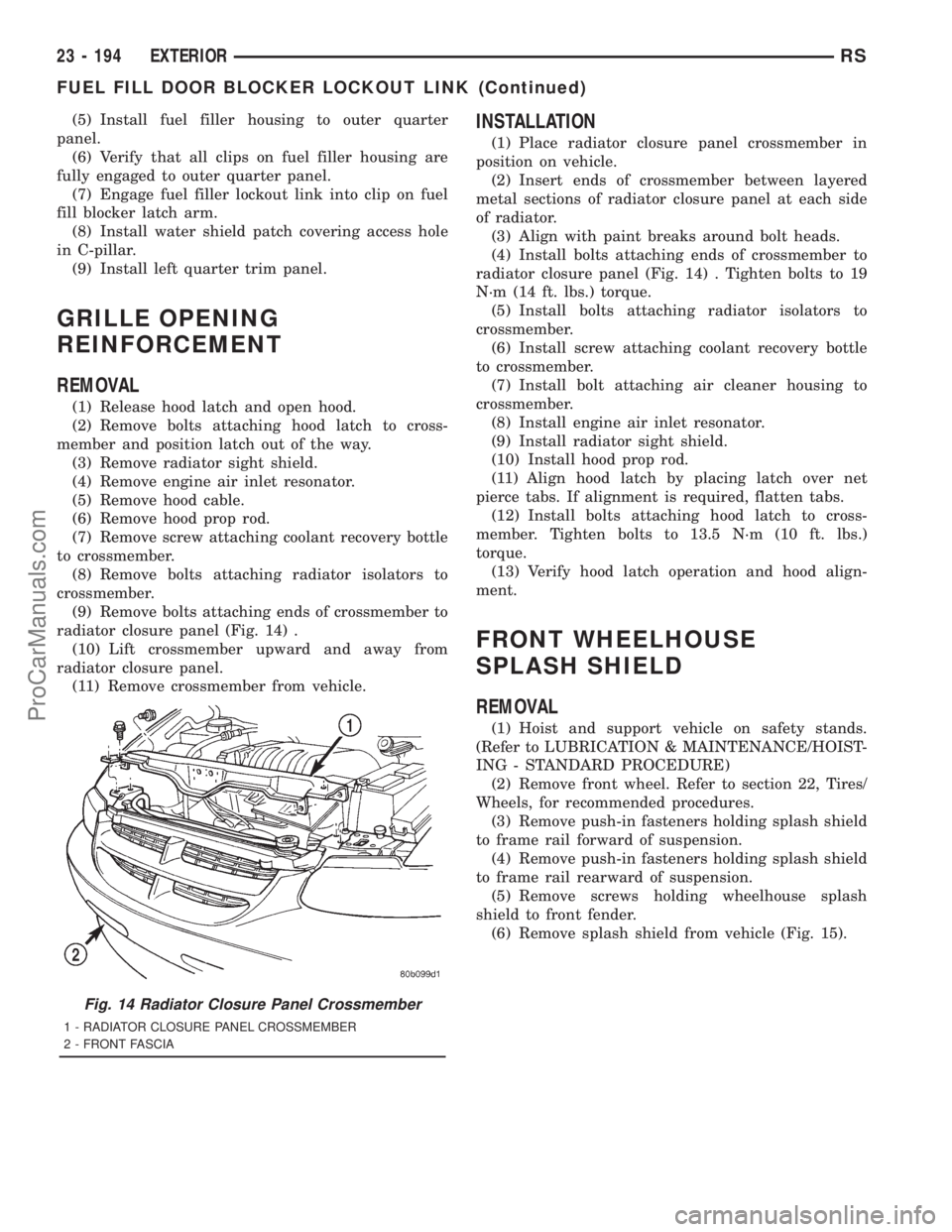
radiator closure panel (Fig. 14) .
(10) Lift crossmember upward and away from
radiator closure panel.
(11) Remove crossmember from vehicle.
INSTALLATION
(1) Place radiator closure panel crossmember in
position on vehicle.
(2) Insert ends of crossmember between layered
metal sections of radiator closure panel at each side
of radiator.
(3) Align with paint breaks around bolt heads.
(4) Install bolts attaching ends of crossmember to
radiator closure panel (Fig. 14) . Tighten bolts to 19
N´m (14 ft. lbs.) torque.
(5) Install bolts attaching radiator isolators to
crossmember.
(6) Install screw attaching coolant recovery bottle
to crossmember.
(7) Install bolt attaching air cleaner housing to
crossmember.
(8) Install engine air inlet resonator.
(9) Install radiator sight shield.
(10) Install hood prop rod.
(11) Align hood latch by placing latch over net
pierce tabs. If alignment is required, flatten tabs.
(12) Install bolts attaching hood latch to cross-
member. Tighten bolts to 13.5 N´m (10 ft. lbs.)
torque.
(13) Verify hood latch operation and hood align-
ment.
FRONT WHEELHOUSE
SPLASH SHIELD
REMOVAL
(1) Hoist and support vehicle on safety stands.
(Refer to LUBRICATION & MAINTENANCE/HOIST-
ING - STANDARD PROCEDURE)
(2) Remove front wheel. Refer to section 22, Tires/
Wheels, for recommended procedures.
(3) Remove push-in fasteners holding splash shield
to frame rail forward of suspension.
(4) Remove push-in fasteners holding splash shield
to frame rail rearward of suspension.
(5) Remove screws holding wheelhouse splash
shield to front fender.
(6) Remove splash shield from vehicle (Fig. 15).
Fig. 14 Radiator Closure Panel Crossmember
1 - RADIATOR CLOSURE PANEL CROSSMEMBER
2 - FRONT FASCIA
23 - 194 EXTERIORRS
FUEL FILL DOOR BLOCKER LOCKOUT LINK (Continued)
ProCarManuals.com
Page 2112 of 2321
HOOD
TABLE OF CONTENTS
page page
HINGE
REMOVAL.............................199
INSTALLATION..........................199
HOOD
REMOVAL.............................200
INSTALLATION..........................200
LATCH
REMOVAL.............................200INSTALLATION..........................200
LATCH RELEASE CABLE
REMOVAL.............................201
INSTALLATION..........................201
LATCH STRIKER
REMOVAL.............................201
INSTALLATION..........................201
HINGE
REMOVAL
(1) Remove hood.
(2) Remove wiper unit. Refer to Group 8K, Wind-
shield Wipers and Washers, for procedure.
(3) Mark all bolt and hinge attachment locations
with a grease pencil or other suitable device to pro-
vide reference marks for installation.
(4) Remove pivot bolt from the body half of hood
hinge.
(5) Remove bolts attaching body half of hood hinge
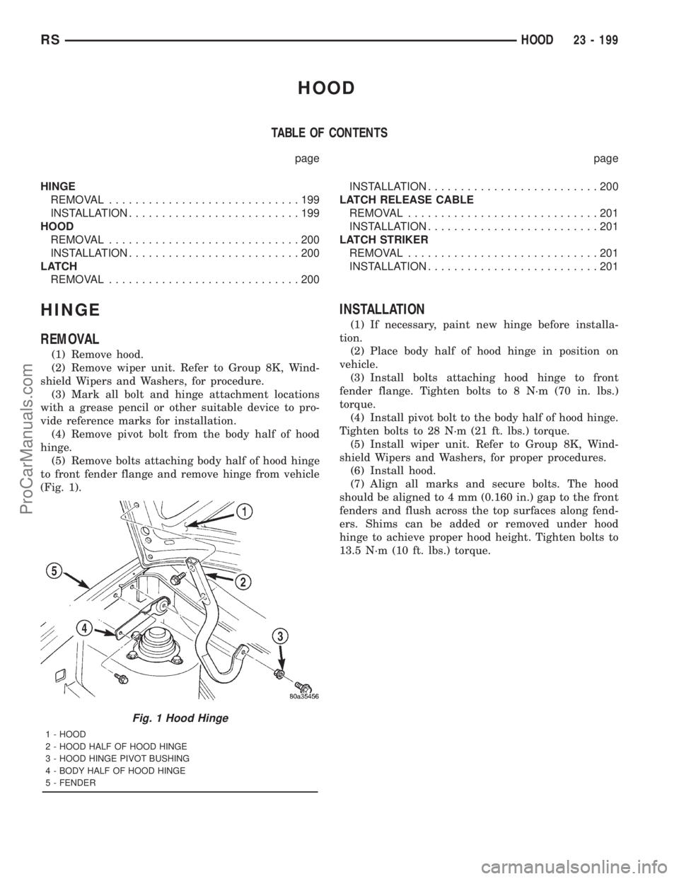
to front fender flange and remove hinge from vehicle
(Fig. 1).
INSTALLATION
(1) If necessary, paint new hinge before installa-
tion.
(2) Place body half of hood hinge in position on
vehicle.
(3) Install bolts attaching hood hinge to front
fender flange. Tighten bolts to 8 N´m (70 in. lbs.)
torque.
(4) Install pivot bolt to the body half of hood hinge.
Tighten bolts to 28 N´m (21 ft. lbs.) torque.
(5) Install wiper unit. Refer to Group 8K, Wind-
shield Wipers and Washers, for proper procedures.
(6) Install hood.
(7) Align all marks and secure bolts. The hood
should be aligned to 4 mm (0.160 in.) gap to the front
fenders and flush across the top surfaces along fend-
ers. Shims can be added or removed under hood
hinge to achieve proper hood height. Tighten bolts to
13.5 N´m (10 ft. lbs.) torque.
Fig. 1 Hood Hinge
1 - HOOD
2 - HOOD HALF OF HOOD HINGE
3 - HOOD HINGE PIVOT BUSHING
4 - BODY HALF OF HOOD HINGE
5 - FENDER
RSHOOD23 - 199
ProCarManuals.com
Page 2113 of 2321
HOOD
REMOVAL
(1) Raise hood to full up position.
(2) Mark all bolt and hinge attachment locations
with a grease pencil or other suitable device to pro-
vide reference marks for installation.
(3) Remove the top bolts attaching hood to hinge
and loosen the bottom bolts until they can be
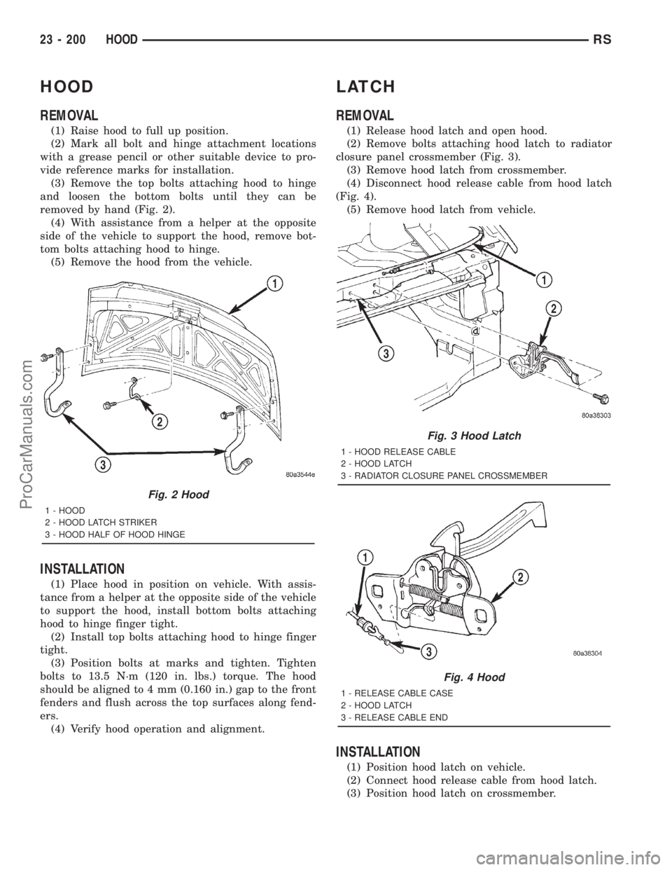
removed by hand (Fig. 2).
(4) With assistance from a helper at the opposite
side of the vehicle to support the hood, remove bot-
tom bolts attaching hood to hinge.
(5) Remove the hood from the vehicle.
INSTALLATION
(1) Place hood in position on vehicle. With assis-
tance from a helper at the opposite side of the vehicle
to support the hood, install bottom bolts attaching
hood to hinge finger tight.
(2) Install top bolts attaching hood to hinge finger
tight.
(3) Position bolts at marks and tighten. Tighten
bolts to 13.5 N´m (120 in. lbs.) torque. The hood
should be aligned to 4 mm (0.160 in.) gap to the front
fenders and flush across the top surfaces along fend-
ers.
(4) Verify hood operation and alignment.
LATCH
REMOVAL
(1) Release hood latch and open hood.
(2) Remove bolts attaching hood latch to radiator
closure panel crossmember (Fig. 3).
(3) Remove hood latch from crossmember.
(4) Disconnect hood release cable from hood latch
(Fig. 4).
(5) Remove hood latch from vehicle.
INSTALLATION
(1) Position hood latch on vehicle.
(2) Connect hood release cable from hood latch.
(3) Position hood latch on crossmember.
Fig. 2 Hood
1 - HOOD
2 - HOOD LATCH STRIKER
3 - HOOD HALF OF HOOD HINGE
Fig. 3 Hood Latch
1 - HOOD RELEASE CABLE
2 - HOOD LATCH
3 - RADIATOR CLOSURE PANEL CROSSMEMBER
Fig. 4 Hood
1 - RELEASE CABLE CASE
2 - HOOD LATCH
3 - RELEASE CABLE END
23 - 200 HOODRS
ProCarManuals.com