2001 DODGE TOWN AND COUNTRY change wheel
[x] Cancel search: change wheelPage 147 of 2321
lock the front wheels first. Any torque transfer from
the rear axle to the front axle disturbs the ABS/brak-
ing system and causes potential instabilities on a
slippery surface. The BOC de-couples the rear driv-
eline as soon the rear wheels begin to spin faster
than the front wheels (front wheels locked) in order
to provide increased braking stability. Furthermore
the BOC also reduces the likelihood of throttle off
over-steer during cornering. In a throttle off maneu-
ver, the BOC once again de-couples the rear driveline
forcing all the engine brake torque to the front
wheels. This eliminates the chance of lateral slip on
the rear axle and increases it on the front. The vehi-
cle will therefore tend to understeer, a situation
which is considered easier to manage in most circum-
stances. During this maneuver, and during the ABS
braking event, the BOC does not transmit torque
through to the rear wheels. The rear driveline mod-
ule, with the BOC, will perform the same as a front
wheel drive vehicle during these events. The gear
ratio offset between the front and rear differentials
force the BOC into the overrunning mode most of the
time. This allows BOC to significantly reduce the
rolling resistance of the vehicle, which improves fuel
consumption, allows the downsizing of the driveline
components, and prevents the PTU and propshaft
joints from overheating.
OPERATION
In order to achieve all-wheel drive operation in
reverse, the overrunning clutch locking functional
direction must be reversible. The bi-directional over-
running clutch (BOC) changes the operational mode
direction depending on the propeller shaft direction.
The propeller shaft rotates in the clockwise (when
viewed from the front) direction when the vehicle is
moving forward, which indexes the BOC to the for-
ward overrunning position. When the vehicle is in
reverse, the propeller shaft will rotate counter-clock-
wise and index the BOC to the reverse overrunning
position.
The BOC acts as a mechanical stator. It is active
(transmitting torque), or it is not active and in over-
running mode (not transmitting torque). This ªall or
nothingº approach to torque transfer would cause a
sudden application of all available power to the rear
wheels, which is not desirable. Therefore it is run in
series with a viscous coupler to smooth, dampen, and
limit the transmission of torque to the rear axle and
to prevent a step style torque input to the rear axle.
STEADY STATE, LOW TO MODERATE SPEED, NO
FRONT WHEEL SLIP, FORWARD DIRECTION
During normal driving conditions, (no wheel slip),
the inner shaft (front axle) and outer race (viscous
coupler) are running at different speeds due to the
different gear ratios between the front and rear dif-
ferentials. In this condition, the outer race is always
spinning faster (overdriving between 5-32 rpm) than
the inner shaft. When the BOC (Fig. 29) is running
under these conditions, at low vehicle speeds the
drag shoes and the cage keep the rollers up on the
left side (forward side) of the inner shaft flats. This is
what is known as ªoverrunning mode.º Notice that
when the clutch is in overrunning mode, the rollers
are spinning clockwise and with the outer race, thus
no torque is being transferred.
NOTE: Low speed, forward and reverse operation is
identical, just in opposite directions. (Fig. 29)
shows forward direction in reverse the rollers are
on the other side of the flats due to a reversal of
the cage force.
TRANSIENT CONDITION (BOC LOCKED), FRONT
WHEEL SLIP, FORWARD DIRECTION
When the front wheels lose traction and begin to
slip, the propeller shaft and rear axle pinion speed
difference decreases to zero. At this point the input
shaft (cam) becomes the driving member of the BOC
(Fig. 30), compressing the rollers against the outer
race. This locks the input shaft with the outer race
and transmits torque to the housing of the viscous
coupler, that in turn transmits torque to the rear
axle pinion. It should also be noted that when the
device is locked, the inner shaft and the outer race
are rotating at the same speed. The rollers are
pinched at this point and will stay locked until a
torque reversal (no front wheel slip) occurs. When
locked, the viscous coupler slips during the torque
transfer and the amount of torque transferred is
dependent on the coupling characteristic and the
amount of front wheel slip.
3 - 38 REAR DRIVELINE MODULERS
BI-DIRECTIONAL OVERRUNNING CLUTCH (Continued)
ProCarManuals.com
Page 172 of 2321

observed if the automatic adjuster is working prop-
erly. If one or more adjusters do not function prop-
erly, the respective drum must be removed for
adjuster servicing.
BRAKE LINES
DESCRIPTION - BRAKE TUBES AND HOSES
The brake tubes are steel with a corrosion-resis-
tant nylon coating applied to the external surfaces.
The flex hoses are made of reinforced rubber with fit-
tings at each end.
The primary and secondary brake tubes leading
from the master cylinder to the ABS ICU Hydraulic
Control Unit (HCU) or the non-ABS junction block
have a special flexible section. This flexible section is
required due to cradle movement while the vehicle is
in motion (The ICU and non-ABS junction block are
mounted to the cradle).If replacement of these
lines is necessary, only the original factory
brake line containing the flexible section must
be used.
OPERATION - BRAKE TUBES AND HOSES
The purpose of the chassis brake tubes and flex
hoses is to transfer the pressurized brake fluid devel-
oped by the master cylinder to the wheel brakes of
the vehicle. The flex hoses are made of rubber to
allow for the movement of the vehicle's suspension.
INSPECTION - BRAKE TUBES AND HOSES
Flexible rubber hose is used at both front brakes
and at the rear axle. Inspection of brake hoses
should be performed whenever the brake system is
serviced and every 7,500 miles or 12 months, which-
ever comes first (every engine oil change). Inspect
hydraulic brake hoses for surface cracking, scuffing,
or worn spots. If the fabric casing of the rubber hose
becomes exposed due to cracks or abrasions in the
rubber hose cover, the hose should be replaced imme-
diately. Eventual deterioration of the hose can take
place with possible burst failure. Faulty installation
can cause twisting, resulting in wheel, tire, or chassis
interference.
The brake tubing should be inspected periodically
for evidence of physical damage or contact with mov-
ing or hot components.
The flexible brake tube sections used on this vehi-
cle in the primary and secondary tubes from the
master cylinder to the ABS hydraulic control unit
connections must also be inspected. This flexible tub-
ing must be inspected for kinks, fraying and contact
with other components or with the body of the vehi-
cle.
BRAKE PADS/SHOES - FRONT
REMOVAL - FRONT DISC BRAKE SHOES
(DISC/DISC BRAKES)
(1) Raise the vehicle. (Refer to LUBRICATION &
MAINTENANCE/HOISTING - STANDARD PROCE-
DURE).
(2) Remove both front wheel and tire assemblies.
(3) Begin on one side of the vehicle.
(4) Remove the anti-rattle clip from the outboard
side of the caliper and adapter.
(5) Remove the two caliper guide pin bolts.
(6) Remove caliper from caliper adapter and brake
rotor.
CAUTION: Supporting weight of caliper by the flex-
ible brake fluid hose can damage the hose.
(7) Using wire or cord, hang the caliper from the
front strut assembly (Fig. 12). Support the caliper
firmly to prevent weight of caliper from being sup-
ported by the brake fluid hose.
(8) Remove the outboard brake shoe from the cali-
per adapter.
(9) Pull the inboard brake shoe away from the cal-
iper piston until the retaining clip on shoe is free
from the cavity in the caliper piston (Fig. 13).
(10) Repeat the above procedure on other side of
the vehicle.
Fig. 12 Stored Front Disc Brake Caliper
1 - STEERING KNUCKLE
2 - BRAKE FLEX HOSE
3 - CALIPER ASSEMBLY
4 - WIRE HANGER
5 - STRUT ASSEMBLY
RSBRAKES - BASE5-13
HYDRAULIC/MECHANICAL (Continued)
ProCarManuals.com
Page 184 of 2321
(7) Reinstall the caliper on the vehicle and bleed
the brakes as necessary. Refer to Installation in this
section.
INSTALLATION - FRONT DISC BRAKE CALIPER
(DISC/DISC BRAKES)
CAUTION: TRW and Continental Teves brake cali-
pers are not interchangeable. Each caliper is specif-
ically designed for the unique brake system (TRW -
disc/drum brake combination and Continental Teves
- disc/disc brake combination). If calipers are inter-
changed, improper performance, noise and
increased stopping distance can occur.
(1) Completely retract the caliper piston back into
piston bore of the caliper. Use a C-clamp to retract
the piston if necessary. Place a wood block over the
piston before installing the C-clamp to avoid damag-
ing the piston.
CAUTION: Use care when installing the brake cali-
per assembly onto the steering knuckle, so that the
seals on the caliper guide pin bushings do not get
damaged by the steering knuckle bosses.
(2) Carefully position the brake caliper and shoes
over the brake rotor and adapter.
(3) Install the caliper guide pin bolts and tighten
to a torque of 35 N´m (26 ft. lbs.).Extreme caution
should be taken not to cross thread the caliper
guide pin bolts.
(4) Install the anti-rattle clip on the outboard side
of the caliper. Start the clip into the holes on the cal-
iper, then stretch the clip legs past the abutments on
the caliper adapter.
CAUTION: When connecting the brake hose to the
caliper, install new brake hose to caliper special
copper washers.
(5) Install the brake hose on the caliper. To do
this, first place one NEW special fitting washer on
each side of the hose fitting, then slide the banjo bolt
through the fitting. Next, thread the banjo bolt into
the threaded port on the rear of the brake caliper.
Tighten the banjo bolt to a torque of 47 N´m (35 ft.
lbs.).
(6) Install the wheel and tire assembly. Tighten
the wheel mounting stud nuts in proper sequence
until all nuts are torqued to half specification, then
repeat the tightening sequence to the full specified
torque of 135 N´m (100 ft. lbs.).
(7) Lower the vehicle.
(8) Remove the brake pedal depressor (holding)
tool.
(9) Bleed the hydraulic brake circuit to the brake
caliper. (Refer to 5 - BRAKES - STANDARD PROCE-
DURE)
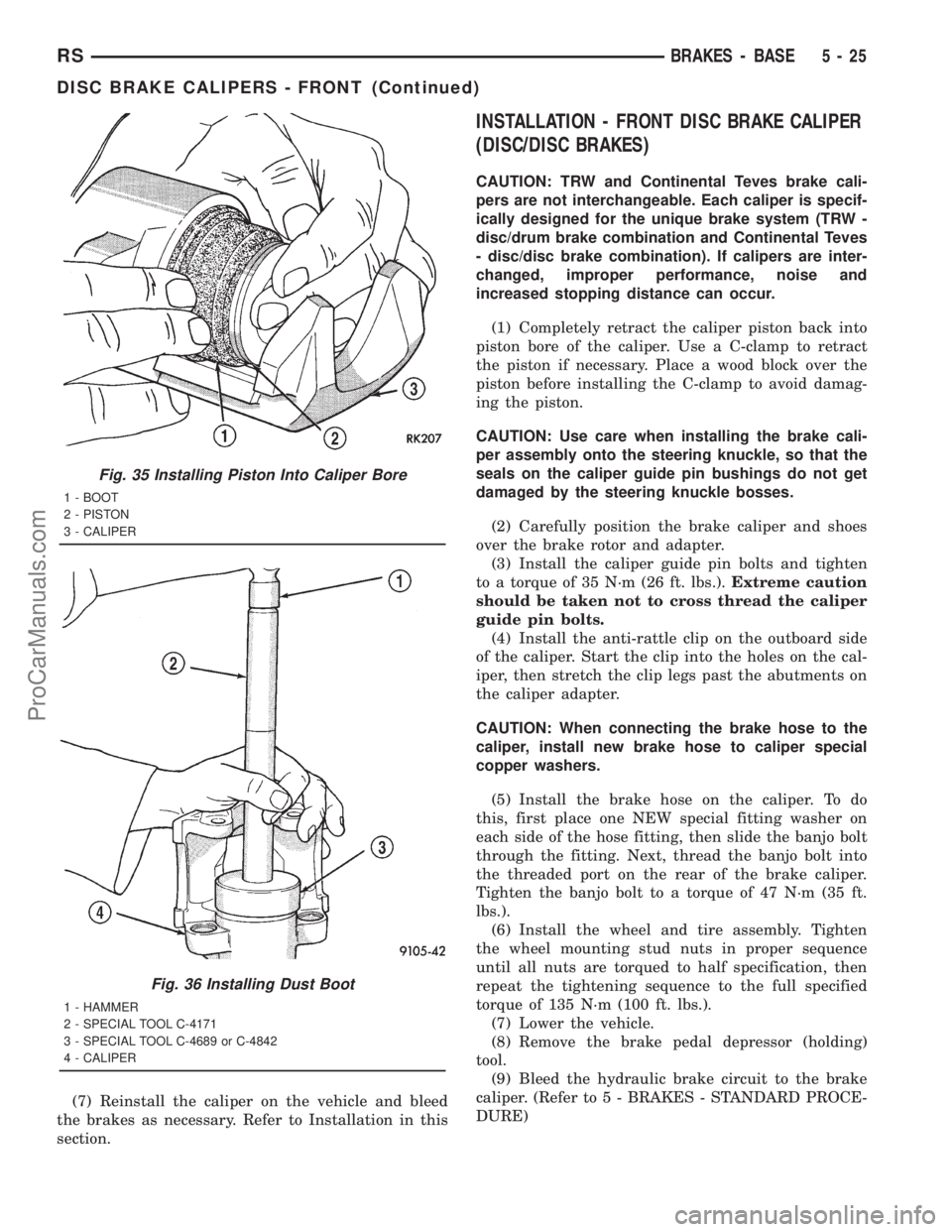
Fig. 35 Installing Piston Into Caliper Bore
1 - BOOT
2 - PISTON
3 - CALIPER
Fig. 36 Installing Dust Boot
1 - HAMMER
2 - SPECIAL TOOL C-4171
3 - SPECIAL TOOL C-4689 or C-4842
4 - CALIPER
RSBRAKES - BASE5-25
DISC BRAKE CALIPERS - FRONT (Continued)
ProCarManuals.com
Page 185 of 2321
(10) Road test the vehicle and make several stops
to wear off any foreign material on the brakes and to
seat the brake shoe linings.
INSTALLATION - FRONT DISC BRAKE CALIPER
(DISC/DRUM BRAKES)
CAUTION: TRW and Continental Teves brake cali-
pers are not interchangeable. Each caliper is specif-
ically designed for the unique brake system (TRW -
disc/drum brake combination and Continental Teves
- disc/disc brake combination). If calipers are inter-
changed, improper performance, noise and
increased stopping distance can occur.
(1) Completely retract the caliper piston back into
the bore of the caliper. Use a C-clamp to retract the
piston if necessary. Place a wood block over the pis-
ton before installing the C-clamp to avoid damaging
the piston.
CAUTION: Use care when installing the caliper onto
the disc brake adapter to avoid damaging the boots
on the caliper guide pins.
(2) Install the disc brake caliper over the brake
shoes on the brake caliper adapter.
(3) Align the caliper guide pin bolt holes with the
guide pins. Install the caliper guide pin bolts and
tighten them to a torque of 35 N´m (26 ft. lbs.) (Fig.
32).
(4) Install the banjo bolt connecting the brake hose
to the brake caliper (Fig. 32). Install NEW copper
washers on each side of the hose fitting as the banjo
bolt is guided through the fitting. Thread the banjo
bolt into the caliper and tighten it to a torque of 47
N´m (35 ft. lbs.).
(5) Install the tire and wheel assembly. Tighten
the wheel mounting nuts to a torque of 135 N´m (100
ft. lbs.).
(6) Lower the vehicle.
(7) Remove the brake pedal holding tool.
(8) Bleed the caliper as necessary. (Refer to 5 -
BRAKES - BASE - STANDARD PROCEDURE).
(9) Road test the vehicle and make several stops to
wear off any foreign material on the brakes and to
seat the brake shoes.
DISC BRAKE CALIPERS -
REAR
REMOVAL - REAR DISC BRAKE CALIPER
NOTE: Handling of the rotor and caliper, must be
done in such a way as to avoid damage to the rotorand scratching or nicking of lining on the brake
shoes.
(1) Depress the brake pedal past its first inch of
travel and hold it in this position using a brake pedal
depressor (holding) tool. This is done to isolate the
master cylinder from the brake hydraulic system dis-
allowing the brake fluid to completely drain out of
the brake fluid reservoir.
(2) Raise the vehicle. (Refer to LUBRICATION &
MAINTENANCE/HOISTING - STANDARD PROCE-
DURE)
(3) Remove rear wheel and tire assembly from
vehicle.
(4) Remove the banjo bolt connecting the brake
hose to the brake caliper. There are two washers (one
on each side of the brake hose fitting) that will come
off with the banjo bolt. Discard these washers.
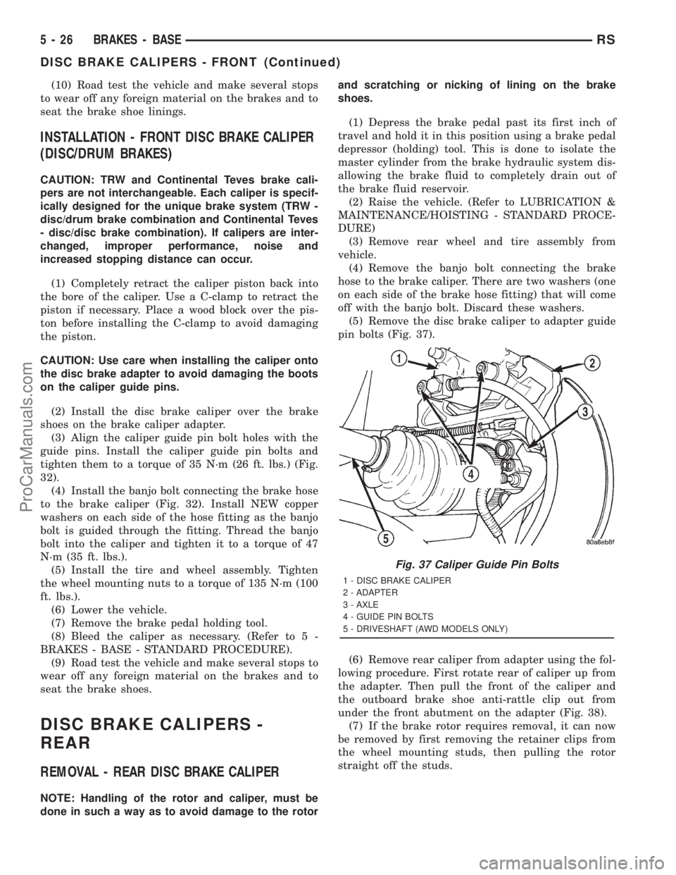
(5) Remove the disc brake caliper to adapter guide
pin bolts (Fig. 37).
(6) Remove rear caliper from adapter using the fol-
lowing procedure. First rotate rear of caliper up from
the adapter. Then pull the front of the caliper and
the outboard brake shoe anti-rattle clip out from
under the front abutment on the adapter (Fig. 38).
(7) If the brake rotor requires removal, it can now
be removed by first removing the retainer clips from
the wheel mounting studs, then pulling the rotor
straight off the studs.
Fig. 37 Caliper Guide Pin Bolts
1 - DISC BRAKE CALIPER
2 - ADAPTER
3 - AXLE
4 - GUIDE PIN BOLTS
5 - DRIVESHAFT (AWD MODELS ONLY)
5 - 26 BRAKES - BASERS
DISC BRAKE CALIPERS - FRONT (Continued)
ProCarManuals.com
Page 201 of 2321
OPERATION - PROPORTIONING VALVE
(HEIGHT SENSING)
Vehicles not equipped with ABS use a height sens-
ing proportioning valve.
The height sensing proportioning valve operates
similarly to a standard proportioning valve in the fol-
lowing way. As hydraulic pressure is applied to the
valve, full input hydraulic pressure is supplied to the
rear brakes up to a certain pressure point, called the
split point. Beyond the split point, the proportioning
valve reduces the amount of hydraulic pressure to
the rear brakes according to a given ratio. Thus, on
light brake applications, approximately equal
hydraulic pressure will be transmitted to both the
front and rear brakes. Upon heavier brake applica-
tions, the hydraulic pressure transmitted to the rear
brakes will be lower than the front brakes. This will
prevent premature rear wheel lockup and skid.
Here is how the height sensing proportioning valve
differs from a standard proportioning valve. As the
height of the rear suspension changes, the height
sensing portion of the proportioning valve changes
the split point of the proportioning valve. When the
height of the rear suspension is low, the proportion-
ing valve interprets this as extra load and the split
point of the proportioning valve is raised to a higher
pressure to allow for more rear braking. When the
height of the rear suspension is high, the proportion-
ing valve interprets this as a light load and the split
point of the proportioning valve is lowered to a lower
pressure and rear braking is reduced.
The height sensing proportioning valve regulates
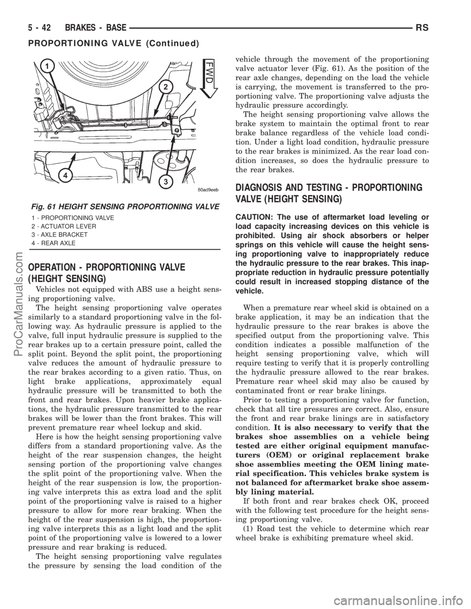
the pressure by sensing the load condition of thevehicle through the movement of the proportioning
valve actuator lever (Fig. 61). As the position of the
rear axle changes, depending on the load the vehicle
is carrying, the movement is transferred to the pro-
portioning valve. The proportioning valve adjusts the
hydraulic pressure accordingly.
The height sensing proportioning valve allows the
brake system to maintain the optimal front to rear
brake balance regardless of the vehicle load condi-
tion. Under a light load condition, hydraulic pressure
to the rear brakes is minimized. As the rear load con-
dition increases, so does the hydraulic pressure to
the rear brakes.
DIAGNOSIS AND TESTING - PROPORTIONING
VALVE (HEIGHT SENSING)
CAUTION: The use of aftermarket load leveling or
load capacity increasing devices on this vehicle is
prohibited. Using air shock absorbers or helper
springs on this vehicle will cause the height sens-
ing proportioning valve to inappropriately reduce
the hydraulic pressure to the rear brakes. This inap-
propriate reduction in hydraulic pressure potentially
could result in increased stopping distance of the
vehicle.
When a premature rear wheel skid is obtained on a
brake application, it may be an indication that the
hydraulic pressure to the rear brakes is above the
specified output from the proportioning valve. This
condition indicates a possible malfunction of the
height sensing proportioning valve, which will
require testing to verify that it is properly controlling
the hydraulic pressure allowed to the rear brakes.
Premature rear wheel skid may also be caused by
contaminated front or rear brake linings.
Prior to testing a proportioning valve for function,
check that all tire pressures are correct. Also, ensure
the front and rear brake linings are in satisfactory
condition.It is also necessary to verify that the
brakes shoe assemblies on a vehicle being
tested are either original equipment manufac-
turers (OEM) or original replacement brake
shoe assemblies meeting the OEM lining mate-
rial specification. This vehicles brake system is
not balanced for aftermarket brake shoe assem-
bly lining material.
If both front and rear brakes check OK, proceed
with the following test procedure for the height sens-
ing proportioning valve.
(1) Road test the vehicle to determine which rear
wheel brake is exhibiting premature wheel skid.
Fig. 61 HEIGHT SENSING PROPORTIONING VALVE
1 - PROPORTIONING VALVE
2 - ACTUATOR LEVER
3 - AXLE BRACKET
4 - REAR AXLE
5 - 42 BRAKES - BASERS
PROPORTIONING VALVE (Continued)
ProCarManuals.com
Page 338 of 2321
AUDIO
TABLE OF CONTENTS
page page
AUDIO
DESCRIPTION............................1
OPERATION.............................1
DIAGNOSIS AND TESTING..................1
ANTENNA BODY & CABLE
DESCRIPTION............................3
OPERATION.............................3
DIAGNOSIS AND TESTING..................3
REMOVAL...............................4
INSTALLATION............................4
CD CHANGER
DESCRIPTION............................6
OPERATION.............................6
REMOVAL...............................6
INSTALLATION............................6
CHOKE
DIAGNOSIS AND TESTING..................6
D-PILLAR SPEAKER
REMOVAL...............................6
INSTALLATION............................7
DASH PANEL SPEAKER
REMOVAL...............................7INSTALLATION............................7
DOOR MOUNTED SPEAKER
REMOVAL...............................7
INSTALLATION............................7
QUARTER PANEL SPEAKER
REMOVAL...............................8
INSTALLATION............................8
RADIO
DIAGNOSIS AND TESTING..................8
REMOVAL...............................9
INSTALLATION............................9
RADIO NOISE SUPPRESSION COMPONENTS
DESCRIPTION............................9
OPERATION.............................9
REMOTE SWITCHES
DESCRIPTION...........................10
OPERATION.............................10
DIAGNOSIS AND TESTING.................11
REMOVAL..............................11
INSTALLATION...........................12
AUDIO
DESCRIPTION
There are four different system combinations avail-
able on the RS models. The available radio options
are:
²AM/FM Cassette
²AM/FM Compact Disc with Compact Disc
Changer
²AM/FM Cassette with single Compact Disc
Player
²AM/FM Cassette with Compact Disc Changer
All factory installed radio receivers are stereo Elec-
tronically Tuned Radios (ETR) and include and elec-
tronic digital clock function.
OPERATION
Operating instructions for the factory installed
audio systems can be found in the Owner's Manual
provided with this vehicle.
DIAGNOSIS AND TESTING
WARNING:
ON VEHICLES EQUIPPED WITH AIRBAGS, REFER
TO ELECTRICAL, RESTRAINTS BEFORE ATTEMPT-
ING ANY STEERING WHEEL, STEERING COLUMN,
OR INSTRUMENT PANEL COMPONENT DIAGNOSIS
OR SERVICE. FAILURE TO TAKE THE PROPER
PRECAUTIONS COULD RESULT IN ACCIDENTAL
AIRBAG DEPLOYMENT AND POSSIBLE PERSONAL
INJURY.
RSAUDIO8A-1
ProCarManuals.com
Page 340 of 2321
CONDITION POSSIBLE CAUSE CORRECTION
4. POOR ANTENNA
CONNECTION AT
RADIO OR IN LINE.4. SEAT CONNECTOR.
NO/POOR TAPE
OPERATION.1. FAULTY TAPE. 1. INSERT KNOWN GOOD TAPE AND TEST OPERATION.
2. FOREIGN OBJECTS
BEHIND TAPE DOOR.2. REMOVE FOREIGN OBJECTS AND TEST OPERATION.
3. DIRTY CASSETTE
TAPE HEAD.3. CLEAN HEAD WITH MOPAR CASSETTE HEAD CLEANER.
4. FAULTY TAPE DECK. 4. EXCHANGE OR REPLACE RADIO, IF REQUIRED.
NO COMPACT
DISC
OPERATION1. FAULTY CD. 1. INSERT KNOWN GOOD CD AND TEST OPERATION.
2. FOREIGN MATERIAL
ON CD.2. CLEAN CD AND TEST OPERATION.
3. CONDENSATION ON
CD OR OPTICS.3. ALLOW TEMPERATURE OF VEHICLE INTERIOR TO
STABILIZE AND TEST OPERATION.
4. FAULTY CD PLAYER. 4. EXCHANGE OR REPLACE RADIO, IF REQUIRED.
ANTENNA BODY & CABLE
DESCRIPTION
All models use a fixed-length stainless steel rod-
type antenna mast, installed at the right front fender
of the vehicle. The antenna mast is connected to the
center wire of the coaxial antenna cable, and is not
grounded to any part of the vehicle.
OPERATION
To minimize static, the antenna base must have a
good ground. The coaxial antenna cable shield (the
outer wire mesh of the cable) is grounded to the
antenna base and the radio chassis.
The antenna coaxial cable has an additional dis-
connect, located near the right end of the instrument
panel. This additional disconnect allows the instru-
ment panel assembly to be removed and installed
without removing the radio.
The factory-installed Electronically Tuned Radios
(ETRs) automatically compensate for radio antenna
trim. Therefore, no antenna trimmer adjustment is
required or possible when replacing the receiver or
the antenna.
DIAGNOSIS AND TESTING
WARNING:
ON VEHICLES EQUIPPED WITH AIRBAGS, REFER
TO ELECTRICAL, RESTRAINTS BEFORE ATTEMPT-ING ANY STEERING WHEEL, STEERING COLUMN,
OR INSTRUMENT PANEL COMPONENT DIAGNOSIS
OR SERVICE. FAILURE TO TAKE THE PROPER
PRECAUTIONS COULD RESULT IN ACCIDENTAL
AIRBAG DEPLOYMENT AND POSSIBLE PERSONAL
INJURY.
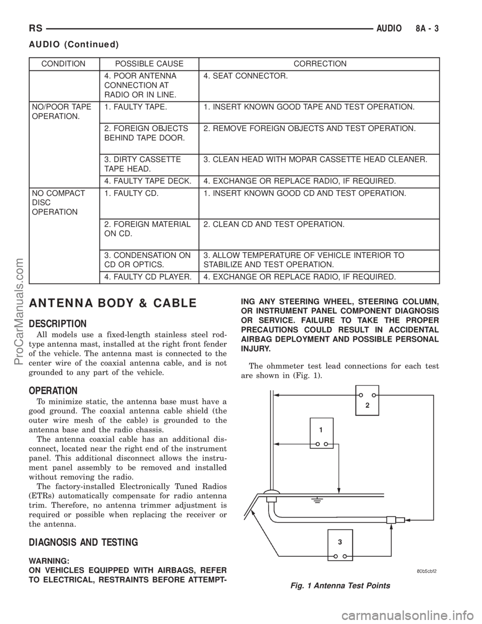
The ohmmeter test lead connections for each test
are shown in (Fig. 1).
Fig. 1 Antenna Test Points
RSAUDIO8A-3
AUDIO (Continued)
ProCarManuals.com
Page 345 of 2321
(4) Connect battery negative cable.
QUARTER PANEL SPEAKER
REMOVAL
(1) Disconnect and isolate the battery negative
cable.
(2) Remove speaker grill by prying away from trim
panel.
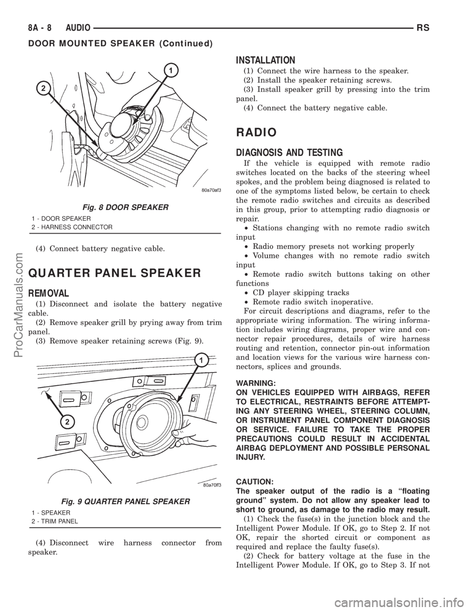
(3) Remove speaker retaining screws (Fig. 9).
(4) Disconnect wire harness connector from
speaker.
INSTALLATION
(1) Connect the wire harness to the speaker.
(2) Install the speaker retaining screws.
(3) Install speaker grill by pressing into the trim
panel.
(4) Connect the battery negative cable.
RADIO
DIAGNOSIS AND TESTING
If the vehicle is equipped with remote radio
switches located on the backs of the steering wheel
spokes, and the problem being diagnosed is related to
one of the symptoms listed below, be certain to check
the remote radio switches and circuits as described
in this group, prior to attempting radio diagnosis or
repair.
²Stations changing with no remote radio switch
input
²Radio memory presets not working properly
²Volume changes with no remote radio switch
input
²Remote radio switch buttons taking on other
functions
²CD player skipping tracks
²Remote radio switch inoperative.
For circuit descriptions and diagrams, refer to the
appropriate wiring information. The wiring informa-
tion includes wiring diagrams, proper wire and con-
nector repair procedures, details of wire harness
routing and retention, connector pin-out information
and location views for the various wire harness con-
nectors, splices and grounds.
WARNING:
ON VEHICLES EQUIPPED WITH AIRBAGS, REFER
TO ELECTRICAL, RESTRAINTS BEFORE ATTEMPT-
ING ANY STEERING WHEEL, STEERING COLUMN,
OR INSTRUMENT PANEL COMPONENT DIAGNOSIS
OR SERVICE. FAILURE TO TAKE THE PROPER
PRECAUTIONS COULD RESULT IN ACCIDENTAL
AIRBAG DEPLOYMENT AND POSSIBLE PERSONAL
INJURY.
CAUTION:
The speaker output of the radio is a ªfloating
groundº system. Do not allow any speaker lead to
short to ground, as damage to the radio may result.
(1) Check the fuse(s) in the junction block and the
Intelligent Power Module. If OK, go to Step 2. If not
OK, repair the shorted circuit or component as
required and replace the faulty fuse(s).
(2) Check for battery voltage at the fuse in the
Intelligent Power Module. If OK, go to Step 3. If not
Fig. 8 DOOR SPEAKER
1 - DOOR SPEAKER
2 - HARNESS CONNECTOR
Fig. 9 QUARTER PANEL SPEAKER
1 - SPEAKER
2 - TRIM PANEL
8A - 8 AUDIORS
DOOR MOUNTED SPEAKER (Continued)
ProCarManuals.com