2001 DODGE TOWN AND COUNTRY battery replacement
[x] Cancel search: battery replacementPage 552 of 2321
POWER LOCKS
TABLE OF CONTENTS
page page
POWER LOCKS
DESCRIPTION...........................39
OPERATION.............................40
DOOR LOCK MOTOR
DIAGNOSIS AND TESTING.................41
DOOR LOCK MOTOR....................41
DOOR LOCK SWITCH
DESCRIPTION...........................41
DIAGNOSIS AND TESTING.................41
DOOR LOCK SWITCH...................41
REMOVAL..............................42
INSTALLATION...........................42
KEYLESS ENTRY TRANSMITTER
STANDARD PROCEDURE..................42
HORN CHIRP PREFERENCE..............42BATTERY REPLACEMENT................42
SPECIFICATIONS........................42
REMOTE KEYLESS ENTRY MODULE
DESCRIPTION...........................43
OPERATION.............................43
DIAGNOSIS AND TESTING.................43
REMOTE KEYLESS ENTRY...............43
STANDARD PROCEDURE..................43
PROGRAMMING RKE MODULE............43
REMOVAL..............................43
INSTALLATION...........................44
SLIDING DOOR LOCK MOTOR
REMOVAL..............................44
INSTALLATION...........................44
POWER LOCKS
DESCRIPTION
POWER DOOR LOCK SYSTEM
The front doors, sliding door(s) and liftgate are
equipped with actuator motors to lock or unlock the
latch mechanisms. The door lock actuator motor is
not serviced separately from the door latch, except
for the sliding door(s).
AUTOMATIC DOOR LOCKS
The vehicle comes with two options for power door
locks:
²Rolling automatic lock (ENABLE), doors auto-
matically lock at approximately at 25.7 Km/h (16
mph).
²No rolling automatic lock (DISABLE), doors do
not automatically lock when the vehicle is moving.
DOOR LOCK INHIBIT
The BCM cancels out the door lock switch actua-
tion, when the key is in the Ignition Switch and
either front door is open.
Pressing the key fob RKE lock/unlock under these
conditions results in normal lock/unlock activation.
CENTRAL LOCKING
If equipped with Vehicle Theft Security System
(VTSS), all the doors can be locked with the key by
using any of the door lock cylinders. Turning the key
to the lock position will lock all the doors. If a sliding
door is open when this is done, the sliding door will
lock when it is closed.
DOOR LOCK CIRCUIT PROTECTION
The door lock system is protected by a 40 amp fuse
located in the IPM. The BCM receives lock/unlock
input and will turn on the appropriate drivers and
provide a voltage level to the door lock motor for a
specific time. The IPM is located along the side of the
vehicle battery in the engine compartment.
RSPOWER LOCKS8N-39
ProCarManuals.com
Page 555 of 2321
REMOVAL
(1) Disconnect and isolate the battery negative
cable.
(2) Remove door trim panel. Refer to Body, Door -
Front, Trim Panel, Removal.
(3) Disconnect wire connector from back of door
lock switch.
(4) Remove two screws to door lock switch.
(5) Remove switch from vehicle.
INSTALLATION
(1) Install the switch into the vehicle.
(2) Install the two screws to door lock switch.
(3) Connect wire connector to back of door lock
switch.
(4) Install door trim panel. Refer to Body, Door -
Front, Trim Panel, Installation.
(5) Connect the battery negative cable.
KEYLESS ENTRY
TRANSMITTER
STANDARD PROCEDURE - HORN CHIRP
PREFERENCE
DISABLING
The horn chirp can be toggled using a DRB IIItor
by using the Remote Keyless Entry (RKE) transmit-
ter.
To DISABLE (cancelling) the horn chirp feature,
press and hold the transmitter LOCK button for a
minimum of four seconds. While pressing the LOCK
button in, press the UNLOCK button. The horn chirp
feature will not function until the above procedure is
repeated.
ENABLING
The horn chirp can be toggled using a DRB IIItor
by using the Remote Keyless Entry (RKE) transmit-
ter.
To ENABLE (reinstate) the horn chirp feature, use
any one of the four key fob transmitters and reverse
the above procedures. It will ENABLE the horn chirp
feature for all transmitters.
STANDARD PROCEDURE - BATTERY
REPLACEMENT
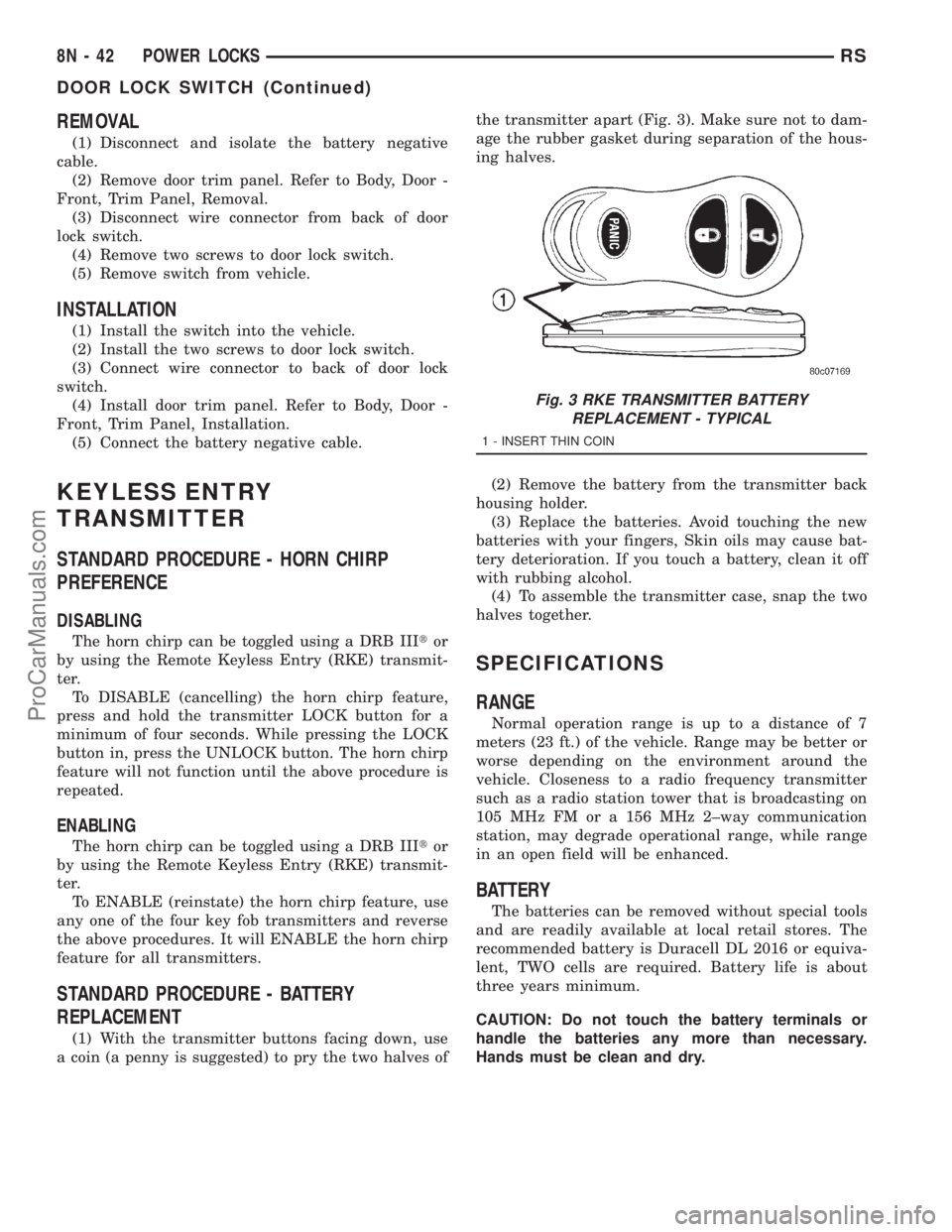
(1) With the transmitter buttons facing down, use
a coin (a penny is suggested) to pry the two halves ofthe transmitter apart (Fig. 3). Make sure not to dam-
age the rubber gasket during separation of the hous-
ing halves.
(2) Remove the battery from the transmitter back
housing holder.
(3) Replace the batteries. Avoid touching the new
batteries with your fingers, Skin oils may cause bat-
tery deterioration. If you touch a battery, clean it off
with rubbing alcohol.
(4) To assemble the transmitter case, snap the two
halves together.
SPECIFICATIONS
RANGE
Normal operation range is up to a distance of 7
meters (23 ft.) of the vehicle. Range may be better or
worse depending on the environment around the
vehicle. Closeness to a radio frequency transmitter
such as a radio station tower that is broadcasting on
105 MHz FM or a 156 MHz 2±way communication
station, may degrade operational range, while range
in an open field will be enhanced.
BATTERY
The batteries can be removed without special tools
and are readily available at local retail stores. The
recommended battery is Duracell DL 2016 or equiva-
lent, TWO cells are required. Battery life is about
three years minimum.
CAUTION: Do not touch the battery terminals or
handle the batteries any more than necessary.
Hands must be clean and dry.
Fig. 3 RKE TRANSMITTER BATTERY
REPLACEMENT - TYPICAL
1 - INSERT THIN COIN
8N - 42 POWER LOCKSRS
DOOR LOCK SWITCH (Continued)
ProCarManuals.com
Page 575 of 2321
INSTALLATION
(1) Obtain new vent window motor.
(2) Snap the actuator link socket onto the quarter
window ball socket. Using a soft rubber mallet, push
the circular link tab flush with link surface.
(3) Install bolts holding power vent motor to D-pil-
lar.
(4) Reconnect wire connector to power vent motor.
(5) Reconnect the battery negative cable.
(6) Cycle quarter window open/close to verify func-
tion.
(7) Install D-pillar trim panel.
WINDOW MOTOR
REMOVAL
The window motor is incorporated into the window
regulator assembly. If the window motor requires
replacement, the window regulator must be replaced.
(Refer to 23 - BODY/DOOR - FRONT/WINDOW
REGULATOR - REMOVAL).
WINDOW SWITCH
DIAGNOSIS AND TESTING - WINDOW SWITCH
(1) Remove the desired switch to be tested from
the door trim panel. Driver's side (master) or passen-
ger side. (Refer to 8 - ELECTRICAL/POWER WIN-
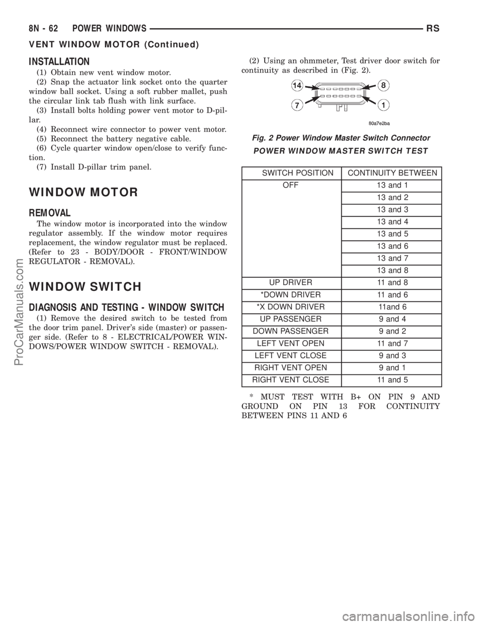
DOWS/POWER WINDOW SWITCH - REMOVAL).(2) Using an ohmmeter, Test driver door switch for
continuity as described in (Fig. 2).
POWER WINDOW MASTER SWITCH TEST
SWITCH POSITION CONTINUITY BETWEEN
OFF 13 and 1
13 and 2
13 and 3
13 and 4
13 and 5
13 and 6
13 and 7
13 and 8
UP DRIVER 11 and 8
*DOWN DRIVER 11 and 6
*X DOWN DRIVER 11and 6
UP PASSENGER 9 and 4
DOWN PASSENGER 9 and 2
LEFT VENT OPEN 11 and 7
LEFT VENT CLOSE 9 and 3
RIGHT VENT OPEN 9 and 1
RIGHT VENT CLOSE 11 and 5
* MUST TEST WITH B+ ON PIN 9 AND
GROUND ON PIN 13 FOR CONTINUITY
BETWEEN PINS 11 AND 6
Fig. 2 Power Window Master Switch Connector
8N - 62 POWER WINDOWSRS
VENT WINDOW MOTOR (Continued)
ProCarManuals.com
Page 581 of 2321
RESTRAINTS
DESCRIPTION - SIDE IMPACT AIRBAG
SYSTEM
Vehicles equipped with the Side Impact Airbag
System utilize two airbags mounted to each front
seat back frame. This system is designed to protect
occupants in the event of a side impact collision. The
individual seat airbags are not serviceable. If
deployed or defective, the entire seat back assembly
must be replaced.
OPERATION - SIDE IMPACT AIRBAG SYSTEM
The Side Impact Airbag Control Module (SIACM)
controls the seat back mounted airbags. If the
SIACM determines the impact is severe enough, the
appropriate airbag will inflate, tearing open the front
seat back trim cover protecting the passengers. Once
a seat back mounted airbag has been deployed, the
complete seat back assembly and all damaged parts
must be replaced.
WARNINGS
WARNING: THIS SYSTEM IS A SENSITIVE, COM-
PLEX ELECTRO±MECHANICAL UNIT. DISCONNECT
AND ISOLATE THE BATTERY NEGATIVE CABLE
BEFORE BEGINNING AIRBAG SYSTEM COMPO-
NENT REMOVAL OR INSTALLATION PROCEDURES.
THIS WILL DISABLE THE AIRBAG SYSTEM. FAIL-
URE TO DISCONNECT THE BATTERY COULD
RESULT IN ACCIDENTAL AIRBAG DEPLOYMENT
AND POSSIBLE PERSONAL INJURY.
ALLOW SYSTEM CAPACITOR TO DISCHARGE FOR
TWO MINUTES BEFORE REMOVING AIRBAG COM-
PONENTS.
DO NOT PLACE AN INTACT UNDEPLOYED AIRBAG
FACE DOWN ON A SOLID SURFACE, THE AIRBAG
WILL PROPEL INTO THE AIR IF ACCIDENTALLY
DEPLOYED AND COULD RESULT IN PERSONAL
INJURY. WHEN CARRYING OR HANDLING AN
UNDEPLOYED AIRBAG MODULE, THE TRIM SIDEOF THE AIRBAG SHOULD BE POINTING AWAY
FROM THE BODY TO MINIMIZE POSSIBILITY OF
INJURY IF ACCIDENTAL DEPLOYMENT OCCURS.
REPLACE AIRBAG SYSTEM COMPONENTS WITH
MOPARž REPLACEMENT PARTS. SUBSTITUTE
PARTS MAY APPEAR INTERCHANGEABLE, BUT
INTERNAL DIFFERENCES MAY RESULT IN INFE-
RIOR OCCUPANT PROTECTION.
WEAR SAFETY GLASSES, RUBBER GLOVES, AND
LONG SLEEVED CLOTHING WHEN CLEANING
POWDER RESIDUE FROM VEHICLE AFTER AIRBAG
DEPLOYMENT. SODIUM HYDROXIDE POWDER
RESIDUE EMITTED FROM A DEPLOYED AIRBAG
CAN CAUSE SKIN IRRITATION. FLUSH AFFECTED
AREA WITH COOL WATER IF IRRITATION IS EXPE-
RIENCED. IF NASAL OR THROAT IRRITATION IS
EXPERIENCED, EXIT THE VEHICLE FOR FRESH AIR
UNTIL THE IRRITATION CEASES. IF IRRITATION
CONTINUES, SEE A PHYSICIAN.
DO NOT USE A REPLACEMENT AIRBAG THAT IS
NOT IN THE ORIGINAL PACKAGING, IMPROPER
DEPLOYMENT AND PERSONAL INJURY CAN
RESULT.
THE FACTORY INSTALLED FASTENERS, SCREWS
AND BOLTS USED TO FASTEN AIRBAG COMPO-
NENTS HAVE A SPECIAL COATING AND ARE SPE-
CIFICALLY DESIGNED FOR THE AIRBAG SYSTEM.
DO NOT USE SUBSTITUTE FASTENERS, USE ONLY
ORIGINAL EQUIPMENT FASTENERS LISTED IN THE
PARTS CATALOG WHEN FASTENER REPLACE-
MENT IS REQUIRED.
CAUTION:
Deployed Front Air Bags may or may not have live
pyrotechnic material within the air bag inflator. Do
not dispose of 2001 Model Year Driver and Passen-
ger Airbags unless you are sure of complete
deployment. Please refer to the Hazardous Sub-
stance Control System for Proper Disposal. Dispose
of deployed air bags in a manner consistent with
state, provincial, local, and federal regulations.
8O - 2 RESTRAINTSRS
ProCarManuals.com
Page 599 of 2321
INSTALLATION
(1) Slide cable into throttle cable bracket and
engage retaining tabs.
(2) Rotate the throttle cam forward to the wide
open position and install speed control cable clasp.
(3) Rotate the throttle cam forward to the wide
open position and install throttle cable clasp.
(4) Install retaining clip that attaches cable to
servo.
(5) Insert servo studs through holes in the mount-
ing bracket and speed control cable.
(6) Install nuts, tighten to 6.7 N´m (60 in. lbs.).
(7) Connect vacuum hose to servo.
(8) Connect electrical connector.
(9) Install servo and bracket and tighten nuts and
bolt.
(10) Connect negative battery cable.
SERVO
DESCRIPTION
The servo unit consists of a solenoid valve body,
and a vacuum chamber. The solenoid valve body con-
tains three solenoids:
²Vacuum
²Vent
²Dump
The vacuum chamber contains a diaphragm with a
cable attached to control the throttle linkage.
OPERATION
The PCM controls the solenoid valve body. The
solenoid valve body controls the application and
release of vacuum to the diaphragm of the vacuum
servo. The servo unit cannot be repaired and is ser-
viced only as a complete assembly.
Power is supplied to the servo by the PCM through
the brake switch. The PCM controls the ground path
for the vacuum and vent solenoids.
The dump solenoid is energized anytime it receives
power. If power to the dump solenoid is interrupted,
the solenoid dumps vacuum in the servo. This pro-
vides a safety backup to the vent and vacuum sole-
noids.
The vacuum and vent solenoids must be grounded
at the PCM to operate. When the PCM grounds the
vacuum servo solenoid, the solenoid allows vacuum
to enter the servo and pull open the throttle plate
using the cable. When the PCM breaks the ground,
the solenoid closes and no more vacuum is allowed to
enter the servo. The PCM also operates the vent sole-
noid via ground. The vent solenoid opens and closes a
passage to bleed or hold vacuum in the servo as
required.The PCM duty cycles the vacuum and vent sole-
noids to maintain the set speed, or to accelerate and
decelerate the vehicle. To increase throttle opening,
the PCM grounds the vacuum and vent solenoids. To
decrease throttle opening, the PCM removes the
grounds from the vacuum and vent solenoids.
REMOVAL
(1) Release hood latch and open hood.
(2) Disconnect the negative battery cable.
(3) Disconnect the throttle and speed control cable
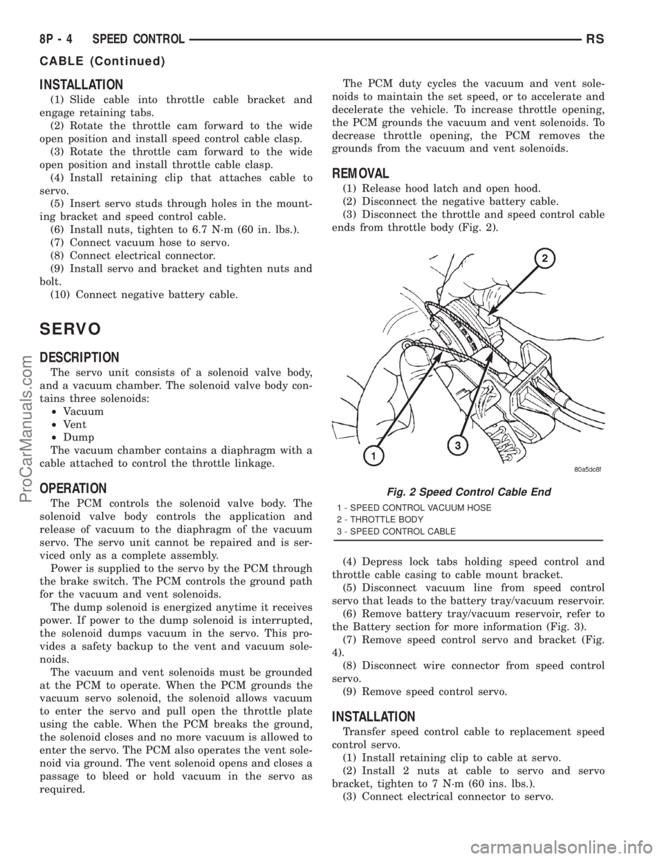
ends from throttle body (Fig. 2).
(4) Depress lock tabs holding speed control and
throttle cable casing to cable mount bracket.
(5) Disconnect vacuum line from speed control
servo that leads to the battery tray/vacuum reservoir.
(6) Remove battery tray/vacuum reservoir, refer to
the Battery section for more information (Fig. 3).
(7) Remove speed control servo and bracket (Fig.
4).
(8) Disconnect wire connector from speed control
servo.
(9) Remove speed control servo.
INSTALLATION
Transfer speed control cable to replacement speed
control servo.
(1) Install retaining clip to cable at servo.
(2) Install 2 nuts at cable to servo and servo
bracket, tighten to 7 N´m (60 ins. lbs.).
(3) Connect electrical connector to servo.
Fig. 2 Speed Control Cable End
1 - SPEED CONTROL VACUUM HOSE
2 - THROTTLE BODY
3 - SPEED CONTROL CABLE
8P - 4 SPEED CONTROLRS
CABLE (Continued)
ProCarManuals.com
Page 1260 of 2321
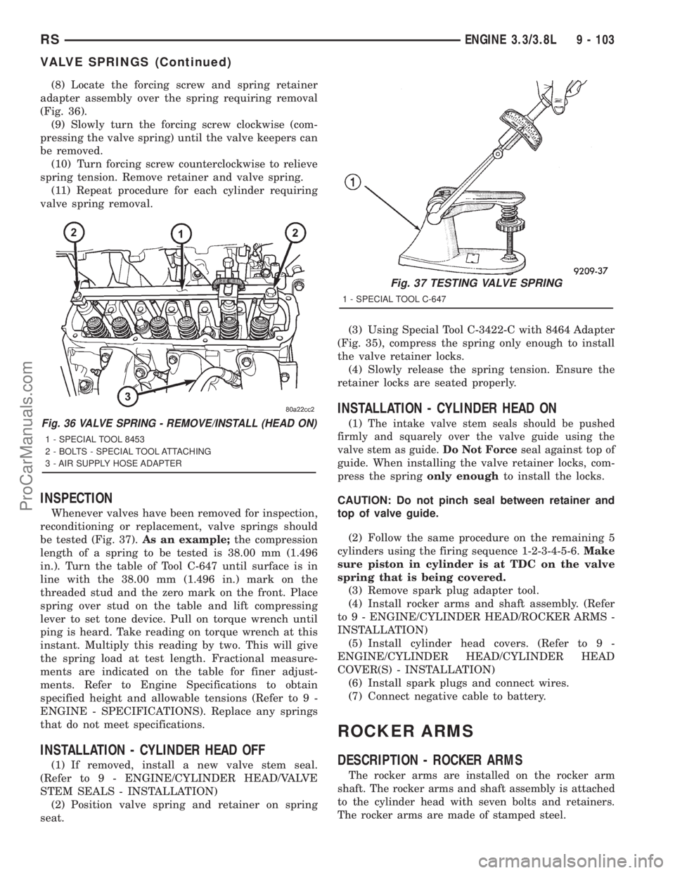
(8) Locate the forcing screw and spring retainer
adapter assembly over the spring requiring removal
(Fig. 36).
(9) Slowly turn the forcing screw clockwise (com-
pressing the valve spring) until the valve keepers can
be removed.
(10) Turn forcing screw counterclockwise to relieve
spring tension. Remove retainer and valve spring.
(11) Repeat procedure for each cylinder requiring
valve spring removal.
INSPECTION
Whenever valves have been removed for inspection,
reconditioning or replacement, valve springs should
be tested (Fig. 37).As an example;the compression
length of a spring to be tested is 38.00 mm (1.496
in.). Turn the table of Tool C-647 until surface is in
line with the 38.00 mm (1.496 in.) mark on the
threaded stud and the zero mark on the front. Place
spring over stud on the table and lift compressing
lever to set tone device. Pull on torque wrench until
ping is heard. Take reading on torque wrench at this
instant. Multiply this reading by two. This will give
the spring load at test length. Fractional measure-
ments are indicated on the table for finer adjust-
ments. Refer to Engine Specifications to obtain
specified height and allowable tensions (Refer to 9 -
ENGINE - SPECIFICATIONS). Replace any springs
that do not meet specifications.
INSTALLATION - CYLINDER HEAD OFF
(1) If removed, install a new valve stem seal.
(Refer to 9 - ENGINE/CYLINDER HEAD/VALVE
STEM SEALS - INSTALLATION)
(2) Position valve spring and retainer on spring
seat.(3) Using Special Tool C-3422-C with 8464 Adapter
(Fig. 35), compress the spring only enough to install
the valve retainer locks.
(4) Slowly release the spring tension. Ensure the
retainer locks are seated properly.
INSTALLATION - CYLINDER HEAD ON
(1)The intake valve stem seals should be pushed
firmly and squarely over the valve guide using the
valve stem as guide.Do Not Force
seal against top of
guide. When installing the valve retainer locks, com-
press the springonly enoughto install the locks.
CAUTION: Do not pinch seal between retainer and
top of valve guide.
(2) Follow the same procedure on the remaining 5
cylinders using the firing sequence 1-2-3-4-5-6.Make
sure piston in cylinder is at TDC on the valve
spring that is being covered.
(3) Remove spark plug adapter tool.
(4) Install rocker arms and shaft assembly. (Refer
to 9 - ENGINE/CYLINDER HEAD/ROCKER ARMS -
INSTALLATION)
(5) Install cylinder head covers. (Refer to 9 -
ENGINE/CYLINDER HEAD/CYLINDER HEAD
COVER(S) - INSTALLATION)
(6) Install spark plugs and connect wires.
(7) Connect negative cable to battery.
ROCKER ARMS
DESCRIPTION - ROCKER ARMS
The rocker arms are installed on the rocker arm
shaft. The rocker arms and shaft assembly is attached
to the cylinder head with seven bolts and retainers.
The rocker arms are made of stamped steel.
Fig. 36 VALVE SPRING - REMOVE/INSTALL (HEAD ON)
1 - SPECIAL TOOL 8453
2 - BOLTS - SPECIAL TOOL ATTACHING
3 - AIR SUPPLY HOSE ADAPTER
Fig. 37 TESTING VALVE SPRING
1 - SPECIAL TOOL C-647
RSENGINE 3.3/3.8L9 - 103
VALVE SPRINGS (Continued)
ProCarManuals.com
Page 1403 of 2321
²Needle Nose Pliers ± For Removal Of Thread
Insert Driving Tang
REMOVAL
The front cradle crossmember must be installed in
the design location to achieve proper front end sus-
pension alignment. If the cradle crossmember is
removed without applying reference marks on the
frame rails, align the cradle crossmember according
to the dimensions provided in this group.
NOTE: If the caged nuts in the frame rails become
damaged and cannot be reused, a replacement nut
can be obtained through MoparT.
REMOVAL
(1) Disconnect battery negative cable.
(2) Remove steering column lower cover from
instrument panel. Refer to Group 8E, Instrument
Panel and Systems.
(3) Remove knee blocker reinforcement. Refer to
Group 8E, Instrument Panel and Systems.
(4) Position steering so front wheels are straight
ahead.
CAUTION: Do not rotate steering wheel after disen-
gaging lower coupling from steering gear, damage
to air bag clock spring can result.
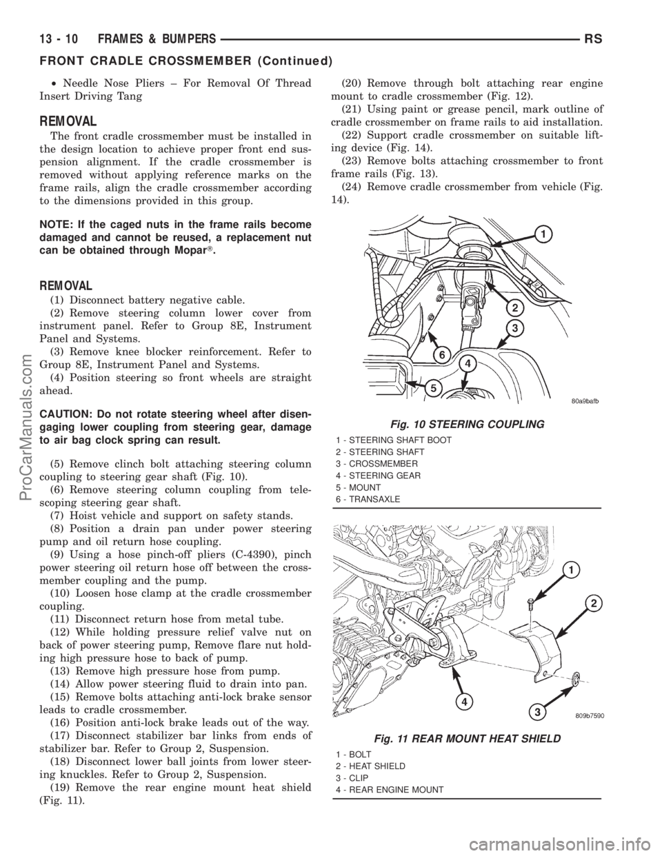
(5) Remove clinch bolt attaching steering column
coupling to steering gear shaft (Fig. 10).
(6) Remove steering column coupling from tele-
scoping steering gear shaft.
(7) Hoist vehicle and support on safety stands.
(8) Position a drain pan under power steering
pump and oil return hose coupling.
(9) Using a hose pinch-off pliers (C-4390), pinch
power steering oil return hose off between the cross-
member coupling and the pump.
(10) Loosen hose clamp at the cradle crossmember
coupling.
(11) Disconnect return hose from metal tube.
(12) While holding pressure relief valve nut on
back of power steering pump, Remove flare nut hold-
ing high pressure hose to back of pump.
(13) Remove high pressure hose from pump.
(14) Allow power steering fluid to drain into pan.
(15) Remove bolts attaching anti-lock brake sensor
leads to cradle crossmember.
(16) Position anti-lock brake leads out of the way.
(17) Disconnect stabilizer bar links from ends of
stabilizer bar. Refer to Group 2, Suspension.
(18) Disconnect lower ball joints from lower steer-
ing knuckles. Refer to Group 2, Suspension.
(19) Remove the rear engine mount heat shield
(Fig. 11).(20) Remove through bolt attaching rear engine
mount to cradle crossmember (Fig. 12).
(21) Using paint or grease pencil, mark outline of
cradle crossmember on frame rails to aid installation.
(22) Support cradle crossmember on suitable lift-
ing device (Fig. 14).
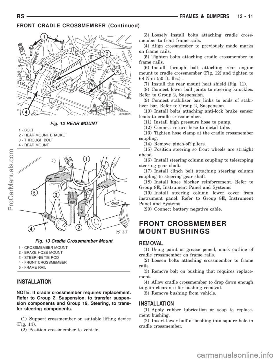
(23) Remove bolts attaching crossmember to front
frame rails (Fig. 13).
(24) Remove cradle crossmember from vehicle (Fig.
14).
Fig. 10 STEERING COUPLING
1 - STEERING SHAFT BOOT
2 - STEERING SHAFT
3 - CROSSMEMBER
4 - STEERING GEAR
5 - MOUNT
6 - TRANSAXLE
Fig. 11 REAR MOUNT HEAT SHIELD
1 - BOLT
2 - HEAT SHIELD
3 - CLIP
4 - REAR ENGINE MOUNT
13 - 10 FRAMES & BUMPERSRS
FRONT CRADLE CROSSMEMBER (Continued)
ProCarManuals.com
Page 1404 of 2321
INSTALLATION
NOTE: If cradle crossmember requires replacement.
Refer to Group 2, Suspension, to transfer suspen-
sion components and Group 19, Steering, to trans-
fer steering components.
(1) Support crossmember on suitable lifting device
(Fig. 14).
(2) Position crossmember to vehicle.(3) Loosely install bolts attaching cradle cross-
member to front frame rails.
(4) Align crossmember to previously made marks
on frame rails.
(5) Tighten bolts attaching cradle crossmember to
frame rails.
(6) Install through bolt attaching rear engine
mount to cradle crossmember (Fig. 12) and tighten to
68 N´m (50 ft. lbs.) .
(7) Install the rear mount heat shield (Fig. 11).
(8) Connect lower ball joints to steering knuckles.
Refer to Group 2, Suspension.
(9) Connect stabilizer bar links to ends of stabi-
lizer bar. Refer to Group 2, Suspension.
(10) Install bolts attaching anti-lock brake sensor
leads to cradle crossmember.
(11) Install high pressure hose to pump.
(12) Connect return hose to metal tube.
(13) Tighten hose clamp at the cradle crossmember
coupling.
(14) Remove pinch-off pliers.
(15) Position steering so front wheels are straight
ahead.
(16) Install steering column coupling to telescoping
steering gear shaft.
(17) Install clinch bolt attaching steering column
coupling to steering gear shaft.
(18) Install knee blocker reinforcement. Refer to
Group 8E, Instrument Panel and Systems.
(19) Install steering column lower cover from
instrument panel. Refer to Group 8E, Instrument
Panel and Systems.
(20) Connect battery negative cable.
FRONT CROSSMEMBER
MOUNT BUSHINGS
REMOVAL
(1) Using paint or grease pencil, mark outline of
cradle crossmember on frame rails.
(2) Loosen bolts attaching crossmember to frame
rails.
(3) Remove bolt on bushing that requires replace-
ment.
(4) Allow cradle crossmember to drop down enough
to gain clearance for bushing removal.
(5) Remove bushing from vehicle.
INSTALLATION
(1) Apply rubber lubrication or soap to replace-
ment bushing.
(2) Insert lower half of bushing into square hole in
cradle crossmember.
Fig. 12 REAR MOUNT
1 - BOLT
2 - REAR MOUNT BRACKET
3 - THROUGH BOLT
4 - REAR MOUNT
Fig. 13 Cradle Crossmember Mount
1 - CROSSMEMBER MOUNT
2 - BRAKE HOSE MOUNT
3 - STEERING TIE ROD
4 - FRONT CROSSMEMBER
5 - FRAME RAIL
RSFRAMES & BUMPERS13-11
FRONT CRADLE CROSSMEMBER (Continued)
ProCarManuals.com