2001 DODGE TOWN AND COUNTRY battery
[x] Cancel search: batteryPage 239 of 2321
Use only brake fluid that was stored in a tightly-
sealed container.
DO NOTuse petroleum-based fluid because seal
damage will result. Petroleum based fluids would be
items such as engine oil, transmission fluid, power
steering fluid etc.
MASTER CYLINDER - RHD
DESCRIPTION
The master cylinder used on right hand drive
(RHD) vehicles functions similarly to that used on
left hand drive (LHD) vehicles. The RHD master cyl-
inder, as well as the RHD power brake booster, is
located in the same area, but lower in the engine
compartment than LHD models (Fig. 1). For that
reason an extension manifold is placed between the
fluid reservoir and master cylinder housing allowing
the fluid reservoir to be positioned in the same loca-
tion as on LHD models.
REMOVAL
CAUTION: Vacuum in the power brake booster must
be pumped down (removed) before removing mas-
ter cylinder from power brake booster. This is nec-
essary to prevent the power brake booster from
sucking in any contamination as the master cylin-der is removed. This can be done simply by pump-
ing the brake pedal, with the vehicle's engine not
running, until a firm feeling brake pedal is achieved.
(1) With engine not running, pump brake pedal
until a firm pedal is achieved (4 or 5 strokes).
(2) Disconnect negative battery terminal.
(3) Disconnect positive battery terminal.
(4) Remove battery shield.
(5) Remove nut and clamp securing battery to tray,
remove battery.
(6) Thoroughly clean all surfaces of the brake fluid
reservoir and master cylinder. Use only solvent such
as MopartBrake Parts Cleaner or equivalent.
(7) Remove wiring harness connector from brake
fluid level switch in master cylinder brake fluid res-
ervoir (Fig. 1).
(8) Disconnect primary and secondary brake tubes
from master cylinder housing (Fig. 2). Install sealing
plugs in the now open brake tube outlet ports.
CAUTION: Before removing the master cylinder
from the power brake vacuum booster, the master
cylinder and vacuum booster must be thoroughly
cleaned. This must be done to prevent dirt particles
from falling into the power brake vacuum booster.
(9) Clean area where master cylinder assembly
attaches to power brake booster. Use only a solvent
such as MopartBrake Parts Cleaner or equivalent.
(10) Remove two nuts attaching master cylinder to
power brake booster (Fig. 2).
(11) Slide master cylinder straight out of power
brake booster.
Fig. 1 RHD MASTER CYLINDER AND POWER
BRAKE BOOSTER
1 - POWER BRAKE BOOSTER
2 - BRAKE FLUID LEVEL SWITCH
3 - FLUID RESERVOIR
4 - MASTER CYLINDER
Fig. 2 RHD MASTER CYLINDER MOUNTING
1 - PRIMARY BRAKE TUBE NUT
2 - SECONDARY BRAKE TUBE NUT
3 - MASTER CYLINDER MOUNTING NUTS
5a - 2 BRAKES - BASERG
FLUID (Continued)
ProCarManuals.com
Page 240 of 2321
CAUTION: A seal on the rear of the master cylinder
is used to create the seal for holding vacuum in the
power brake vacuum booster. The vacuum seal on
the master cylinder MUST be replaced whenever the
master cylinder is removed from the power brake
vacuum booster.
(12) Remove vacuum seal located on the mounting
flange of the master cylinder. The vacuum seal is
removed from master cylinder bycarefullypulling it
off the rear of master cylinder.Do not attempt to
pry the seal off the master cylinder by inserting
a sharp tool between seal and master cylinder
casting.
INSTALLATION
CAUTION: Different types of master cylinders are
used on this vehicle depending on brake options. If
a new master cylinder is being installed, be sure it
is the correct master cylinder for the type of brake
system the vehicle is equipped with.
CAUTION: When replacing the master cylinder on a
vehicle, a NEW vacuum seal MUST be installed on
the master cylinder.
(1) Install a NEW vacuum seal on master cylinder
making sure seal fits squarely in groove of master
cylinder casting.
(2) Position master cylinder on studs of power
brake booster, aligning booster push rod with master
cylinder piston.
(3) Install the two master cylinder mounting nuts
(Fig. 2). Tighten both mounting nuts to a torque of
25 N´m (225 in. lbs.).
CAUTION: When tightening the primary and sec-
ondary brake tube nuts at master cylinder, be sure
brake tubes do not contact any other components
within the vehicle and that there is slack in the flex-
ible sections of the tubes. This is required due to
the movement between the ABS ICU and the master
cylinder while the vehicle is in motion.
(4) Connect primary and secondary brake tubes to
master cylinder primary and secondary ports (Fig. 2).
Brake tubes must be held securely when tightened to
control orientation of flex section. Tighten tube nuts
to a torque of 17 N´m (145 in. lbs.).
(5) Install wiring harness connector to brake fluid
level switch mounted in brake fluid reservoir (Fig. 1).
(6) Install battery, clamp and nut.
(7) Install battery shield.
(8) Connect positive battery terminal.
(9) Connect negative battery terminal.(10) Fill master cylinder with clean, fresh Mopart
Brake Fluid or equivalent.
(11) Road test vehicle to ensure proper operation of
brakes.
PEDAL TORQUE SHAFT
REMOVAL
(1) Remove the instrument panel. (Refer to 23 -
BODY/INSTRUMENT PANEL/INSTRUMENT
PANEL ASSEMBLY - REMOVAL)
(2) Remove the HVAC housing. (Refer to 24 -
HEATING & AIR CONDITIONING/DISTRIBUTION/
HVAC HOUSING - REMOVAL)
(3) Remove the retaining clip at the torque shaft
end of the brake pedal-to-torque shaft link. Remove
the link from the torque shaft. Discard the retaining
clip. It is not to be reused. Replace with a new clip
when reassembled.
(4) Locate the booster input rod-to-brake pedal
torque shaft connection and remove the retaining clip
(Fig. 3). Discard the retaining clip. It is not to be
reused. Replace with a new clip when reassembled.
(5) Remove the four (4) brake booster retaining
nuts from inside the passenger compartment (Fig. 4).
(6) Remove the retaining nut from the brake
booster bracket located above the booster in the
engine compartment (Fig. 4).
(7) Remove the power brake booster bracket.
(8) Rotate the pedal torque shaft and remove it out
the left side of the vehicle.
Fig. 3 POWER BRAKE BOOSTER BRACKET
1 - BOOSTER BRACKET
2 - PEDAL TORQUE SHAFT
3 - RETAINING CLIP
4 - BOOSTER MOUNTING NUTS
RGBRAKES - BASE5a-3
MASTER CYLINDER - RHD (Continued)
ProCarManuals.com
Page 241 of 2321
INSTALLATION
(1) Lubricate both ends of the torque shaft with
MS-4517 Lubricant or equivalent and install the
torque shaft from the left side reversing the removal
procedure.
(2) Install the brake booster bracket on the left
end of the shaft.
(3) Install the four brake booster retaining nuts
inside the passenger compartment. Tighten the
mounting nuts to a torque of 29 N´m (250 in. lbs.).
(4) Install the retaining nut for the brake booster
bracket in the engine compartment. Tighten the
mounting nuts to a torque of 29 N´m (250 in. lbs.).
(5) Using lubriplate, or equivalent, coat the sur-
face of the brake pedal torque shaft pin where it con-
tacts the booster input rod. Also coat the surface of
the brake pedal torque shaft pin where it contacts
the brake pedal link.
CAUTION: When installing the power brake booster
input rod on the brake pedal torque shaft pin, do
not reuse the old retaining clip.(6) Install booster input rod on brake pedal torque
shaft pin and install a NEW retaining clip (Fig. 3).
CAUTION: When installing the brake pedal link on
the brake pedal torque shaft pin, do not reuse the
old retaining clip.
(7) Connect the brake pedal link to the torque
shaft. Install a NEW retaining clip at the torque
shaft end of the brake pedal-to-torque shaft link.
(8) Install the HVAC housing. (Refer to 24 - HEAT-
ING & AIR CONDITIONING/DISTRIBUTION/HVAC
HOUSING - INSTALLATION)
(9) Install the instrument panel. (Refer to 23 -
BODY/INSTRUMENT PANEL/INSTRUMENT
PANEL ASSEMBLY - INSTALLATION)
CAUTION: Do not reuse the original brake lamp
switch. The switch can only be adjusted once. That
is during initial installation of the switch. If the
switch is not adjusted properly or has been
removed for some service, a new switch must be
installed and adjusted.
(10) Remove and replace the brake lamp switch
with a NEW switch. (Refer to 8 - ELECTRICAL/
LAMPS/LIGHTING - EXTERIOR/BRAKE LAMP
SWITCH - REMOVAL), (Refer to 8 - ELECTRICAL/
LAMPS/LIGHTING - EXTERIOR/BRAKE LAMP
SWITCH - INSTALLATION)
(11) Road test vehicle to ensure proper operation of
the brakes.POWER BRAKE BOOSTER -
RHD
REMOVAL
CAUTION: Reserve vacuum in power brake booster
must be pumped down (removed) before removing
master cylinder from booster. This is necessary to
prevent booster from sucking in any contamination
as master cylinder is removed. This can be done
simply by pumping the brake pedal, with the vehi-
cle's engine not running, until a firm feeling brake
pedal is achieved.
(1) With engine not running, pump the brake
pedal until a firm pedal is achieved (4 or 5 strokes).
(2) Remove negative battery cable terminal from
battery.
(3) Remove positive battery cable terminal from
battery.
(4) Remove battery thermal guard shield.
(5) Remove battery clamp, nut and battery from
the battery tray.
Fig. 4 BOOSTER, TORQUE SHAFT AND PEDAL
MOUNTING
1 - PEDAL MOUNTING NUT
2 - BRAKE PEDAL ASSEMBLY
3 - PEDAL MOUNTING NUT
4 - PEDAL TORQUE SHAFT
5 - BOOSTER MOUNTING NUT
6 - BOOSTER BRACKET
7 - POWER BRAKE BOOSTER
8 - BOOSTER BRACKET MOUNTING NUT
5a - 4 BRAKES - BASERG
PEDAL TORQUE SHAFT (Continued)
ProCarManuals.com
Page 242 of 2321
(6) If the vehicle is equipped with speed control,
disconnect the vacuum hose at the vacuum tank built
into the battery tray.
(7) Remove the two nuts and one bolt securing bat-
tery tray in place. Remove battery tray.
(8) If vehicle is equipped with speed control:
(a) Disconnect wiring harness connector from
the speed control servo.
(b) Remove the two servo mounting nuts.
(c) Lay speed control servo off to the side, out of
the way.
(9) If the vehicle is equipped with the 2.5L diesel
engine, remove the coolant recovery pressure con-
tainer and bracket. (Refer to 7 - COOLING/ENGINE/
COOLANT RECOVERY PRESS CONTAINER -
REMOVAL)
(10) Disconnect wiring harness connector from
brake fluid level switch in master cylinder fluid res-
ervoir (Fig. 5).
CAUTION: Before removing the master cylinder
from the power brake vacuum booster, the master
cylinder and vacuum booster must be thoroughly
cleaned. This must be done to prevent dirt particles
from falling into the power brake vacuum booster.
(11) Clean area where master cylinder assembly
attaches to power brake booster. Use only a solvent
such as MopartBrake Parts Cleaner or equivalent.
NOTE: It is not necessary to remove the brake
tubes from the master cylinder when removing the
master cylinder from the booster.(12) Remove two nuts attaching master cylinder to
power brake booster (Fig. 6).
(13) Slide master cylinder straight out of power
brake booster. Lay master cylinder with primary and
secondary tubes to the side, out of the way.
CAUTION: A seal on the rear of the master cylinder
is used to create the seal for holding vacuum in the
power brake vacuum booster. The vacuum seal on
the master cylinder MUST be replaced whenever the
master cylinder is removed from the power brake
vacuum booster.
(14) Disconnect vacuum hose from check valve
located on booster.DO NOT REMOVE CHECK
VALVE FROM POWER BRAKE BOOSTER.
(15) Under the instrument panel, remove booster
input rod trim cover.
(16) Locate the booster input rod to brake pedal
torque shaft connection under the instrument panel.
Position a small screwdriver between the center tang
on the retaining clip (Fig. 7).
(17) Rotate screwdriver enough to allow retaining
clip center tang to pass over end of brake pedal pin.
Then pull retaining clip off brake pedal torque shaft
pin.Discard retaining clip. It is not to be
reused. Replace only with a new retaining clip
when assembling.
(18) Remove booster input rod from pedal torque
shaft pin.
(19) Remove the three easily accessed mounting
nuts attaching power brake booster to dash panel
and loosen fourth (Fig. 8). As fourth nut is loosened,
push the booster forward periodically until the nut
can be completely removed.
Fig. 5 RHD MASTER CYLINDER AND POWER
BRAKE BOOSTER
1 - POWER BRAKE BOOSTER
2 - BRAKE FLUID LEVEL SWITCH
3 - FLUID RESERVOIR
4 - MASTER CYLINDER
Fig. 6 RHD MASTER CYLINDER MOUNTING
1 - PRIMARY BRAKE TUBE NUT
2 - SECONDARY BRAKE TUBE NUT
3 - MASTER CYLINDER MOUNTING NUTS
RGBRAKES - BASE5a-5
POWER BRAKE BOOSTER - RHD (Continued)
ProCarManuals.com
Page 244 of 2321
CAUTION: When removing the vacuum seal from
the master cylinder, do not use a sharp tool.
(7) Using a soft tool such as a trim stick, remove
the vacuum seal from the master cylinder mounting
flange.
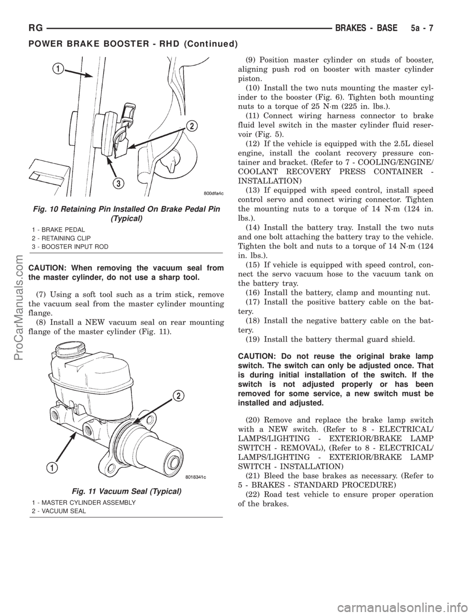
(8) Install a NEW vacuum seal on rear mounting
flange of the master cylinder (Fig. 11).(9) Position master cylinder on studs of booster,
aligning push rod on booster with master cylinder
piston.
(10) Install the two nuts mounting the master cyl-
inder to the booster (Fig. 6). Tighten both mounting
nuts to a torque of 25 N´m (225 in. lbs.).
(11) Connect wiring harness connector to brake
fluid level switch in the master cylinder fluid reser-
voir (Fig. 5).
(12) If the vehicle is equipped with the 2.5L diesel
engine, install the coolant recovery pressure con-
tainer and bracket. (Refer to 7 - COOLING/ENGINE/
COOLANT RECOVERY PRESS CONTAINER -
INSTALLATION)
(13) If equipped with speed control, install speed
control servo and connect wiring connector. Tighten
the mounting nuts to a torque of 14 N´m (124 in.
lbs.).
(14) Install the battery tray. Install the two nuts
and one bolt attaching the battery tray to the vehicle.
Tighten the bolt and nuts to a torque of 14 N´m (124
in. lbs.).
(15) If vehicle is equipped with speed control, con-
nect the servo vacuum hose to the vacuum tank on
the battery tray.
(16) Install the battery, clamp and mounting nut.
(17) Install the positive battery cable on the bat-
tery.
(18) Install the negative battery cable on the bat-
tery.
(19) Install the battery thermal guard shield.
CAUTION: Do not reuse the original brake lamp
switch. The switch can only be adjusted once. That
is during initial installation of the switch. If the
switch is not adjusted properly or has been
removed for some service, a new switch must be
installed and adjusted.
(20) Remove and replace the brake lamp switch
with a NEW switch. (Refer to 8 - ELECTRICAL/
LAMPS/LIGHTING - EXTERIOR/BRAKE LAMP
SWITCH - REMOVAL), (Refer to 8 - ELECTRICAL/
LAMPS/LIGHTING - EXTERIOR/BRAKE LAMP
SWITCH - INSTALLATION)
(21) Bleed the base brakes as necessary. (Refer to
5 - BRAKES - STANDARD PROCEDURE)
(22) Road test vehicle to ensure proper operation
of the brakes.
Fig. 10 Retaining Pin Installed On Brake Pedal Pin
(Typical)
1 - BRAKE PEDAL
2 - RETAINING CLIP
3 - BOOSTER INPUT ROD
Fig. 11 Vacuum Seal (Typical)
1 - MASTER CYLINDER ASSEMBLY
2 - VACUUM SEAL
RGBRAKES - BASE5a-7
POWER BRAKE BOOSTER - RHD (Continued)
ProCarManuals.com
Page 247 of 2321
BRAKES - ABS
TABLE OF CONTENTS
page page
BRAKES - ABS
DESCRIPTION...........................10
ICU (INTEGRATED CONTROL UNIT) - RHD
REMOVAL..............................10DISASSEMBLY...........................11
ASSEMBLY.............................12
INSTALLATION...........................13
BRAKES - ABS
DESCRIPTION - ANTILOCK BRAKE SYSTEM
Four-wheel disc antilock brakes are standard on all
models. The Mark 20e antilock brake system is used
on all models. Depending on whether the vehicle is a
left-hand drive (LHD) or right-hand drive (RHD)
model, the integrated control unit (ICU) is located in
one of two locations. On LHD models, the ICU is
mounted above the front suspension cradle/cross-
member below the master cylinder. On RHD models,
the ICU is located behind the front suspension cra-
dle/crossmember on the left side of the vehicle.
ICU (INTEGRATED CONTROL
UNIT) - RHD
REMOVAL - RHD
NOTE: Before proceeding, review all WARNINGS
AND CAUTIONS.
(1) Disconnect the negative (ground) cable from
the battery and isolate cable.
(2) Using a brake pedal depressor, move and lock
the brake pedal to a position past the first inch of
pedal travel.This will prevent brake fluid from
draining out of the master cylinder when the
brake tubes are removed from the HCU.
(3) Raise vehicle. See Hoisting in the Lubrication
And Maintenance.
(4) Remove the routing clip attaching the ICU wir-
ing harness to the ICU mounting bracket (Fig. 1).CAUTION: Do not apply a 12 volt power source to
any terminals of the HCU connector when discon-
nected.
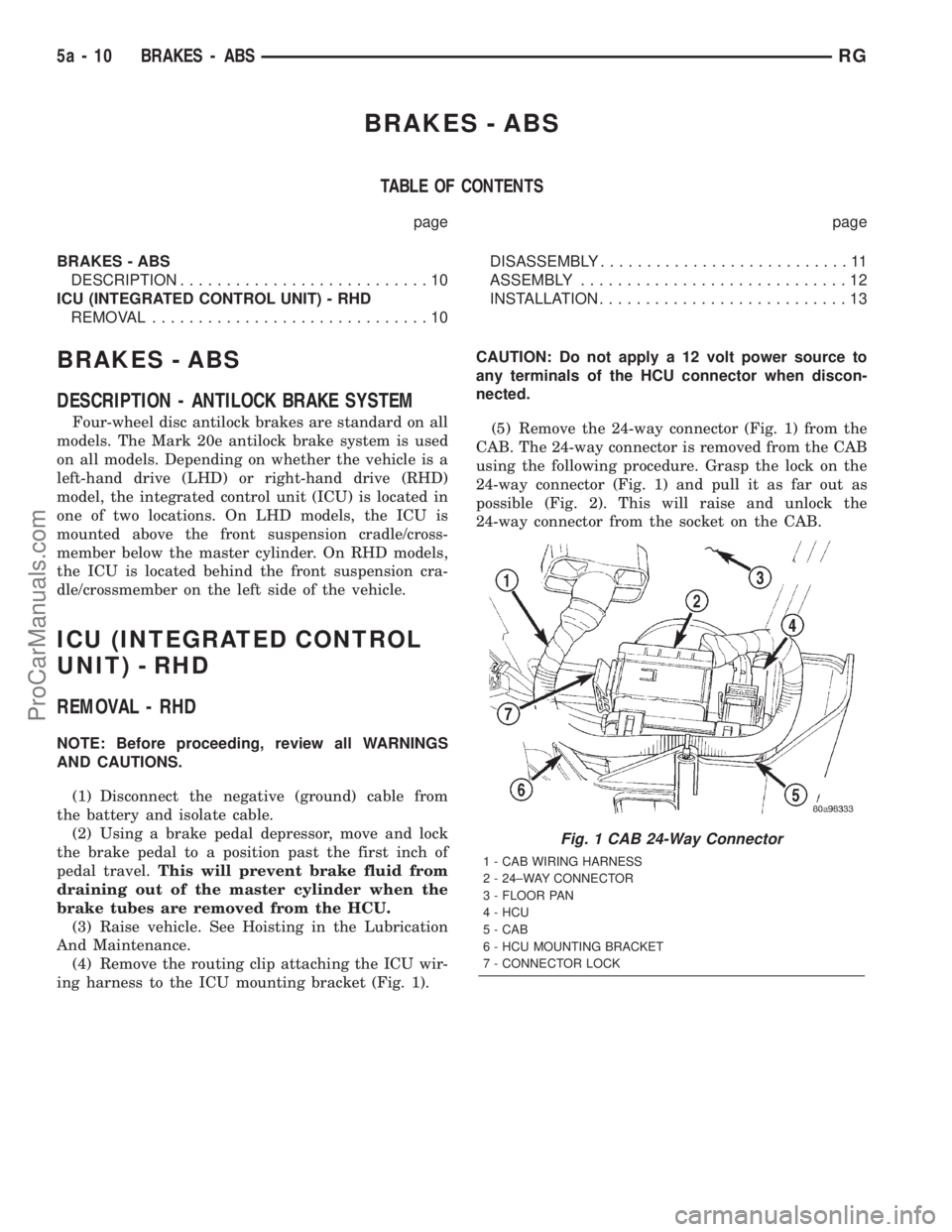
(5) Remove the 24-way connector (Fig. 1) from the
CAB. The 24-way connector is removed from the CAB
using the following procedure. Grasp the lock on the
24-way connector (Fig. 1) and pull it as far out as
possible (Fig. 2). This will raise and unlock the
24-way connector from the socket on the CAB.
Fig. 1 CAB 24-Way Connector
1 - CAB WIRING HARNESS
2 - 24±WAY CONNECTOR
3 - FLOOR PAN
4 - HCU
5 - CAB
6 - HCU MOUNTING BRACKET
7 - CONNECTOR LOCK
5a - 10 BRAKES - ABSRG
ProCarManuals.com
Page 250 of 2321
INSTALLATION - RHD
(1) Install the ICU on the mounting bracket (Fig.
5). Install the 3 bolts (Fig. 5) attaching the ICU to
the mounting bracket. Tighten the 3 mounting bolts
to a torque of 11 N´m (97 in. lbs.).
CAUTION: The ICU mounting bracket to front sus-
pension cradle mounting bolts have a unique corro-
sion protection coating and a special aluminum
washer. For this reason, only the original, or origi-
nal equipment Mopar replacement bolts can be
used to mount the ICU bracket to the front suspen-
sion crossmember.
(2) Install the ICU and its mounting bracket as an
assembly on the front suspension crossmember.
Install the 3 bolts attaching the ICU bracket to the
crossmember (Fig. 4). Tighten the 3 mounting bolts
to a torque of 28 N´m (250 in. lbs.).
CAUTION: Because of the flexible section in the pri-
mary and secondary brake tubes, and the brake
tubes between the HCU and the proportioning
valve, the brake tubes must be held in proper ori-
entation when tightened and torqued. These tubes
must not contact each other or other vehicle com-
ponents when installed. Also, after the brake tubes
are installed on the HCU, ensure all spacer clips are
reinstalled on the brake tubes.
CAUTION: When installing the chassis brake tubes
on the HCU valve block, they must be located cor-
rectly in the valve block to ensure proper ABS oper-
ation. Refer to (Fig. 3) for the correct chassis brake
tube locations.
NOTE: The chassis brake tube attachment locations
to the HCU, are marked on the bottom of the ICU
mounting bracket.
(3) Install the 6 chassis brake tubes into their cor-
rect port locations on the HCU valve block as shown
in (Fig. 3). Tighten the tube nuts to a torque of 17
N´m (145 in. lbs.).
NOTE: Before installing the 24-way connector in the
CAB be sure the seal is properly installed in the
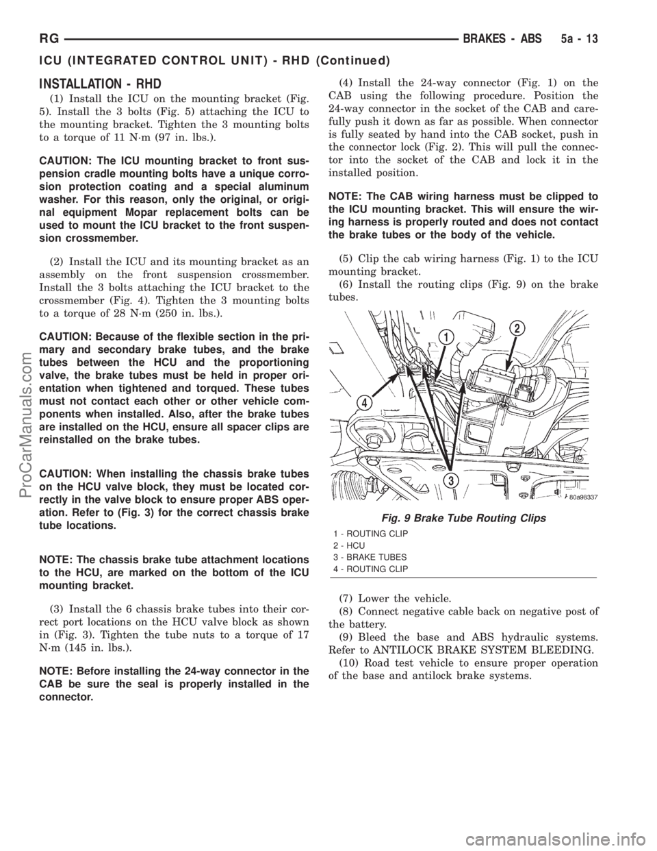
connector.(4) Install the 24-way connector (Fig. 1) on the
CAB using the following procedure. Position the
24-way connector in the socket of the CAB and care-
fully push it down as far as possible. When connector
is fully seated by hand into the CAB socket, push in
the connector lock (Fig. 2). This will pull the connec-
tor into the socket of the CAB and lock it in the
installed position.
NOTE: The CAB wiring harness must be clipped to
the ICU mounting bracket. This will ensure the wir-
ing harness is properly routed and does not contact
the brake tubes or the body of the vehicle.
(5) Clip the cab wiring harness (Fig. 1) to the ICU
mounting bracket.
(6) Install the routing clips (Fig. 9) on the brake
tubes.
(7) Lower the vehicle.
(8) Connect negative cable back on negative post of
the battery.
(9) Bleed the base and ABS hydraulic systems.
Refer to ANTILOCK BRAKE SYSTEM BLEEDING.
(10) Road test vehicle to ensure proper operation
of the base and antilock brake systems.
Fig. 9 Brake Tube Routing Clips
1 - ROUTING CLIP
2 - HCU
3 - BRAKE TUBES
4 - ROUTING CLIP
RGBRAKES - ABS5a-13
ICU (INTEGRATED CONTROL UNIT) - RHD (Continued)
ProCarManuals.com
Page 258 of 2321
DIAGNOSIS AND TESTING - DRIVE PLATE
MISALIGNMENT
Common causes of misalignment are:
²Heat warping
²Mounting drive plate on a dirty crankshaft
flange
²Incorrect bolt tightening
²Improper seating on the crankshaft shoulder
²Loose crankshaft bolts
Clean the crankshaft flange before mounting the
drive plate. Dirt and grease on the flange surface
may misalign the flywheel, causing excessive runout.
Use new bolts when mounting drive plate to crank-
shaft. Tighten drive plate bolts to specified torque
only. Over-tightening can distort the drive plate hub
causing excessive runout.
DIAGNOSIS AND TESTING - CLUTCH COVER
AND DISC RUNOUT
Check condition of the clutch cover before installa-
tion. A warped cover or diaphragm spring will cause
grab and/or incomplete release or engagement. Use
care when handling the clutch assembly. Impact can
distort the cover, diaphragm spring, and release fin-
gers.
DIAGNOSIS AND TESTING - CLUTCH CHATTER
COMPLAINTS
For all clutch chatter complaints, perform the fol-
lowing:
(1) Check for loose, misaligned, or broken engine
and transmission mounts. If present, they should be
corrected at this time. Test vehicle for chatter. If
chatter is gone, there is no need to go any further.
(2) If chatter persists, check hydraulic clutch
release system is functioning properly.
(3) Check for loose connections in drivetrain. Cor-
rect any problems and determine if clutch chatter
complaints have been satisfied. If not:
(a) Remove transaxle.
(b) Check to see if the release bearing is sticky
or binding. Replace bearing, if needed.
(c) Check linkage for excessive wear on the pivot
stud and fork fingers. Replace all worn parts.
(d) Check clutch assembly for contamination
(dirt, oil). Replace clutch assembly, if required.
(e) Check to see if the clutch disc hub splines
are damaged. Replace with new clutch assembly, if
necessary.
(f) Check input shaft splines for damage.
Replace, if necessary.
(g) Check for uneven wear on clutch fingers.
(h) Check for broken clutch cover diaphragm
spring fingers. Replace with new clutch assembly,
if necessary.
SPECIAL TOOLS
SPECIAL TOOLS - T850 TRANSAXLE
CLUTCH RELEASE CABLE -
LHD
REMOVAL
(1) Disconnect battery negative cable.
(2) Raise vehicle on hoist.
(3)Diesel models:Remove underbody splash
shield.
(4) Remove clutch bellhousing cap.
(5) Some models will have a clutch cable retainer
clip at the transaxle to secure it to the case (Fig. 9).
If retainer clip is installed, dislodge clip from from
inside bellhousing using a suitable screwdriver (Fig.
10), pull outward on cable conduit, guiding cable core
wire through slot in bellhousing and disengaging
cable ªTº from clutch release lever (Fig. 11). If
retainer is not installed, disengage clutch cable from
transaxle by pulling outward on cable conduit, guid-
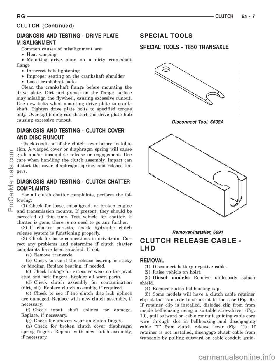
Disconnect Tool, 6638A
Remover/Installer, 6891
RGCLUTCH6a-7
CLUTCH (Continued)
ProCarManuals.com