RIGHT REMOTE RADIO SWITCH - BLACK 2 WAY
CAV CIRCUIT FUNCTION
1 X20 20RD/BK RADIO CONTROL MUX
2 X920 20RD/DB RADIO CONTROL MUX RETURN
RIGHT REPEATER LAMP (BUILT-UP-EXPORT) - GRAY 2 WAY
CAV CIRCUIT FUNCTION
1 A701 18BR/RD FUSED B(+) (HAZARD)
2 L162 20WT/VT RIGHT SIDE REPEATER LAMP FEED
RIGHT SEAT AIRBAG - YELLOW 2 WAY
CAV CIRCUIT FUNCTION
1 R32 18LB/OR (EXCEPT BUILT-UP-EX-
PORT)RIGHT SEAT SQUIB LINE 1
1 R34 18WT/BK (BUILT UP EXPORT) RIGHT SEAT SQUIB LINE 2
2 R32 18DG/WT (BUILT UP EXPORT) RIGHT SEAT SQUIB LINE 1
2 R34 18LB/WT (EXCEPT BUILT-UP-EX-
PORT)RIGHT SEAT SQUIB LINE 2
RIGHT SIDE IMPACT AIRBAG CONTROL MODULE - YELLOW/RED 7 WAY
CAV CIRCUIT FUNCTION
1 R32 18LB/OR RIGHT SEAT SQUIB LINE 1
2 R34 18LB/WT RIGHT SEAT SQUIB LINE 2
3- -
4 D25 20WT/VT PCI BUS
5 F214 18PK/LG FCM OUTPUT (RUN-START)
6- -
7 Z104 18BK/LG GROUND
RIGHT SLIDING DOOR CONTROL MODULE C1 (POWER SLIDING DOOR) - BLACK 8 WAY
CAV CIRCUIT FUNCTION
1 Q44 18OR/GY RIGHT CINCH/RELEASE MOTOR CLUTCH DRIVER
2 Q68 16TN/BR RIGHT SLIDING DOOR OPEN DRIVER
3 Q70 16TN/OR RIGHT SLIDING DOOR CLOSE DRIVER
4- -
5 A113 14WT/RD FUSED B(+)
6- -
7- -
8 Z124 14BK GROUND
RG8W-80 CONNECTOR PIN-OUTS8Wa - 80 - 113
ProCarManuals.com
(7) Install the splash shields below the engine
compartment.
(8) Lower the vehicle.
(9) Connect the negative (-) battery cable on the
negative battery post.
(10) Fill and bleed the power steering system
using the Power Steering Pump Initial Operation
Procedure (Refer to 19 - STEERING/PUMP - STAN-
DARD PROCEDURE).
(11) Inspect for leaks.
RESERVOIR
DESCRIPTION - RESERVOIR (2.5L DIESEL)
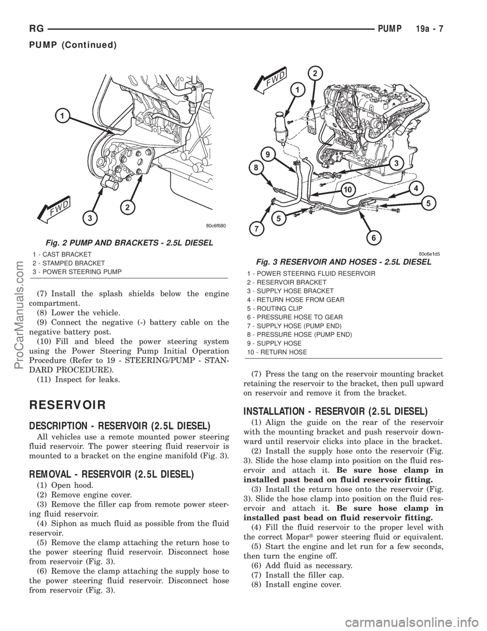
All vehicles use a remote mounted power steering
fluid reservoir. The power steering fluid reservoir is
mounted to a bracket on the engine manifold (Fig. 3).
REMOVAL - RESERVOIR (2.5L DIESEL)
(1) Open hood.
(2) Remove engine cover.
(3) Remove the filler cap from remote power steer-
ing fluid reservoir.
(4) Siphon as much fluid as possible from the fluid
reservoir.
(5) Remove the clamp attaching the return hose to
the power steering fluid reservoir. Disconnect hose
from reservoir (Fig. 3).
(6) Remove the clamp attaching the supply hose to
the power steering fluid reservoir. Disconnect hose
from reservoir (Fig. 3).(7)
Press the tang on the reservoir mounting bracket
retaining the reservoir to the bracket, then pull upward
on reservoir and remove it from the bracket.
INSTALLATION - RESERVOIR (2.5L DIESEL)
(1) Align the guide on the rear of the reservoir
with the mounting bracket and push reservoir down-
ward until reservoir clicks into place in the bracket.
(2) Install the supply hose onto the reservoir (Fig.
3). Slide the hose clamp into position on the fluid res-
ervoir and attach it.Be sure hose clamp in
installed past bead on fluid reservoir fitting.
(3) Install the return hose onto the reservoir (Fig.
3). Slide the hose clamp into position on the fluid res-
ervoir and attach it.Be sure hose clamp in
installed past bead on fluid reservoir fitting.
(4)
Fill the fluid reservoir to the proper level with
the correct Mopartpower steering fluid or equivalent.
(5) Start the engine and let run for a few seconds,
then turn the engine off.
(6) Add fluid as necessary.
(7) Install the filler cap.
(8) Install engine cover.
Fig. 2 PUMP AND BRACKETS - 2.5L DIESEL
1 - CAST BRACKET
2 - STAMPED BRACKET
3 - POWER STEERING PUMP
Fig. 3 RESERVOIR AND HOSES - 2.5L DIESEL
1 - POWER STEERING FLUID RESERVOIR
2 - RESERVOIR BRACKET
3 - SUPPLY HOSE BRACKET
4 - RETURN HOSE FROM GEAR
5 - ROUTING CLIP
6 - PRESSURE HOSE TO GEAR
7 - SUPPLY HOSE (PUMP END)
8 - PRESSURE HOSE (PUMP END)
9 - SUPPLY HOSE
10 - RETURN HOSE
RGPUMP19a-7
PUMP (Continued)
ProCarManuals.com