2001 DODGE TOWN AND COUNTRY fuel filter
[x] Cancel search: fuel filterPage 45 of 2321
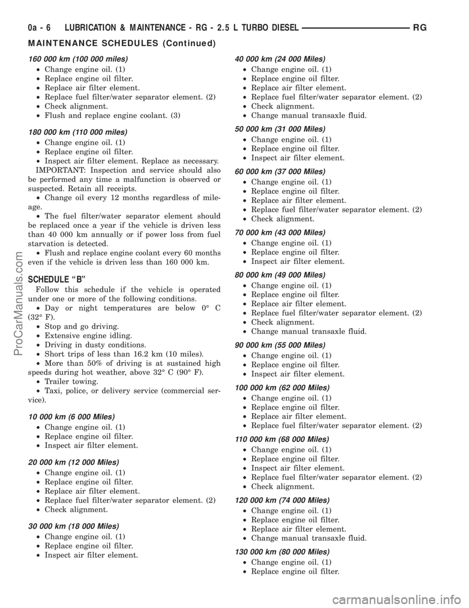
160 000 km (100 000 miles)
²Change engine oil. (1)
²Replace engine oil filter.
²Replace air filter element.
²Replace fuel filter/water separator element. (2)
²Check alignment.
²Flush and replace engine coolant. (3)
180 000 km (110 000 miles)
²Change engine oil. (1)
²Replace engine oil filter.
²Inspect air filter element. Replace as necessary.
IMPORTANT: Inspection and service should also
be performed any time a malfunction is observed or
suspected. Retain all receipts.
²Change oil every 12 months regardless of mile-
age.
²The fuel filter/water separator element should
be replaced once a year if the vehicle is driven less
than 40 000 km annually or if power loss from fuel
starvation is detected.
²
Flush and replace engine coolant every 60 months
even if the vehicle is driven less than 160 000 km.
SCHEDULE ªBº
Follow this schedule if the vehicle is operated
under one or more of the following conditions.
²Day or night temperatures are below 0É C
(32É F).
²Stop and go driving.
²Extensive engine idling.
²Driving in dusty conditions.
²Short trips of less than 16.2 km (10 miles).
²More than 50% of driving is at sustained high
speeds during hot weather, above 32É C (90É F).
²Trailer towing.
²Taxi, police, or delivery service (commercial ser-
vice).
10 000 km (6 000 Miles)
²Change engine oil. (1)
²Replace engine oil filter.
²Inspect air filter element.
20 000 km (12 000 Miles)
²Change engine oil. (1)
²Replace engine oil filter.
²Replace air filter element.
²Replace fuel filter/water separator element. (2)
²Check alignment.
30 000 km (18 000 Miles)
²Change engine oil. (1)
²Replace engine oil filter.
²Inspect air filter element.
40 000 km (24 000 Miles)
²Change engine oil. (1)
²Replace engine oil filter.
²Replace air filter element.
²Replace fuel filter/water separator element. (2)
²Check alignment.
²Change manual transaxle fluid.
50 000 km (31 000 Miles)
²Change engine oil. (1)
²Replace engine oil filter.
²Inspect air filter element.
60 000 km (37 000 Miles)
²Change engine oil. (1)
²Replace engine oil filter.
²Replace air filter element.
²Replace fuel filter/water separator element. (2)
²Check alignment.
70 000 km (43 000 Miles)
²Change engine oil. (1)
²Replace engine oil filter.
²Inspect air filter element.
80 000 km (49 000 Miles)
²Change engine oil. (1)
²Replace engine oil filter.
²Replace air filter element.
²Replace fuel filter/water separator element. (2)
²Check alignment.
²Change manual transaxle fluid.
90 000 km (55 000 Miles)
²Change engine oil. (1)
²Replace engine oil filter.
²Inspect air filter element.
100 000 km (62 000 Miles)
²Change engine oil. (1)
²Replace engine oil filter.
²Replace air filter element.
²Replace fuel filter/water separator element. (2)
110 000 km (68 000 Miles)
²Change engine oil. (1)
²Replace engine oil filter.
²Inspect air filter element.
²Replace fuel filter/water separator element. (2)
²Check alignment.
120 000 km (74 000 Miles)
²Change engine oil. (1)
²Replace engine oil filter.
²Replace air filter element.
²Change manual transaxle fluid.
130 000 km (80 000 Miles)
²Change engine oil. (1)
²Replace engine oil filter.
0a - 6 LUBRICATION & MAINTENANCE - RG - 2.5 L TURBO DIESELRG
MAINTENANCE SCHEDULES (Continued)
ProCarManuals.com
Page 46 of 2321

²Inspect air filter element.
²Replace fuel filter/water separator element. (2)
²Check alignment.
140 000 km (86 000 Miles)
²Change engine oil. (1)
²Replace engine oil filter.
²Replace air filter element.
150 000 km (93 000 Miles)
²Change engine oil. (1)
²Replace engine oil filter.
²Inspect air filter element.
²Replace fuel filter/water separator element. (2)
²Check alignment.
160 000 km (100 000 Miles)
²Change engine oil. (1)
²Replace engine oil filter.
²Replace air filter element.
²Flush and replace engine coolant. (3)
²Change oil every 12 months regardless of mile-
age.
²The fuel filter/water separator element should
be replaced once a year if the vehicle is driven less
than 20 000 km annually or if power loss from fuel
starvation is detected.
²
Flush and replace engine coolant every 60 months
even if the vehicle is driven less than 160 000 km.
²Change manual transaxle fluid.
HOISTING
STANDARD PROCEDURE - HOISTING
Refer to Owner's Manual provided with vehicle for
proper emergency jacking procedures.
WARNING: THE HOISTING AND JACK LIFTING
POINTS PROVIDED ARE FOR A COMPLETE VEHI-
CLE. WHEN THE ENGINE OR REAR SUSPENSION
IS REMOVED FROM A VEHICLE, THE CENTER OF
GRAVITY IS ALTERED MAKING SOME HOISTING
CONDITIONS UNSTABLE. PROPERLY SUPPORT OR
SECURE VEHICLE TO HOISTING DEVICE WHEN
THESE CONDITIONS EXIST.
CAUTION: Do not position hoisting device on any
suspension component, including the front suspen-
sion crossmember, the rear leaf springs, and the
rear axle. Do not hoist on the front and rear
bumpers, the lower liftgate crossmember, the lower
radiator crossmember, the down standing flanges
on the sill or the front engine mount.
FOR PROPER HOIST PLACEMENT REFER
TO (Fig. 7).The hoisting points are identified by S.A.E.
inverted triangle hoisting symbols (Fig. 7). The front
hoisting points are at the bottom of the font rail
below the hoisting symbol approximately 250mm
behind the front suspension crossmember. When
using outboard lift hoists, verify that the hoist lift
pads have been properly adjusted to eliminate con-
tact between the hoist arm and the down standing
flange on the sill. The rear hoisting points are the
leaf spring front mounting brackets. The hoist pad
must be positioned to pick up the flanges on the
bracket, not the leaf spring.
When servicing the leaf springs or the leaf spring
mounting brackets, special provisions are required to
support the rear of the vehicle. Position the rear
hoist pads under the horizontal surface on the bot-
tom of the sill, inboard adjacent to the flange and
centered fore/aft between the jacking indicator tabs
on the lower flange.DO NOT HOIST ON THE
FLANGE.Place a soft pad between the hoist and the
painted surface on the sill to avoid scratching the fin-
ish.
Fig. 7 HOISTING AND JACKING POINTS
1 - Drive On Lift
2 - Frame Contact Lift (Single Post)
Chassis Lift (Non-Axle Dual Post)
Outboard Lift (Dual Post)
Floor Jack
3 - S.A.E. Hoisting Symbols
RGLUBRICATION & MAINTENANCE - RG - 2.5 L TURBO DIESEL0a-7
MAINTENANCE SCHEDULES (Continued)
ProCarManuals.com
Page 472 of 2321

INSTRUMENT CLUSTER
TABLE OF CONTENTS
page page
INSTRUMENT CLUSTER
DESCRIPTION............................1OPERATION.............................1
INSTRUMENT CLUSTER
DESCRIPTION
WATER IN FUEL LAMP
The Water In Fuel Lamp is located in the instru-
ment cluster. When moisture is found within the fuel
system, the sensor sends a message via the PCI data
bus to the instrument cluster. The sensor is located
underneath the vehicle, directly above the rear axle.
The sensor is housed within the fuel filter/water sep-
arator assembly cover. The sensor is not serviced sep-
arately. If found defective, the entire assembly cover
must be replaced.
OPERATION
WATER IN FUEL LAMP
The Water In Fuel Sensor is a resistive type
switch. It is calibrated to sense the different resis-
tance between diesel fuel and water. When water
enters the fuel system, it is caught in the bottom of
the fuel filter/water separator assembly, where the
sensor is located. Water has less resistance than die-
sel fuel. The sensor then sends a PCI data bus mes-
sage to the instrument cluster to illuminate the
lamp.
If the lamp is inoperative, perform the self diag-
nostic test on the instrument cluster to check the
lamp operation before continuing diagnosis.
RGINSTRUMENT CLUSTER8Ja-1
ProCarManuals.com
Page 1162 of 2321
(7) After the oil leak root cause and appropriate
corrective action have been identified, replace compo-
nent(s) as necessary.
DIAGNOSIS AND TESTING - ENGINE
Engine diagnosis is helpful in determining the
causes of malfunctions not detected and remedied by
routine maintenance.
These malfunctions may be classified as either
mechanical (e.g., a strange noise), or performance
(e.g., engine idles rough and stalls).
Refer to the Engine Mechanical and the Engine
Performance diagnostic charts, for possible causes
and corrections of malfunctions (Refer to 9 - ENGINE
- DIAGNOSIS AND TESTING - MECHANICAL)
(Refer to 9 - ENGINE - DIAGNOSIS AND TESTING
- PERFORMANCE).For fuel system diagnosis, (Refer to 14 - FUEL
SYSTEM/FUEL DELIVERY - DIAGNOSIS AND
TESTING).
Additional tests and diagnostic procedures may be
necessary for specific engine malfunctions that can-
not be isolated with the Service Diagnosis charts.
Information concerning additional tests and diagno-
sis is provided within the following:
²Cylinder Compression Pressure Test
²Cylinder Combustion Pressure Leakage Test
²Engine Cylinder Head Gasket Failure Diagnosis
²Intake Manifold Leakage Diagnosis
²Lash Adjuster (Tappet) Noise Diagnosis
²Engine Oil Leak Inspection
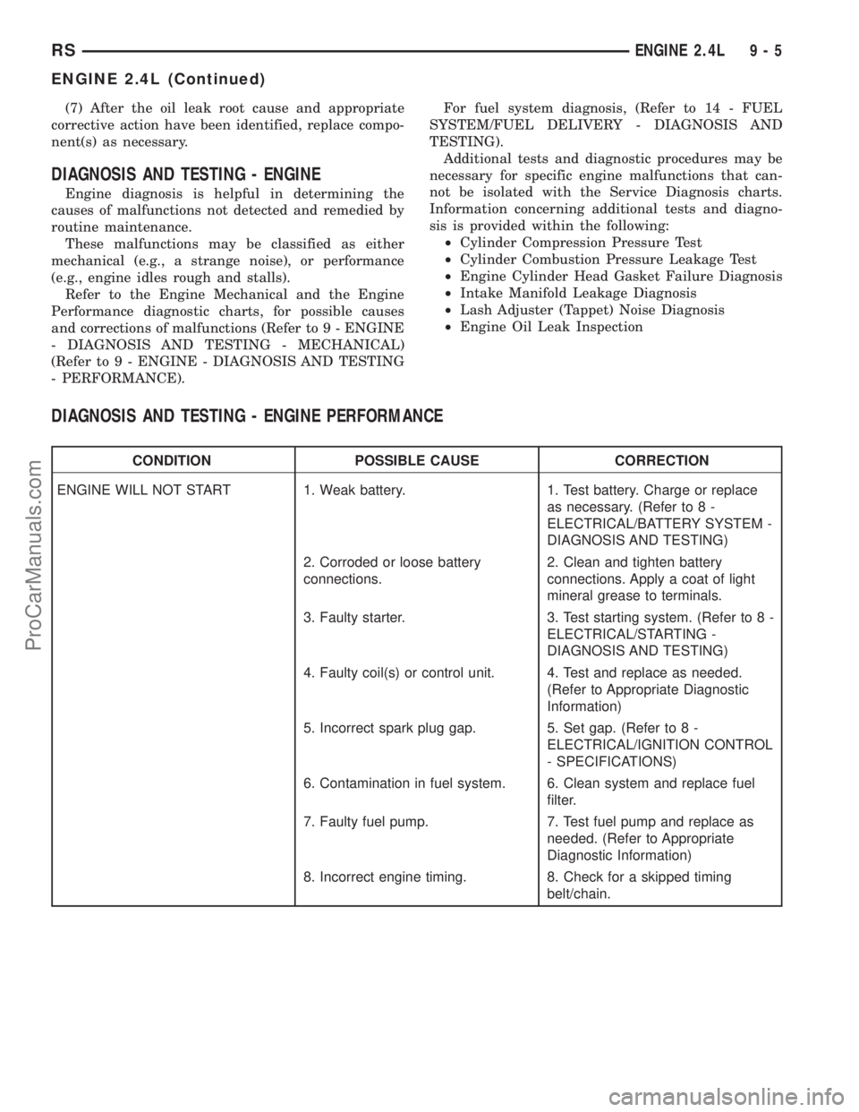
DIAGNOSIS AND TESTING - ENGINE PERFORMANCE
CONDITION POSSIBLE CAUSE CORRECTION
ENGINE WILL NOT START 1. Weak battery. 1. Test battery. Charge or replace
as necessary. (Refer to 8 -
ELECTRICAL/BATTERY SYSTEM -
DIAGNOSIS AND TESTING)
2. Corroded or loose battery
connections.2. Clean and tighten battery
connections. Apply a coat of light
mineral grease to terminals.
3. Faulty starter. 3. Test starting system. (Refer to 8 -
ELECTRICAL/STARTING -
DIAGNOSIS AND TESTING)
4. Faulty coil(s) or control unit. 4. Test and replace as needed.
(Refer to Appropriate Diagnostic
Information)
5. Incorrect spark plug gap. 5. Set gap. (Refer to 8 -
ELECTRICAL/IGNITION CONTROL
- SPECIFICATIONS)
6. Contamination in fuel system. 6. Clean system and replace fuel
filter.
7. Faulty fuel pump. 7. Test fuel pump and replace as
needed. (Refer to Appropriate
Diagnostic Information)
8. Incorrect engine timing. 8. Check for a skipped timing
belt/chain.
RSENGINE 2.4L9-5
ENGINE 2.4L (Continued)
ProCarManuals.com
Page 1163 of 2321
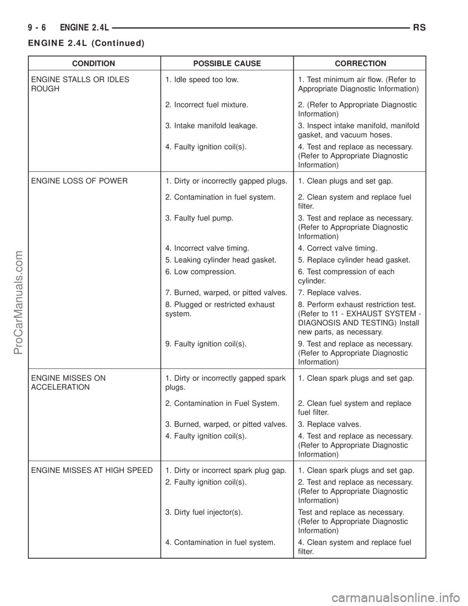
CONDITION POSSIBLE CAUSE CORRECTION
ENGINE STALLS OR IDLES
ROUGH1. Idle speed too low. 1. Test minimum air flow. (Refer to
Appropriate Diagnostic Information)
2. Incorrect fuel mixture. 2. (Refer to Appropriate Diagnostic
Information)
3. Intake manifold leakage. 3. Inspect intake manifold, manifold
gasket, and vacuum hoses.
4. Faulty ignition coil(s). 4. Test and replace as necessary.
(Refer to Appropriate Diagnostic
Information)
ENGINE LOSS OF POWER 1. Dirty or incorrectly gapped plugs. 1. Clean plugs and set gap.
2. Contamination in fuel system. 2. Clean system and replace fuel
filter.
3. Faulty fuel pump. 3. Test and replace as necessary.
(Refer to Appropriate Diagnostic
Information)
4. Incorrect valve timing. 4. Correct valve timing.
5. Leaking cylinder head gasket. 5. Replace cylinder head gasket.
6. Low compression. 6. Test compression of each
cylinder.
7. Burned, warped, or pitted valves. 7. Replace valves.
8. Plugged or restricted exhaust
system.8. Perform exhaust restriction test.
(Refer to 11 - EXHAUST SYSTEM -
DIAGNOSIS AND TESTING) Install
new parts, as necessary.
9. Faulty ignition coil(s). 9. Test and replace as necessary.
(Refer to Appropriate Diagnostic
Information)
ENGINE MISSES ON
ACCELERATION1. Dirty or incorrectly gapped spark
plugs.1. Clean spark plugs and set gap.
2. Contamination in Fuel System. 2. Clean fuel system and replace
fuel filter.
3. Burned, warped, or pitted valves. 3. Replace valves.
4. Faulty ignition coil(s). 4. Test and replace as necessary.
(Refer to Appropriate Diagnostic
Information)
ENGINE MISSES AT HIGH SPEED 1. Dirty or incorrect spark plug gap. 1. Clean spark plugs and set gap.
2. Faulty ignition coil(s). 2. Test and replace as necessary.
(Refer to Appropriate Diagnostic
Information)
3. Dirty fuel injector(s). Test and replace as necessary.
(Refer to Appropriate Diagnostic
Information)
4. Contamination in fuel system. 4. Clean system and replace fuel
filter.
9 - 6 ENGINE 2.4LRS
ENGINE 2.4L (Continued)
ProCarManuals.com
Page 1167 of 2321
(1) Inspect air cleaner, induction system and
intake manifold to insure system is dry and clear of
foreign material.
(2) Remove negative battery cable.
(3) Place a shop towel around the spark plugs
when removing them from the engine. This will catch
any fluid that may possibly be in the cylinder under
pressure.
(4) With all spark plugs removed, rotate engine
crankshaft using a breaker bar and socket.
(5) Identify the fluid in the cylinder(s) (i.e., cool-
ant, fuel, oil or other).
(6) Make sure all fluid has been removed from the
cylinders. Inspect engine for damage (i.e., connecting
rods, pistons, valves, etc.)
(7) Repair engine or components as necessary to
prevent this problem from re-occurring.
CAUTION: Squirt approximately one teaspoon of oil
into the cylinders, rotate engine to lubricate the cyl-
inder walls to prevent damage on restart.
(8) Install new spark plugs.
(9) Drain engine oil and remove oil filter.
(10) Install a new oil filter.
(11) Fill engine with specified amount of approved
oil.
(12) Connect negative battery cable.
(13) Start engine and check for any leaks.
STANDARD PROCEDURE - FORM-IN-PLACE
GASKETS AND SEALERS
There are numerous places where form-in-place
gaskets are used on the engine. Care must be taken
when applying form-in-place gaskets to assure
obtaining the desired results.Do not use form-in-
place gasket material unless specified.Bead size,
continuity, and location are of great importance. Too
thin a bead can result in leakage while too much can
result in spill-over which can break off and obstruct
fluid feed lines. A continuous bead of the proper
width is essential to obtain a leak-free gasket.
There are numerous types of form-in-place gasket
materials that are used in the engine area. Mopart
Engine RTV GEN II, MopartATF-RTV, and Mopart
Gasket Maker gasket materials, each have different
properties and can not be used in place of the other.
MOPARtENGINE RTV GEN IIis used to seal
components exposed to engine oil. This material is a
specially designed black silicone rubber RTV that
retains adhesion and sealing properties when
exposed to engine oil. Moisture in the air causes the
material to cure. This material is available in three
ounce tubes and has a shelf life of one year. After one
year this material will not properly cure. Alwaysinspect the package for the expiration date before
use.
MOPARtATF RTVis a specifically designed
black silicone rubber RTV that retains adhesion and
sealing properties to seal components exposed to
automatic transmission fluid, engine coolants, and
moisture. This material is available in three ounce
tubes and has a shelf life of one year. After one year
this material will not properly cure. Always inspect
the package for the expiration date before use.
MOPARtGASKET MAKERis an anaerobic type
gasket material. The material cures in the absence of
air when squeezed between two metallic surfaces. It
will not cure if left in the uncovered tube. The
anaerobic material is for use between two machined
surfaces. Do not use on flexible metal flanges.
MOPARtBED PLATE SEALANTis a unique
(green-in-color) anaerobic type gasket material that
is specially made to seal the area between the bed-
plate and cylinder block without disturbing the bear-
ing clearance or alignment of these components. The
material cures slowly in the absence of air when
torqued between two metallic surfaces, and will rap-
idly cure when heat is applied.
MOPARtGASKET SEALANTis a slow drying,
permanently soft sealer. This material is recom-
mended for sealing threaded fittings and gaskets
against leakage of oil and coolant. Can be used on
threaded and machined parts under all tempera-
tures. This material is used on engines with multi-
layer steel (MLS) cylinder head gaskets. This
material also will prevent corrosion. MopartGasket
Sealant is available in a 13 oz. aerosol can or 4oz./16
oz. can w/applicator.
SEALER APPLICATION
MopartGasket Maker material should be applied
sparingly 1 mm (0.040 in.) diameter or less of sealant
to one gasket surface. Be certain the material sur-
rounds each mounting hole. Excess material can eas-
ily be wiped off. Components should be torqued in
place within 15 minutes. The use of a locating dowel
is recommended during assembly to prevent smear-
ing material off the location.
MopartEngine RTV GEN II or ATF RTV gasket
material should be applied in a continuous bead
approximately 3 mm (0.120 in.) in diameter. All
mounting holes must be circled. For corner sealing, a
3.17 or 6.35 mm (1/8 or 1/4 in.) drop is placed in the
center of the gasket contact area. Uncured sealant
may be removed with a shop towel. Components
should be torqued in place while the sealant is still
wet to the touch (within 10 minutes). The usage of a
locating dowel is recommended during assembly to
prevent smearing material off the location.
9 - 10 ENGINE 2.4LRS
ENGINE 2.4L (Continued)
ProCarManuals.com
Page 1169 of 2321
NOTE: Plastigage is available in a variety of clear-
ance ranges. Use the most appropriate range for
the specifications you are checking.
(4) Install the proper crankshaft bearings to
achieve the specified bearing clearances. (Refer to 9 -
ENGINE/ENGINE BLOCK/CRANKSHAFT MAIN
BEARINGS - STANDARD PROCEDURE) (Refer to 9
- ENGINE/ENGINE BLOCK/CONNECTING ROD
BEARINGS - STANDARD PROCEDURE)
REMOVAL - ENGINE ASSEMBLY
(1) Perform fuel pressure release procedure (Refer
to 14 - FUEL SYSTEM/FUEL DELIVERY - STAN-
DARD PROCEDURE)
(2) Disconnect battery negative cable.
(3) Remove air cleaner housing and inlet tube.
(4) Disconnect the fuel line from fuel rail. (Refer to
14 - FUEL SYSTEM/FUEL DELIVERY/FUEL LINES
- STANDARD PROCEDURE)
(5) Disconnect all vacuum hoses.
(6) Drain cooling system. (Refer to 7 - COOLING -
STANDARD PROCEDURE)
(7) Remove radiator fans. (Refer to 7 - COOLING/
ENGINE/RADIATOR FAN - REMOVAL)
(8) Remove radiator upper and lower hoses.
(9) Disconnect automatic transmission cooler lines
and plug.(10) Disconnect transmission shift linkage and
electrical connectors.
(11) Disconnect throttle body linkage.
(12) Disconnect engine wiring harness.
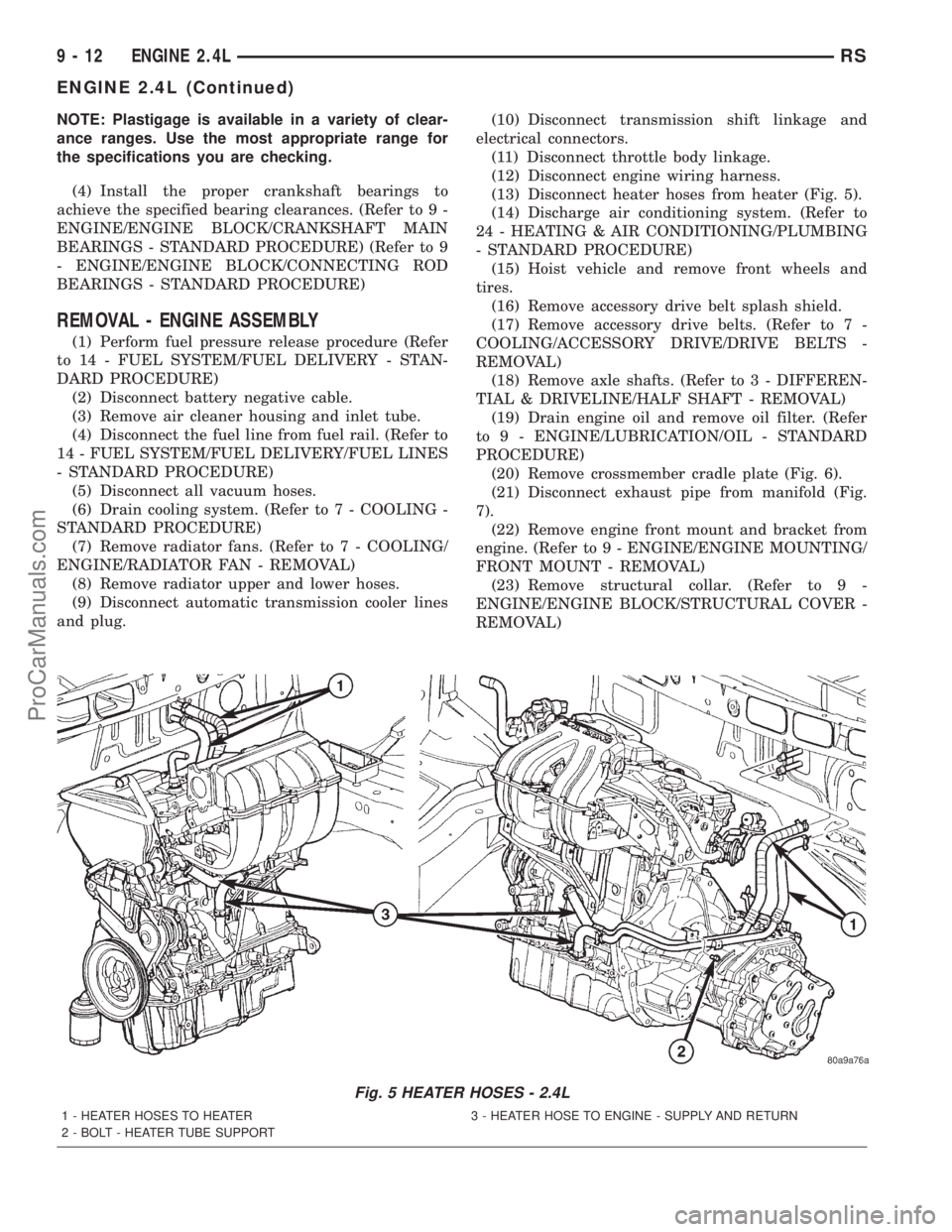
(13) Disconnect heater hoses from heater (Fig. 5).
(14) Discharge air conditioning system. (Refer to
24 - HEATING & AIR CONDITIONING/PLUMBING
- STANDARD PROCEDURE)
(15) Hoist vehicle and remove front wheels and
tires.
(16) Remove accessory drive belt splash shield.
(17) Remove accessory drive belts. (Refer to 7 -
COOLING/ACCESSORY DRIVE/DRIVE BELTS -
REMOVAL)
(18) Remove axle shafts. (Refer to 3 - DIFFEREN-
TIAL & DRIVELINE/HALF SHAFT - REMOVAL)
(19) Drain engine oil and remove oil filter. (Refer
to 9 - ENGINE/LUBRICATION/OIL - STANDARD
PROCEDURE)
(20) Remove crossmember cradle plate (Fig. 6).
(21) Disconnect exhaust pipe from manifold (Fig.
7).
(22) Remove engine front mount and bracket from
engine. (Refer to 9 - ENGINE/ENGINE MOUNTING/
FRONT MOUNT - REMOVAL)
(23) Remove structural collar. (Refer to 9 -
ENGINE/ENGINE BLOCK/STRUCTURAL COVER -
REMOVAL)
Fig. 5 HEATER HOSES - 2.4L
1 - HEATER HOSES TO HEATER 3 - HEATER HOSE TO ENGINE - SUPPLY AND RETURN
2 - BOLT - HEATER TUBE SUPPORT
9 - 12 ENGINE 2.4LRS
ENGINE 2.4L (Continued)
ProCarManuals.com
Page 1180 of 2321
OPERATION
The cylinder head closes the combustion chamber,
allowing the pistons to compress the fuel/air mixture
for ignition. The valves are actuated by the lobe pro-
files on the camshaft to open and close at specified
duration to either allow clean air in the combustion
chamber or the exhaust gases out; depending on the
stroke of the engine.
DIAGNOSIS AND TESTINGÐCYLINDER HEAD
GASKET
A cylinder head gasket leak can be located between
adjacent cylinders or between a cylinder and the
adjacent water jacket.
Possible indications of the cylinder head gasket
leaking between adjacent cylinders are:
²Loss of engine power
²Engine misfiring
²Poor fuel economy
Possible indications of the cylinder head gasket
leaking between a cylinder and an adjacent water
jacket are:
²Engine overheating
²Loss of coolant
²Excessive steam (white smoke) emitting from
exhaust
²Coolant foaming
CYLINDER-TO-CYLINDER LEAKAGE TEST
To determine if an engine cylinder head gasket is
leaking between adjacent cylinders, follow the proce-
dures in Cylinder Compression Pressure Test (Refer
to 9 - ENGINE - DIAGNOSIS AND TESTING). An
engine cylinder head gasket leaking between adja-
cent cylinders will result in approximately a 50±70%
reduction in compression pressure.
CYLINDER-TO-WATER JACKET LEAKAGE TEST
WARNING: USE EXTREME CAUTION WHEN THE
ENGINE IS OPERATING WITH COOLANT PRES-
SURE CAP REMOVED.
VISUAL TEST METHOD
With the engine cool, remove the coolant pressure
cap. Start the engine and allow it to warm up until
thermostat opens.
If a large combustion/compression pressure leak
exists, bubbles will be visible in the coolant.
COOLING SYSTEM TESTER METHOD
WARNING: WITH COOLING SYSTEM TESTER IN
PLACE, PRESSURE WILL BUILD UP FAST. EXCES-
SIVE PRESSURE BUILT UP, BY CONTINUOUS
ENGINE OPERATION, MUST BE RELEASED TO A
SAFE PRESSURE POINT. NEVER PERMIT PRES-
SURE TO EXCEED 138 kPa (20 psi).
Install Cooling System Tester 7700 or equivalent to
pressure cap neck. Start the engine and observe the
tester's pressure gauge. If gauge pulsates with every
power stroke of a cylinder a combustion pressure
leak is evident.
CHEMICAL TEST METHOD
Combustion leaks into the cooling system can also
be checked by using Bloc-Chek Kit C-3685-A or
equivalent. Perform test following the procedures
supplied with the tool kit.
REMOVAL - CYLINDER HEAD
(1) Perform fuel system pressure release procedure
before attempting any repairs.(Refer to 14 -
FUEL SYSTEM/FUEL DELIVERY - SPECIFICA-
TIONS)
(2) Disconnect battery negative cable.
(3) Drain cooling system. (Refer to 7 - COOLING -
STANDARD PROCEDURE)
(4) Remove air filter housing and inlet tube.
(5) Remove upper intake manifold. (Refer to 9 -
ENGINE/MANIFOLDS/INTAKE MANIFOLD -
REMOVAL)
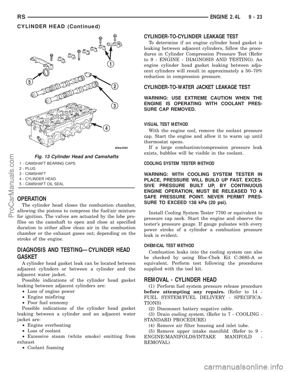
Fig. 13 Cylinder Head and Camshafts
1 - CAMSHAFT BEARING CAPS
2 - PLUG
3 - CAMSHAFT
4 - CYLINDER HEAD
5 - CAMSHAFT OIL SEAL
RSENGINE 2.4L9-23
CYLINDER HEAD (Continued)
ProCarManuals.com