2001 DODGE TOWN AND COUNTRY fuse
[x] Cancel search: fusePage 1089 of 2321
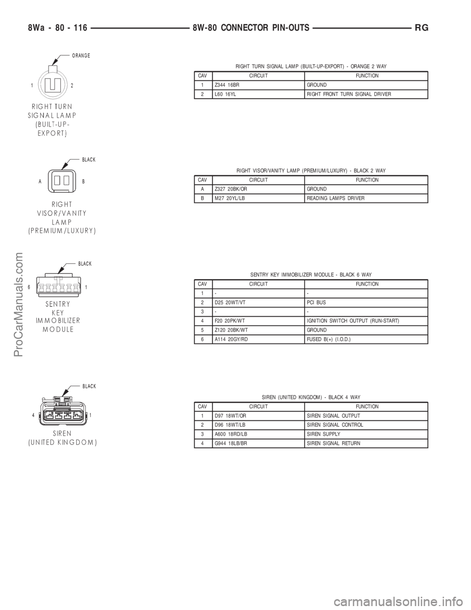
RIGHT TURN SIGNAL LAMP (BUILT-UP-EXPORT) - ORANGE 2 WAY
CAV CIRCUIT FUNCTION
1 Z344 16BR GROUND
2 L60 16YL RIGHT FRONT TURN SIGNAL DRIVER
RIGHT VISOR/VANITY LAMP (PREMIUM/LUXURY) - BLACK 2 WAY
CAV CIRCUIT FUNCTION
A Z327 20BK/OR GROUND
B M27 20YL/LB READING LAMPS DRIVER
SENTRY KEY IMMOBILIZER MODULE - BLACK 6 WAY
CAV CIRCUIT FUNCTION
1- -
2 D25 20WT/VT PCI BUS
3- -
4 F20 20PK/WT IGNITION SWITCH OUTPUT (RUN-START)
5 Z120 20BK/WT GROUND
6 A114 20GY/RD FUSED B(+) (I.O.D.)
SIREN (UNITED KINGDOM) - BLACK 4 WAY
CAV CIRCUIT FUNCTION
1 D97 18WT/OR SIREN SIGNAL OUTPUT
2 D96 18WT/LB SIREN SIGNAL CONTROL
3 A600 18RD/LB SIREN SUPPLY
4 G944 18LB/BR SIREN SIGNAL RETURN
8Wa - 80 - 116 8W-80 CONNECTOR PIN-OUTSRG
ProCarManuals.com
Page 1091 of 2321
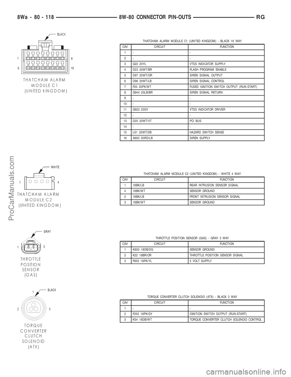
THATCHAM ALARM MODULE C1 (UNITED KINGDOM) - BLACK 16 WAY
CAV CIRCUIT FUNCTION
1- -
2- -
3 G22 20YL VTSS INDICATOR SUPPLY
4 D23 20WT/BR FLASH PROGRAM ENABLE
5 D97 20WT/OR SIREN SIGNAL OUTPUT
6 D96 20WT/LB SIREN SIGNAL CONTROL
7 F20 20PK/WT FUSED IGNITION SWITCH OUTPUT (RUN-START)
8 G944 20LB/BR SIREN SIGNAL RETURN
9- -
10 - -
11 G922 20GY VTSS INDICATOR DRIVER
12 - -
13 D25 20WT/VT PCI BUS
14 - -
15 L91 20WT/DB HAZARD SWITCH SENSE
16 A600 20RD/LB SIREN SUPPLY
THATCHAM ALARM MODULE C2 (UNITED KINGDOM) - WHITE 4 WAY
CAV CIRCUIT FUNCTION
1 18BK/LB REAR INTRUSION SENSOR SIGNAL
4 18BK/WT SENSOR GROUND
2 18BK/LB FRONT INTRUSION SENSOR SIGNAL
3 18BK/WT SENSOR GROUND
THROTTLE POSITION SENSOR (GAS) - GRAY 3 WAY
CAV CIRCUIT FUNCTION
1 K900 18DB/DG SENSOR GROUND
2 K22 18BR/OR THROTTLE POSITION SENSOR SIGNAL
3 F855 18PK/YL 5 VOLT SUPPLY
TORQUE CONVERTER CLUTCH SOLENOID (ATX) - BLACK 3 WAY
CAV CIRCUIT FUNCTION
1- -
2 F202 18PK/GY IGNITION SWITCH OUTPUT (RUN-START)
3 K54 18DB/WT TORQUE CONVERTER CLUTCH SOLENOID CONTROL
8Wa - 80 - 118 8W-80 CONNECTOR PIN-OUTSRG
ProCarManuals.com
Page 1092 of 2321
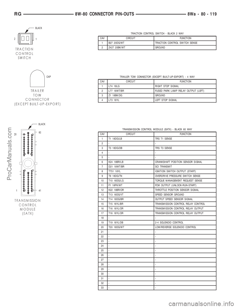
TRACTION CONTROL SWITCH - BLACK 2 WAY
CAV CIRCUIT FUNCTION
1 B27 20DG/WT TRACTION CONTROL SWITCH SENSE
2 Z427 20BK/WT GROUND
TRAILER TOW CONNECTOR (EXCEPT BUILT-UP-EXPORT)-4WAY
CAV CIRCUIT FUNCTION
1 L74 18LG RIGHT STOP SIGNAL
2 L77 18WT/BR FUSED PARK LAMP RELAY OUTPUT (LEFT)
3 Z1 18BK/DG GROUND
4 L73 18YL LEFT STOP SIGNAL
TRANSMISSION CONTROL MODULE (EATX) - BLACK 60 WAY
CAV CIRCUIT FUNCTION
1 T1 18DG/LB TRS T1 SENSE
2- -
3 T3 18DG/DB TRS T3 SENSE
4- -
5- -
6 K24 18BR/LB CRANKSHAFT POSITION SENSOR SIGNAL
7 D21 18WT/BR SCI TRANSMIT
8 T751 18YL IGNITION SWITCH OUTPUT (START)
9 T9 18DG/TN OVERDRIVE PRESSURE SWITCH SENSE
10 T10 18DG/LG TORQUE MANAGEMENT REQUEST SENSE
11 F1 18PK/WT FCM OUTPUT (UNLOCK-RUN-START)
12 K22 18BR/OR THROTTLE POSITION SENSOR SIGNAL
13 T13 18DG/VT SPEED SENSOR GROUND
14 T14 18DG/BR OUTPUT SPEED SENSOR SIGNAL
15 T15 18YL/BR TRANSMISSION CONTROL RELAY CONTROL
16 T16 18YL/OR TRANSMISSION CONTROL RELAY OUTPUT
17 T16 18YL/OR TRANSMISSION CONTROL RELAY OUTPUT
18 - -
19 T19 18YL/DB 2-4 SOLENOID CONTROL
20 T20 18DG/WT LOW/REVERSE SOLENOID CONTROL
21 - -
22 - -
23 - -
24 - -
25 - -
26 - -
27 - -
28 - -
29 - -
30 - -
31 - -
32 - -
33 - -
RG8W-80 CONNECTOR PIN-OUTS8Wa - 80 - 119
ProCarManuals.com
Page 1093 of 2321
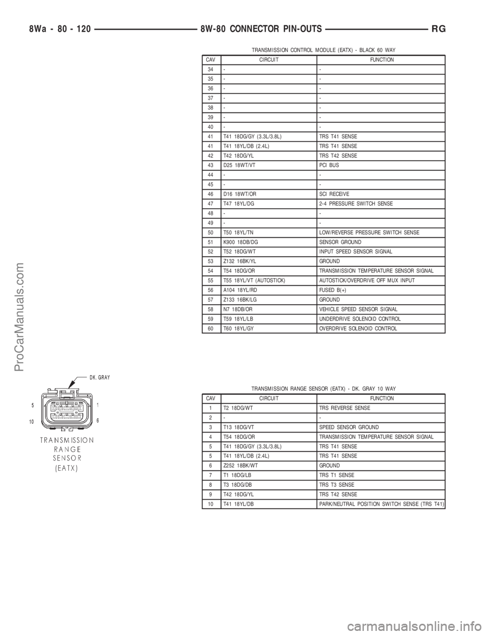
TRANSMISSION CONTROL MODULE (EATX) - BLACK 60 WAY
CAV CIRCUIT FUNCTION
34 - -
35 - -
36 - -
37 - -
38 - -
39 - -
40 - -
41 T41 18DG/GY (3.3L/3.8L) TRS T41 SENSE
41 T41 18YL/DB (2.4L) TRS T41 SENSE
42 T42 18DG/YL TRS T42 SENSE
43 D25 18WT/VT PCI BUS
44 - -
45 - -
46 D16 18WT/OR SCI RECEIVE
47 T47 18YL/DG 2-4 PRESSURE SWITCH SENSE
48 - -
49 - -
50 T50 18YL/TN LOW/REVERSE PRESSURE SWITCH SENSE
51 K900 18DB/DG SENSOR GROUND
52 T52 18DG/WT INPUT SPEED SENSOR SIGNAL
53 Z132 16BK/YL GROUND
54 T54 18DG/OR TRANSMISSION TEMPERATURE SENSOR SIGNAL
55 T55 18YL/VT (AUTOSTICK) AUTOSTICK/OVERDRIVE OFF MUX INPUT
56 A104 18YL/RD FUSED B(+)
57 Z133 16BK/LG GROUND
58 N7 18DB/OR VEHICLE SPEED SENSOR SIGNAL
59 T59 18YL/LB UNDERDRIVE SOLENOID CONTROL
60 T60 18YL/GY OVERDRIVE SOLENOID CONTROL
TRANSMISSION RANGE SENSOR (EATX) - DK. GRAY 10 WAY
CAV CIRCUIT FUNCTION
1 T2 18DG/WT TRS REVERSE SENSE
2- -
3 T13 18DG/VT SPEED SENSOR GROUND
4 T54 18DG/OR TRANSMISSION TEMPERATURE SENSOR SIGNAL
5 T41 18DG/GY (3.3L/3.8L) TRS T41 SENSE
5 T41 18YL/DB (2.4L) TRS T41 SENSE
6 Z252 18BK/WT GROUND
7 T1 18DG/LB TRS T1 SENSE
8 T3 18DG/DB TRS T3 SENSE
9 T42 18DG/YL TRS T42 SENSE
10 T41 18YL/DB PARK/NEUTRAL POSITION SWITCH SENSE (TRS T41)
8Wa - 80 - 120 8W-80 CONNECTOR PIN-OUTSRG
ProCarManuals.com
Page 1094 of 2321
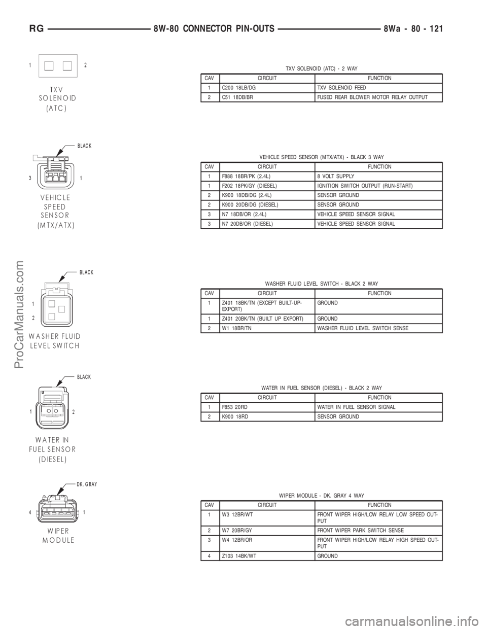
TXV SOLENOID (ATC)-2WAY
CAV CIRCUIT FUNCTION
1 C200 18LB/DG TXV SOLENOID FEED
2 C51 18DB/BR FUSED REAR BLOWER MOTOR RELAY OUTPUT
VEHICLE SPEED SENSOR (MTX/ATX) - BLACK 3 WAY
CAV CIRCUIT FUNCTION
1 F888 18BR/PK (2.4L) 8 VOLT SUPPLY
1 F202 18PK/GY (DIESEL) IGNITION SWITCH OUTPUT (RUN-START)
2 K900 18DB/DG (2.4L) SENSOR GROUND
2 K900 20DB/DG (DIESEL) SENSOR GROUND
3 N7 18DB/OR (2.4L) VEHICLE SPEED SENSOR SIGNAL
3 N7 20DB/OR (DIESEL) VEHICLE SPEED SENSOR SIGNAL
WASHER FLUID LEVEL SWITCH - BLACK 2 WAY
CAV CIRCUIT FUNCTION
1 Z401 18BK/TN (EXCEPT BUILT-UP-
EXPORT)GROUND
1 Z401 20BK/TN (BUILT UP EXPORT) GROUND
2 W1 18BR/TN WASHER FLUID LEVEL SWITCH SENSE
WATER IN FUEL SENSOR (DIESEL) - BLACK 2 WAY
CAV CIRCUIT FUNCTION
1 F853 20RD WATER IN FUEL SENSOR SIGNAL
2 K900 18RD SENSOR GROUND
WIPER MODULE - DK. GRAY 4 WAY
CAV CIRCUIT FUNCTION
1 W3 12BR/WT FRONT WIPER HIGH/LOW RELAY LOW SPEED OUT-
PUT
2 W7 20BR/GY FRONT WIPER PARK SWITCH SENSE
3 W4 12BR/OR FRONT WIPER HIGH/LOW RELAY HIGH SPEED OUT-
PUT
4 Z103 14BK/WT GROUND
RG8W-80 CONNECTOR PIN-OUTS8Wa - 80 - 121
ProCarManuals.com
Page 1432 of 2321
FUEL PUMP RELAY
DESCRIPTION
The fuel pump relay is located in the PDC. The
inside top of the PDC cover has a label showing relay
and fuse location.
OPERATION
The fuel pump relay supplies battery voltage to the
fuel pump. A buss bar in the Power Distribution Cen-
ter (PDC) supplies voltage to the solenoid side and
contact side of the relay. The fuel pump relay power
circuit contains a fuse between the buss bar in the
PDC and the relay. The fuse also protects the power
circuit for the Automatic Shutdown (ASD) relay. The
fuse is located in the PDC. Refer to the Wiring Dia-
grams for circuit information.
The PCM controls the fuel pump relay by switch-
ing the ground path for the solenoid side of the relay
on and off. The PCM turns the ground path off when
the ignition switch is in the Off position. When the
ignition switch is in the On position, the PCM ener-
gizes the fuel pump. If the crankshaft position sensor
does not detect engine rotation, the PCM de-ener-
gizes the relay after approximately one second.
IDLE AIR CONTROL MOTOR
DESCRIPTION
The idle air control motor is mounted on the throt-
tle body. The PCM operates the idle air control motor
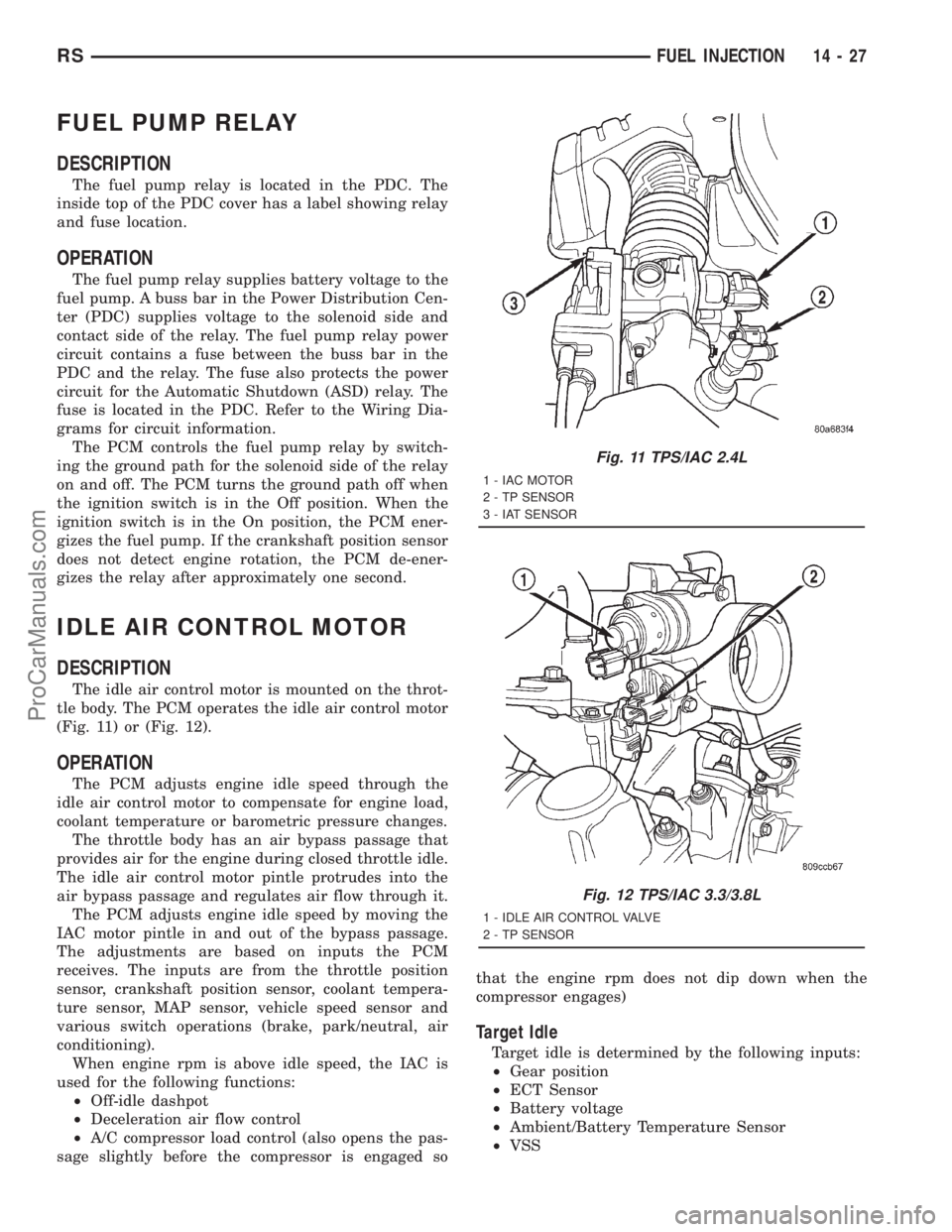
(Fig. 11) or (Fig. 12).
OPERATION
The PCM adjusts engine idle speed through the
idle air control motor to compensate for engine load,
coolant temperature or barometric pressure changes.
The throttle body has an air bypass passage that
provides air for the engine during closed throttle idle.
The idle air control motor pintle protrudes into the
air bypass passage and regulates air flow through it.
The PCM adjusts engine idle speed by moving the
IAC motor pintle in and out of the bypass passage.
The adjustments are based on inputs the PCM
receives. The inputs are from the throttle position
sensor, crankshaft position sensor, coolant tempera-
ture sensor, MAP sensor, vehicle speed sensor and
various switch operations (brake, park/neutral, air
conditioning).
When engine rpm is above idle speed, the IAC is
used for the following functions:
²Off-idle dashpot
²Deceleration air flow control
²A/C compressor load control (also opens the pas-
sage slightly before the compressor is engaged sothat the engine rpm does not dip down when the
compressor engages)
Target Idle
Target idle is determined by the following inputs:
²Gear position
²ECT Sensor
²Battery voltage
²Ambient/Battery Temperature Sensor
²VSS
Fig. 11 TPS/IAC 2.4L
1 - IAC MOTOR
2 - TP SENSOR
3 - IAT SENSOR
Fig. 12 TPS/IAC 3.3/3.8L
1 - IDLE AIR CONTROL VALVE
2 - TP SENSOR
RSFUEL INJECTION14-27
ProCarManuals.com
Page 1784 of 2321
TRANSMISSION CONTROL
RELAY
DESCRIPTION
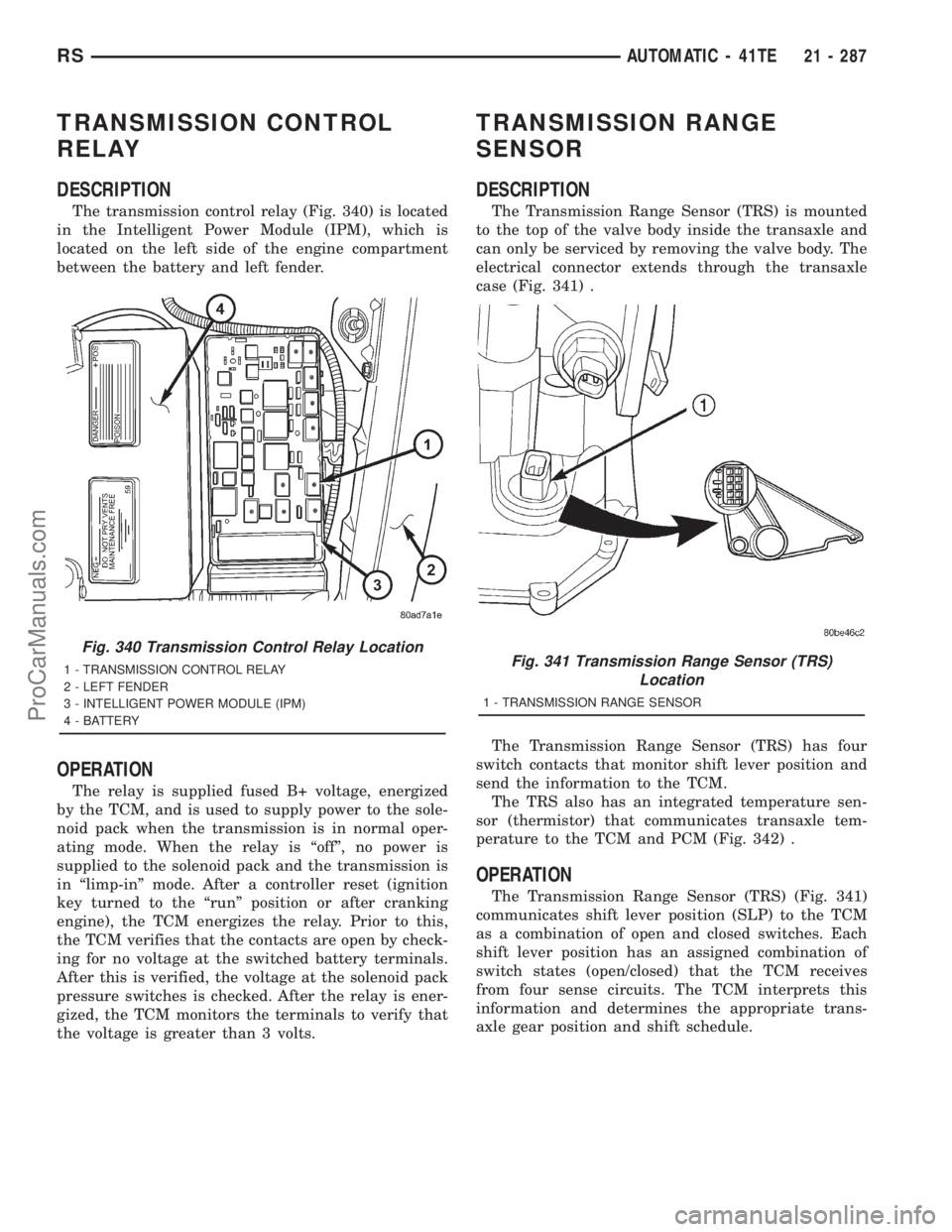
The transmission control relay (Fig. 340) is located
in the Intelligent Power Module (IPM), which is
located on the left side of the engine compartment
between the battery and left fender.
OPERATION
The relay is supplied fused B+ voltage, energized
by the TCM, and is used to supply power to the sole-
noid pack when the transmission is in normal oper-
ating mode. When the relay is ªoffº, no power is
supplied to the solenoid pack and the transmission is
in ªlimp-inº mode. After a controller reset (ignition
key turned to the ªrunº position or after cranking
engine), the TCM energizes the relay. Prior to this,
the TCM verifies that the contacts are open by check-
ing for no voltage at the switched battery terminals.
After this is verified, the voltage at the solenoid pack
pressure switches is checked. After the relay is ener-
gized, the TCM monitors the terminals to verify that
the voltage is greater than 3 volts.
TRANSMISSION RANGE
SENSOR
DESCRIPTION
The Transmission Range Sensor (TRS) is mounted
to the top of the valve body inside the transaxle and
can only be serviced by removing the valve body. The
electrical connector extends through the transaxle
case (Fig. 341) .
The Transmission Range Sensor (TRS) has four
switch contacts that monitor shift lever position and
send the information to the TCM.
The TRS also has an integrated temperature sen-
sor (thermistor) that communicates transaxle tem-
perature to the TCM and PCM (Fig. 342) .
OPERATION
The Transmission Range Sensor (TRS) (Fig. 341)
communicates shift lever position (SLP) to the TCM
as a combination of open and closed switches. Each
shift lever position has an assigned combination of
switch states (open/closed) that the TCM receives
from four sense circuits. The TCM interprets this
information and determines the appropriate trans-
axle gear position and shift schedule.
Fig. 340 Transmission Control Relay Location
1 - TRANSMISSION CONTROL RELAY
2 - LEFT FENDER
3 - INTELLIGENT POWER MODULE (IPM)
4 - BATTERYFig. 341 Transmission Range Sensor (TRS)
Location
1 - TRANSMISSION RANGE SENSOR
RSAUTOMATIC - 41TE21 - 287
ProCarManuals.com
Page 2176 of 2321
receptacles in the two lower finger formations of the
evaporator housing near the dash panel.
(5) Install and tighten the three screws that secure
the heater core shield to the left end of the heater/air
conditioner housing. Tighten the screws to 2 N´m (17
in. lbs.).
(6) Reinstall the silencer under the driver side end
of the instrument panel. (Refer to 23 - BODY/IN-
STRUMENT PANEL/INSTRUMENT PANEL
SILENCER - INSTALLATION).
(7) Reconnect the battery negative cable.
(8) Perform the heater-A/C control calibration pro-
cedure. (Refer to 24 - HEATING & AIR CONDITION-
ING/CONTROLS - FRONT/A/C-HEATER CONTROL
- STANDARD PROCEDURE - HEATER-A/C CON-
TROL CALIBRATION).
BLOWER MOTOR RELAY
DESCRIPTION
TERMINAL LEGEND
NUMBER IDENTIFICATION
30 COMMON FEED
85 COIL GROUND
86 COIL BATTERY
87 NORMALLY OPEN
87A NORMALLY CLOSED
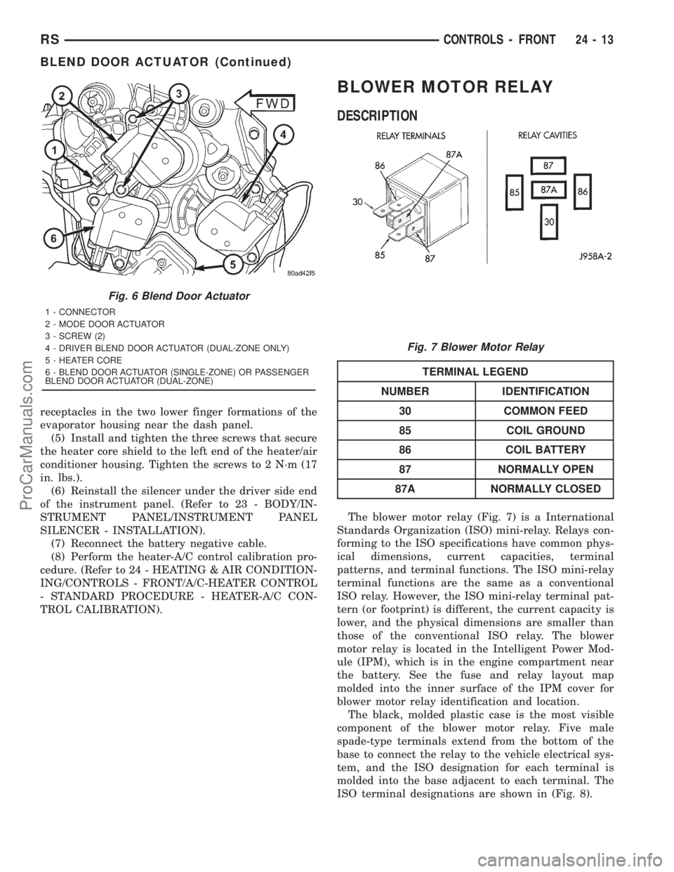
The blower motor relay (Fig. 7) is a International
Standards Organization (ISO) mini-relay. Relays con-
forming to the ISO specifications have common phys-
ical dimensions, current capacities, terminal
patterns, and terminal functions. The ISO mini-relay
terminal functions are the same as a conventional
ISO relay. However, the ISO mini-relay terminal pat-
tern (or footprint) is different, the current capacity is
lower, and the physical dimensions are smaller than
those of the conventional ISO relay. The blower
motor relay is located in the Intelligent Power Mod-
ule (IPM), which is in the engine compartment near
the battery. See the fuse and relay layout map
molded into the inner surface of the IPM cover for
blower motor relay identification and location.
The black, molded plastic case is the most visible
component of the blower motor relay. Five male
spade-type terminals extend from the bottom of the
base to connect the relay to the vehicle electrical sys-
tem, and the ISO designation for each terminal is
molded into the base adjacent to each terminal. The
ISO terminal designations are shown in (Fig. 8).
Fig. 6 Blend Door Actuator
1 - CONNECTOR
2 - MODE DOOR ACTUATOR
3 - SCREW (2)
4 - DRIVER BLEND DOOR ACTUATOR (DUAL-ZONE ONLY)
5 - HEATER CORE
6 - BLEND DOOR ACTUATOR (SINGLE-ZONE) OR PASSENGER
BLEND DOOR ACTUATOR (DUAL-ZONE)
Fig. 7 Blower Motor Relay
RSCONTROLS - FRONT24-13
BLEND DOOR ACTUATOR (Continued)
ProCarManuals.com