Page 1491 of 2321

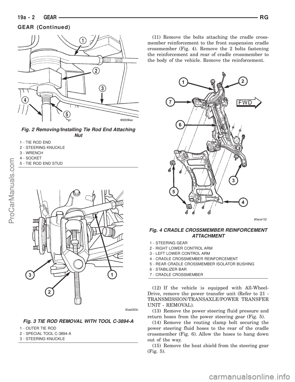
(11) Remove the bolts attaching the cradle cross-
member reinforcement to the front suspension cradle
crossmember (Fig. 4). Remove the 2 bolts fastening
the reinforcement and rear of cradle crossmember to
the body of the vehicle. Remove the reinforcement.
(12) If the vehicle is equipped with All-Wheel-
Drive, remove the power transfer unit (Refer to 21 -
TRANSMISSION/TRANSAXLE/POWER TRANSFER
UNIT - REMOVAL).
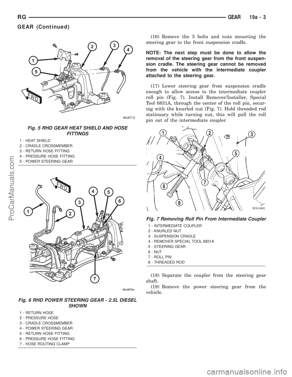
(13) Remove the power steering fluid pressure and
return hoses from the power steering gear (Fig. 5).
(14) Remove the routing clamp bolt securing the
power steering fluid hoses to the rear of the cradle
crossmember (Fig. 6). Allow the hoses to hang down
out of the way.
(15) Remove the heat shield from the steering gear
(Fig. 5).
Fig. 2 Removing/Installing Tie Rod End Attaching
Nut
1 - TIE ROD END
2 - STEERING KNUCKLE
3 - WRENCH
4 - SOCKET
5 - TIE ROD END STUD
Fig. 3 TIE ROD REMOVAL WITH TOOL C-3894-A
1 - OUTER TIE ROD
2 - SPECIAL TOOL C-3894-A
3 - STEERING KNUCKLE
Fig. 4 CRADLE CROSSMEMBER REINFORCEMENT
ATTACHMENT
1 - STEERING GEAR
2 - RIGHT LOWER CONTROL ARM
3 - LEFT LOWER CONTROL ARM
4 - CRADLE CROSSMEMBER REINFORCEMENT
5 - REAR CRADLE CROSSMEMBER ISOLATOR BUSHING
6 - STABILIZER BAR
7 - CRADLE CROSSMEMBER
19a - 2 GEARRG
GEAR (Continued)
ProCarManuals.com
Page 1492 of 2321

(16) Remove the 3 bolts and nuts mounting the
steering gear to the front suspension cradle.
NOTE: The next step must be done to allow the
removal of the steering gear from the front suspen-
sion cradle. The steering gear cannot be removed
from the vehicle with the intermediate coupler
attached to the steering gear.
(17) Lower steering gear from suspension cradle
enough to allow access to the intermediate coupler
roll pin (Fig. 7). Install Remover/Installer, Special
Tool 6831A, through the center of the roll pin, secur-
ing with the knurled nut (Fig. 7). Hold threaded rod
stationary while turning nut, this will pull the roll
pin out of the intermediate coupler.
(18) Separate the coupler from the steering gear
shaft.
(19) Remove the power steering gear from the
vehicle.
Fig. 5 RHD GEAR HEAT SHIELD AND HOSE
FITTINGS
1 - HEAT SHIELD
2 - CRADLE CROSSMEMBER
3 - RETURN HOSE FITTING
4 - PRESSURE HOSE FITTING
5 - POWER STEERING GEAR
Fig. 6 RHD POWER STEERING GEAR - 2.5L DIESEL
SHOWN
1 - RETURN HOSE
2 - PRESSURE HOSE
3 - CRADLE CROSSMEMBER
4 - POWER STEERING GEAR
5 - RETURN HOSE FITTING
6 - PRESSURE HOSE FITTING
7 - HOSE ROUTING CLAMP
Fig. 7 Removing Roll Pin From Intermediate Coupler
1 - INTERMEDIATE COUPLER
2 - KNURLED NUT
3 - SUSPENSION CRADLE
4 - REMOVER SPECIAL TOOL 6831A
5 - STEERING GEAR
6 - NUT
7 - ROLL PIN
8 - THREADED ROD
RGGEAR19a-3
GEAR (Continued)
ProCarManuals.com
Page 1493 of 2321

INSTALLATION - RHD GEAR
(1) Install the steering gear up in the front sus-
pension cradle crossmember, leaving room to install
intermediate coupler.
(2) Start the roll pin into the intermediate coupler
before installing coupler on steering gear shaft. Start
roll pin into coupler, using a hammer and tapping it
into the coupler. Then install the intermediate cou-
pler on the shaft of the steering gear.
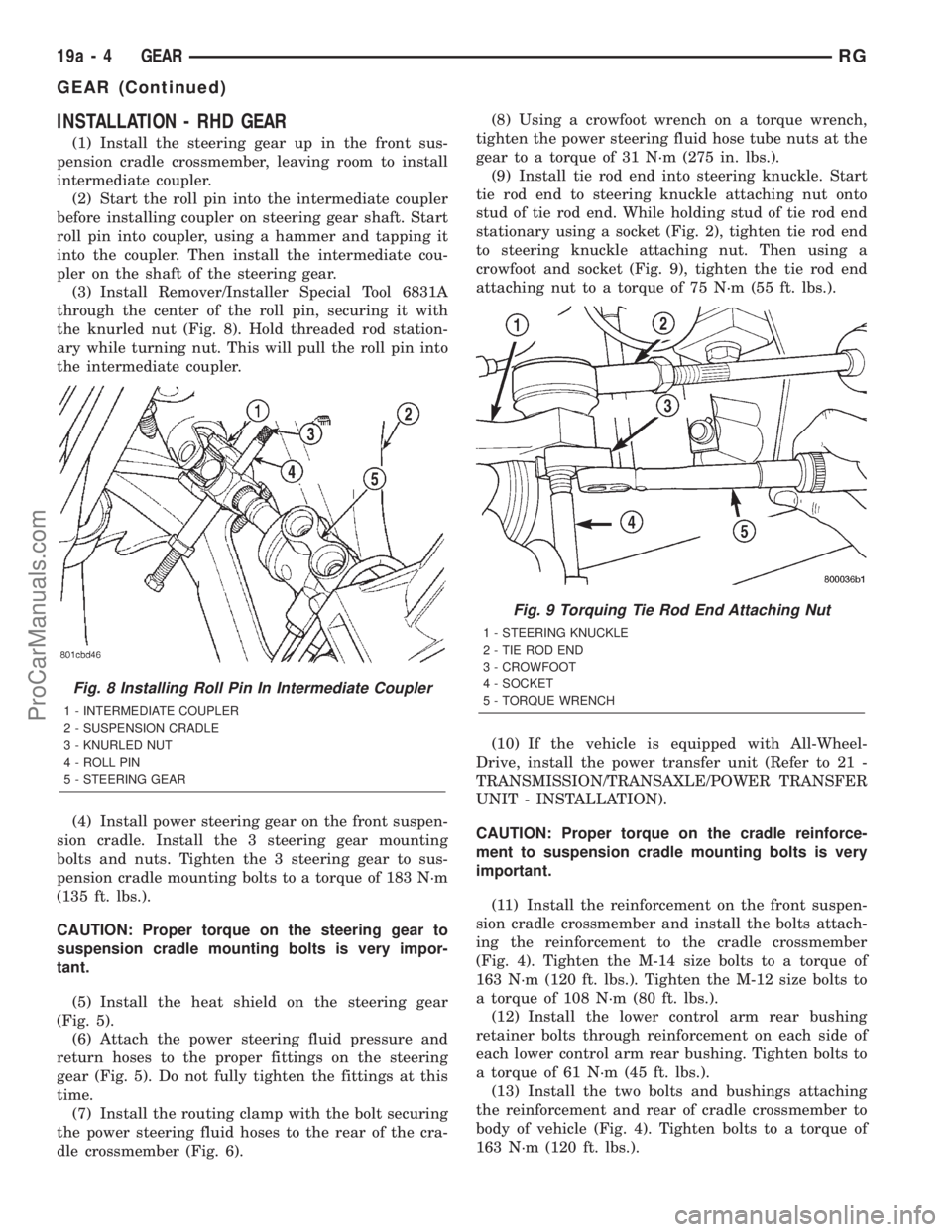
(3) Install Remover/Installer Special Tool 6831A
through the center of the roll pin, securing it with
the knurled nut (Fig. 8). Hold threaded rod station-
ary while turning nut. This will pull the roll pin into
the intermediate coupler.
(4) Install power steering gear on the front suspen-
sion cradle. Install the 3 steering gear mounting
bolts and nuts. Tighten the 3 steering gear to sus-
pension cradle mounting bolts to a torque of 183 N´m
(135 ft. lbs.).
CAUTION: Proper torque on the steering gear to
suspension cradle mounting bolts is very impor-
tant.
(5) Install the heat shield on the steering gear
(Fig. 5).
(6) Attach the power steering fluid pressure and
return hoses to the proper fittings on the steering
gear (Fig. 5). Do not fully tighten the fittings at this
time.
(7) Install the routing clamp with the bolt securing
the power steering fluid hoses to the rear of the cra-
dle crossmember (Fig. 6).(8) Using a crowfoot wrench on a torque wrench,
tighten the power steering fluid hose tube nuts at the
gear to a torque of 31 N´m (275 in. lbs.).
(9) Install tie rod end into steering knuckle. Start
tie rod end to steering knuckle attaching nut onto
stud of tie rod end. While holding stud of tie rod end
stationary using a socket (Fig. 2), tighten tie rod end
to steering knuckle attaching nut. Then using a
crowfoot and socket (Fig. 9), tighten the tie rod end
attaching nut to a torque of 75 N´m (55 ft. lbs.).
(10) If the vehicle is equipped with All-Wheel-
Drive, install the power transfer unit (Refer to 21 -
TRANSMISSION/TRANSAXLE/POWER TRANSFER
UNIT - INSTALLATION).
CAUTION: Proper torque on the cradle reinforce-
ment to suspension cradle mounting bolts is very
important.
(11) Install the reinforcement on the front suspen-
sion cradle crossmember and install the bolts attach-
ing the reinforcement to the cradle crossmember
(Fig. 4). Tighten the M-14 size bolts to a torque of
163 N´m (120 ft. lbs.). Tighten the M-12 size bolts to
a torque of 108 N´m (80 ft. lbs.).
(12) Install the lower control arm rear bushing
retainer bolts through reinforcement on each side of
each lower control arm rear bushing. Tighten bolts to
a torque of 61 N´m (45 ft. lbs.).
(13) Install the two bolts and bushings attaching
the reinforcement and rear of cradle crossmember to
body of vehicle (Fig. 4). Tighten bolts to a torque of
163 N´m (120 ft. lbs.).
Fig. 8 Installing Roll Pin In Intermediate Coupler
1 - INTERMEDIATE COUPLER
2 - SUSPENSION CRADLE
3 - KNURLED NUT
4 - ROLL PIN
5 - STEERING GEAR
Fig. 9 Torquing Tie Rod End Attaching Nut
1 - STEERING KNUCKLE
2 - TIE ROD END
3 - CROWFOOT
4 - SOCKET
5 - TORQUE WRENCH
19a - 4 GEARRG
GEAR (Continued)
ProCarManuals.com
Page 1956 of 2321
SUSPENSION HANGER REINFORCEMENTS - LONG WHEEL BASE ONLY
FRONT HINGE PILLAR REINFORCEMENTS - LONG WHEEL BASE ONLY
RSBODY23-43
BODY (Continued)
ProCarManuals.com
Page 1963 of 2321
SUSPENSION RETAINERS AND REINFORCEMENTS - RIGHT
23 - 50 BODYRS
BODY (Continued)
ProCarManuals.com
Page 1965 of 2321
SUSPENSION RETAINERS AND REINFORCEMENTS - LEFT
23 - 52 BODYRS
BODY (Continued)
ProCarManuals.com
Page 1967 of 2321
REAR SUSPENSION BRACKETS
23 - 54 BODYRS
BODY (Continued)
ProCarManuals.com
Page 1971 of 2321
FUEL TANK MOUNTING/REAR SEAT AND SUSPENSION
23 - 58 BODYRS
BODY (Continued)
ProCarManuals.com