2001 DODGE RAM service reset
[x] Cancel search: service resetPage 667 of 2889
OPERATION
When the power lumbar switch paddle is actuated,
a battery feed and a ground path are applied through
the switch contacts to the power lumbar adjuster
motor. The motor operates to move the lumbar
adjuster through its drive unit in the selected direc-
tion until the switch is released, or until the travel
limit of the adjuster is reached. When the switch is
moved in the opposite direction, the battery feed and
ground path to the motor are reversed through the
switch contacts. This causes the motor to run in the
opposite direction.
The power lumbar switch should not be held
applied in either direction after the adjuster has
reached its travel limit. The power lumbar adjuster
motor contains a self-resetting circuit breaker to pro-
tect it from overload. However, consecutive or fre-
quent resetting of the circuit breaker must not be
allowed to continue, or the motor may be damaged.
REMOVAL
The power lumbar switch is integral with the other
power seat switches. Refer to the appropriate driver
or passenger power front seat switch removal and/or
installation procedure.
LUMBAR MOTOR
DESCRIPTION
The 8-way power seat option includes an electri-
cally operated lumbar support mechanism. The only
visible evidence of this option is the separate power
lumbar switch control paddle that is located on the
outboard seat cushion side shield, next to the other
power seat switch control knobs. The power lumbar
adjuster and motor are concealed beneath the seat
back trim cover and padding, where they are secured
to a molded plastic back panel and to the seat back
frame.
The power lumbar adjuster cannot be repaired, and
is serviced only as a unit with the seat back frame. If
the power lumbar adjuster or the seat back frame
are damaged or faulty, the entire seat back frame
unit must be replaced. Refer toBucket Seat Back
in Body for the seat back frame service procedures.
OPERATION
The power lumbar adjuster mechanism includes a
reversible electric motor that is secured to the
inboard side of the seat back panel and is connected
to a worm-drive gearbox. The motor and gearbox
operate the lumbar adjuster mechanism in the center
of the seat back by extending and retracting a cable
that actuates a lever. The action of this lever com-
presses or relaxes a grid of flexible slats. The morethis grid is compressed, the more the slats bow out-
ward against the center of the seat back padding,
providing additional lumbar support.
DIAGNOSIS & TESTING - POWER LUMBAR
ADJUSTER
Actuate the power lumbar switch to move the
power lumbar adjuster in each direction. The power
lumbar adjuster should move in both directions. It
should be noted that the power lumber adjuster nor-
mally operates very quietly and exhibits little visible
movement. If the power lumbar adjuster fails to oper-
ate in only one direction, move the adjuster a short
distance in the opposite direction and test again to be
certain that the adjuster is not at its travel limit. If
the power lumbar adjuster still fails to operate in
only one direction, refer toPower Lumbar Switch
in the Diagnosis and Testing section of this group. If
the power lumbar adjuster fails to operate in either
direction, perform the following tests. For complete
circuit diagrams, refer toPower Seatin Wiring Dia-
grams.
(1) Check the power seat circuit breaker in the
junction block. If OK, go to Step 2. If not OK, replace
the faulty power seat circuit breaker.
(2) Check for battery voltage at the power seat cir-
cuit breaker in the junction block. If OK, go to Step
3. If not OK, repair the open fused B(+) circuit to the
fuse in the Power Distribution Center as required.
(3) Remove the outboard seat cushion side shield
from the seat. Disconnect the seat wire harness con-
nector from the power lumbar switch connector
receptacle. Check for battery voltage at the fused
B(+) circuit cavity of the power seat wire harness
connector for the power lumbar switch. If OK, go to
Step 4. If not OK, repair the open fused B(+) circuit
to the power seat circuit breaker in the junction
block as required.
(4) Check for continuity between the ground cir-
cuit cavity of the power seat wire harness connector
for the power lumbar switch and a good ground.
There should be continuity. If OK, go to Step 5. If not
OK, repair the open ground circuit to ground as
required.
(5) Test the power lumbar switch. Refer toPower
Lumbar Switchin the Diagnosis and Testing sec-
tion of this group. If the switch tests OK, test the cir-
cuits of the power seat wire harness between the
power lumbar adjuster motor and the power lumbar
switch for shorts or opens. If the circuits check OK,
replace the faulty seat back frame assembly. If the
circuits are not OK, repair the power seat wire har-
ness as required.
8N - 18 POWER SEAT SYSTEMBR/BE
LUMBAR CONTROL SWITCH (Continued)
Page 670 of 2889
the motor and drive unit of the power seat recliner
mechanism is secured with two screws to the seat
cushion frame, and is concealed by the outboard seat
cushion side shield.
The power seat recliner cannot be repaired. If the
unit is faulty or damaged, it must be replaced. Refer
toBucket Seat Reclinerin Body for the service
procedure.
OPERATION
The power seat recliner includes a reversible elec-
tric motor that is secured to the lower hinge plate of
the recliner unit. The motor is connected to a gearbox
that moves the upper hinge plate of the power seat
recliner through a screw-type drive unit.
DIAGNOSIS & TESTING - POWER SEAT
RECLINER
Following are tests that will help to diagnose the
hard wired components and circuits of the power seat
system. Actuate the power seat recliner switch to
move the power seat recliner adjuster in each direc-
tion. The power seat recliner adjuster should move in
both directions. If the power seat recliner adjuster
fails to operate in only one direction, move the
adjuster a short distance in the opposite direction
and test again to be certain that the adjuster is not
at its travel limit. If the power seat recliner adjuster
still fails to operate in only one direction, refer to
Power Seat Switchin the Diagnosis and Testing
section of this group. If the power recliner adjuster
fails to operate in either direction, perform the fol-
lowing tests. For complete circuit diagrams, refer to
Power Seatin Wiring Diagrams.
(1) Check the power seat circuit breaker in the
junction block. If OK, go to Step 2. If not OK, replace
the faulty power seat circuit breaker.
(2) Check for battery voltage at the power seat cir-
cuit breaker in the junction block. If OK, go to Step
3. If not OK, repair the open fused B(+) circuit to the
fuse in the Power Distribution Center as required.
(3) Remove the outboard seat cushion side shield
from the seat. Disconnect the seat wire harness con-
nector from the power seat switch connector recepta-
cle. Check for battery voltage at the fused B(+)
circuit cavity of the power seat wire harness connec-
tor for the power seat switch. If OK, go to Step 4. If
not OK, repair the open fused B(+) circuit to the
power seat circuit breaker in the junction block as
required.
(4) Check for continuity between the ground cir-
cuit cavity of the power seat wire harness connector
for the power seat switch and a good ground. There
should be continuity. If OK, go to Step 5. If not OK,
repair the open ground circuit to ground as required.(5) Test the power seat switch. Refer toPower
Seat Switchin the Diagnosis and Testing section of
this group. If the switch tests OK, test the circuits of
the power seat wire harness between the power seat
recliner adjuster motor and the power seat switch for
shorts or opens. If the circuits check OK, replace the
faulty power seat recliner unit. If the circuits are not
OK, repair the power seat wire harness as required.
POWER SEAT TRACK
DESCRIPTION
There are three reversible motors that operate the
power seat adjuster. The motors are connected to
worm-drive gearboxes that move the seat adjuster
through a combination of screw-type drive units.
The front and rear of a seat are operated by differ-
ent motors. They can be raised or lowered indepen-
dently of each other. When the center seat switch is
pushed in the Up or Down direction, both the front
and rear motors operate in unison. On standard cab
models the entire seat is moved up or down, on
extended cab models (club cab and quad cab) the seat
cushion moves independently of the seat back in the
up or down directions. The forward-rearward motor
is operated by pushing the center seat switch in the
Forward or Rearward direction, which moves the
entire seat in the selected direction on all models.
Each motor contains a self-resetting circuit breaker
to protect it from overload. Consecutive or frequent
resetting of the circuit breakers must not be allowed
to continue, or the motors may be damaged. Make
the necessary repairs.
The power seat adjuster and motors cannot be
repaired, and are serviced only as a complete unit. If
any component in this unit is faulty or damaged, the
entire power seat adjuster and motors assembly must
be replaced.
OPERATION
When a power seat switch is actuated, a battery
feed and a ground path are applied through the
switch contacts to the motor(s). The motor(s) and
drive unit(s) operate to move the seat in the selected
direction until the switch is released, or until the
travel limit of the power seat adjuster is reached.
When the switch is moved in the opposite direction,
the battery feed and ground path to the motor(s) are
reversed through the switch contacts. This causes the
motor to run in the opposite direction.
DIAGNOSIS & TESTING - POWER SEAT TRACK
For circuit descriptions and diagrams, refer to Wir-
ing Diagrams.
BR/BEPOWER SEAT SYSTEM 8N - 21
RECLINER MOTOR (Continued)
Page 675 of 2889
INSTALLATION
(1) Connect the power window switch to the har-
ness connector.
(2) Insert the rear of the switch and bezel unit into
the opening.
(3) Push down on the front of the switch until the
retaining tabs snap into place.
(4) Reconnect the battery negative cable.
WINDOW MOTOR
DESCRIPTION
A permanent magnet reversible motor moves the
window regulator through an integral gearbox mech-
anism. A positive and negative battery connection to
the two motor terminals will cause the motor to
rotate in one direction. Reversing the current
through these same two connections will cause the
motor to rotate in the opposite direction.
In addition, each power window motor is equipped
with an integral self-resetting circuit breaker to pro-
tect the motor from overloads. The power window
motor and gearbox assembly cannot be repaired and,
if faulty or damaged, the entire power window regu-
lator assembly must be replaced.
DIAGNOSIS AND TESTING - WINDOW MOTOR
For circuit descriptions and diagrams, refer to the
appropriate wiring information. The wiring informa-
tion includes wiring diagrams, proper wire and con-
nector repair procedures, details of wire harness
routing and retention, connector pin-out information
and location views for the various wire harness con-
nectors, splices and grounds. Before you proceed withthis diagnosis, confirm proper switch operation.
(Refer to 8 - ELECTRICAL/POWER WINDOWS/
POWER WINDOW SWITCH - DIAGNOSIS AND
TESTING).
(1) Disconnect and isolate the battery negative
cable. Remove the trim panel from the door with the
inoperative power window.
(2) Unplug the power window motor wire harness
connector. Apply 12 volts across the motor terminals
to check its operation in one direction. Reverse the
connections across the motor terminals to check the
operation in the other direction. Remember, if the
window is in the full up or full down position, the
motor will not operate in that direction by design. If
OK, repair the circuits from the power window motor
to the power window switch as required. If not OK,
replace the faulty motor.
(3) If the motor operates in both directions, check
the operation of the window glass and lift mechanism
through its complete up and down travel. There
should be no binding or sticking of the window glass
or lift mechanism through the entire travel range. If
not OK, (Refer to 23 - BODY/DOOR - FRONT/WIN-
DOW REGULATOR - REMOVAL).
REMOVAL
The power window motor and mechanism is inte-
gral to the power window regulator unit. If the power
window motor or mechanism is faulty or damaged,
the entire power window regulator unit must be
replaced. (Refer to 23 - BODY/DOOR - FRONT/WIN-
DOW REGULATOR - REMOVAL) for the window
regulator service procedures.
8N - 26 POWER WINDOWSBR/BE
POWER WINDOW SWITCH (Continued)
Page 1136 of 2889
8W-97 POWER DISTRIBUTION
TABLE OF CONTENTS
page page
POWER DISTRIBUTION
DESCRIPTION............................1
OPERATION.............................1
SPECIAL TOOLS..........................2
CIGAR LIGHTER OUTLET
DESCRIPTION............................2
OPERATION.............................2
DIAGNOSIS AND TESTING..................2
CIGAR LIGHTER........................2
REMOVAL...............................3
INSTALLATION............................3
CIRCUIT BREAKER
DESCRIPTION............................4
DIAGNOSIS AND TESTING..................4
CIRCUIT BREAKER......................4
GENERATOR CARTRIDGE FUSE
DESCRIPTION............................4
OPERATION.............................4
REMOVAL...............................4
INSTALLATION............................4
IOD FUSE
DESCRIPTION............................4OPERATION.............................5
REMOVAL...............................5
INSTALLATION............................5
JUNCTION BLOCK
DESCRIPTION............................6
OPERATION.............................6
REMOVAL...............................6
INSTALLATION............................7
POWER DISTRIBUTION CENTER
DESCRIPTION............................7
OPERATION.............................8
REMOVAL...............................8
INSTALLATION............................8
POWER OUTLET
DESCRIPTION............................9
OPERATION.............................10
DIAGNOSIS AND TESTING.................10
POWER OUTLET.......................10
REMOVAL..............................10
INSTALLATION...........................11
POWER DISTRIBUTION
DESCRIPTION
This group covers the various standard and
optional power distribution components used on this
model. The power distribution system for this vehicle
consists of the following components:
²Power Distribution Center (PDC)
²Junction Block (JB).
The power distribution system also incorporates
various types of circuit control and protection fea-
tures, including:
²Automatic resetting circuit breakers
²Blade-type fuses
²Cartridge fuses
²Circuit splice blocks
²Flashers
²Relays.
Following are general descriptions of the major
components in the power distribution system. See the
owner's manual in the vehicle glove box for more
information on the features and use of all of thepower distribution system components. Refer to the
index in this service manual for the location of com-
plete circuit diagrams for the various power distribu-
tion system components.
OPERATION
The power distribution system for this vehicle is
designed to provide safe, reliable, and centralized dis-
tribution points for the electrical current required to
operate all of the many standard and optional facto-
ry-installed electrical and electronic powertrain,
chassis, safety, security, comfort and convenience sys-
tems. At the same time, the power distribution sys-
tem was designed to provide ready access to these
electrical distribution points for the vehicle techni-
cian to use when conducting diagnosis and repair of
faulty circuits. The power distribution system can
also prove useful for the sourcing of additional elec-
trical circuits that may be required to provide the
electrical current needed to operate many accessories
that the vehicle owner may choose to have installed
in the aftermarket.
BR/BE8W-97 POWER DISTRIBUTION 8W - 97 - 1
Page 1139 of 2889
(5) Install the cigar lighter knob and element into
the cigar lighter receptacle base, or the protective cap
into the power outlet receptacle base.
(6) Reconnect the battery negative cable.
CIRCUIT BREAKER
DESCRIPTION
An automatic resetting circuit breaker in the junc-
tion block is used to protect the system from a short
circuit, or from an overload condition caused by an
obstructed or stuck seat adjuster.
The circuit breaker cannot be repaired and, if
faulty or damaged, it must be replaced.
DIAGNOSIS & TESTING - CIRCUIT BREAKER
For circuit descriptions and diagrams, refer to Wir-
ing Diagrams.
(1) Locate the correct circuit breaker in the junc-
tion block. Pull out the circuit breaker slightly, but
be certain that the circuit breaker terminals still con-
tact the terminals in the junction block cavities.
(2) Connect the negative lead of a 12-volt DC volt-
meter to a good ground.
(3) With the voltmeter positive lead, check both
terminals of the circuit breaker for battery voltage.
If only one terminal has battery voltage, the circuit
breaker is faulty and must be replaced. If neither ter-
minal has battery voltage, repair the open circuit
from the Power Distribution Center (PDC) as
required.
GENERATOR CARTRIDGE
FUSE
DESCRIPTION
A 140 ampere generator cartridge fuse is used on
this model. The generator cartridge fuse is similar to
other cartridge fuses found in the Power Distribution
Center (PDC). This fuse has a color-coded plastic
housing and a clear plastic fuse conductor inspection
cover like other cartridge fuses, but has a higher cur-
rent rating and is connected and secured with screws
instead of being pushed onto male spade-type termi-
nals. The generator cartridge fuse cannot be repaired
and, if faulty or damaged, it must be replaced.
OPERATION
The generator cartridge fuse is secured between
the two B(+) terminal stud connection bus bars
within the Power Distribution Center (PDC). This
fuse protects the vehicle electrical system from dam-
age that could be caused by excessive charging sys-
tem output and/or excessive electrical system currentlevels resulting from a faulty generator or faulty
charging system control circuits. If the current rating
of the fuse is exceeded, the fuse conductor melts to
open the generator output circuit connection to the
PDC. If a generator cartridge fuse fails, be certain to
completely inspect and test the vehicle charging sys-
tem before replacing the fuse and returning the vehi-
cle to service. Refer toCharging Systemin the
index of this service manual for the charging system
diagnostic procedures. Refer toPower Distribution
in the index of this service manual for the location of
complete PDC circuit diagrams.
REMOVAL
If a generator cartridge fuse fails, be certain to
inspect and test the vehicle charging system before
replacing the cartridge fuse and returning the vehicle
to service. Refer toCharging Systemin the index of
this service manual for the charging system diagnos-
tic procedures.
(1) Disconnect and isolate the battery negative
cable.
(2) Unlatch and remove the cover from the Power
Distribution Center (PDC).
(3) Remove the two screws that secure the genera-
tor cartridge fuse to the two B(+) terminal stud bus
bars within the PDC.
(4) Remove the generator cartridge fuse from the
PDC.
INSTALLATION
If a generator cartridge fuse fails, be certain to
inspect and test the vehicle charging system before
replacing the cartridge fuse and returning the vehicle
to service. Refer toCharging Systemin the index of
this service manual for the charging system diagnos-
tic procedures.
(1) Position the generator cartridge fuse onto the
two B(+) terminal stud bus bars within the PDC.
(2) Install and tighten the two screws that secure
the generator cartridge fuse to the two B(+) terminal
stud bus bars within the PDC. Tighten the screws to
3.4 N´m (30 in. lbs.).Be certain that both screws
are tightened to the proper torque value.
(3) Install and latch the cover onto the PDC.
(4) Reconnect the battery negative cable.
IOD FUSE
DESCRIPTION
All vehicles are equipped with an Ignition-Off
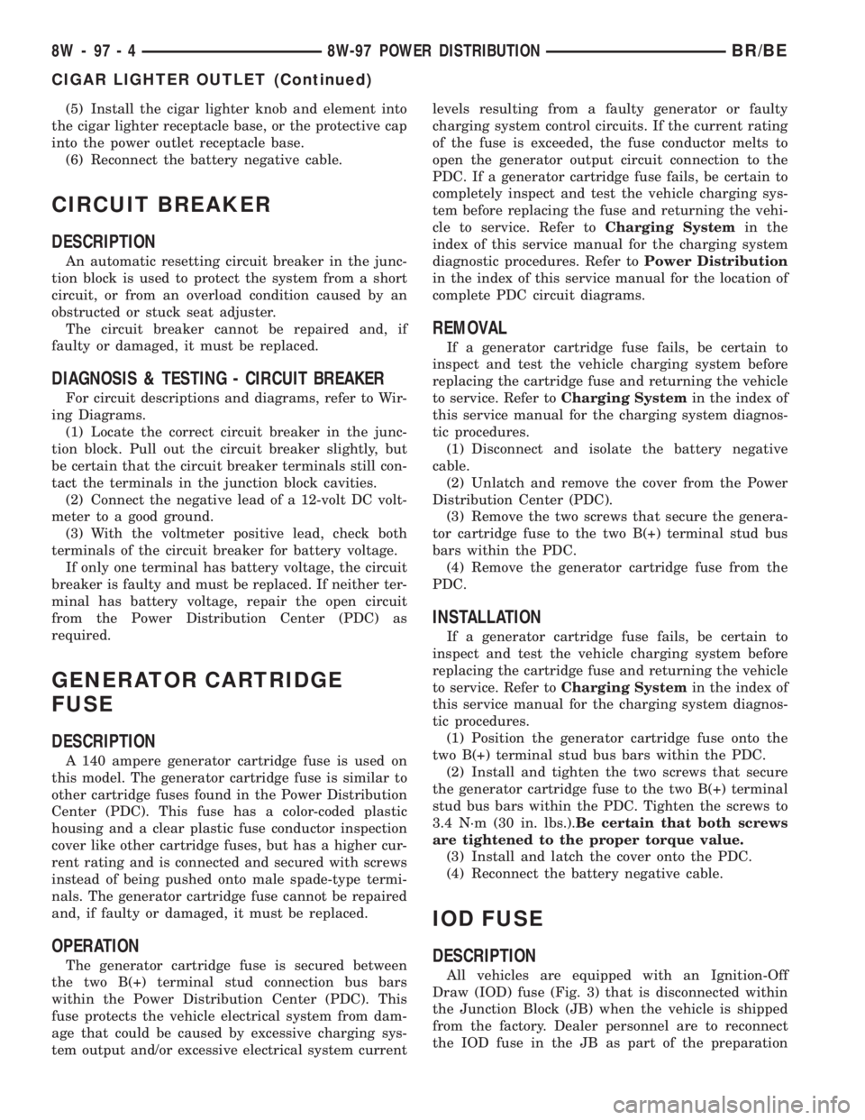
Draw (IOD) fuse (Fig. 3) that is disconnected within
the Junction Block (JB) when the vehicle is shipped
from the factory. Dealer personnel are to reconnect
the IOD fuse in the JB as part of the preparation
8W - 97 - 4 8W-97 POWER DISTRIBUTIONBR/BE
CIGAR LIGHTER OUTLET (Continued)
Page 1141 of 2889
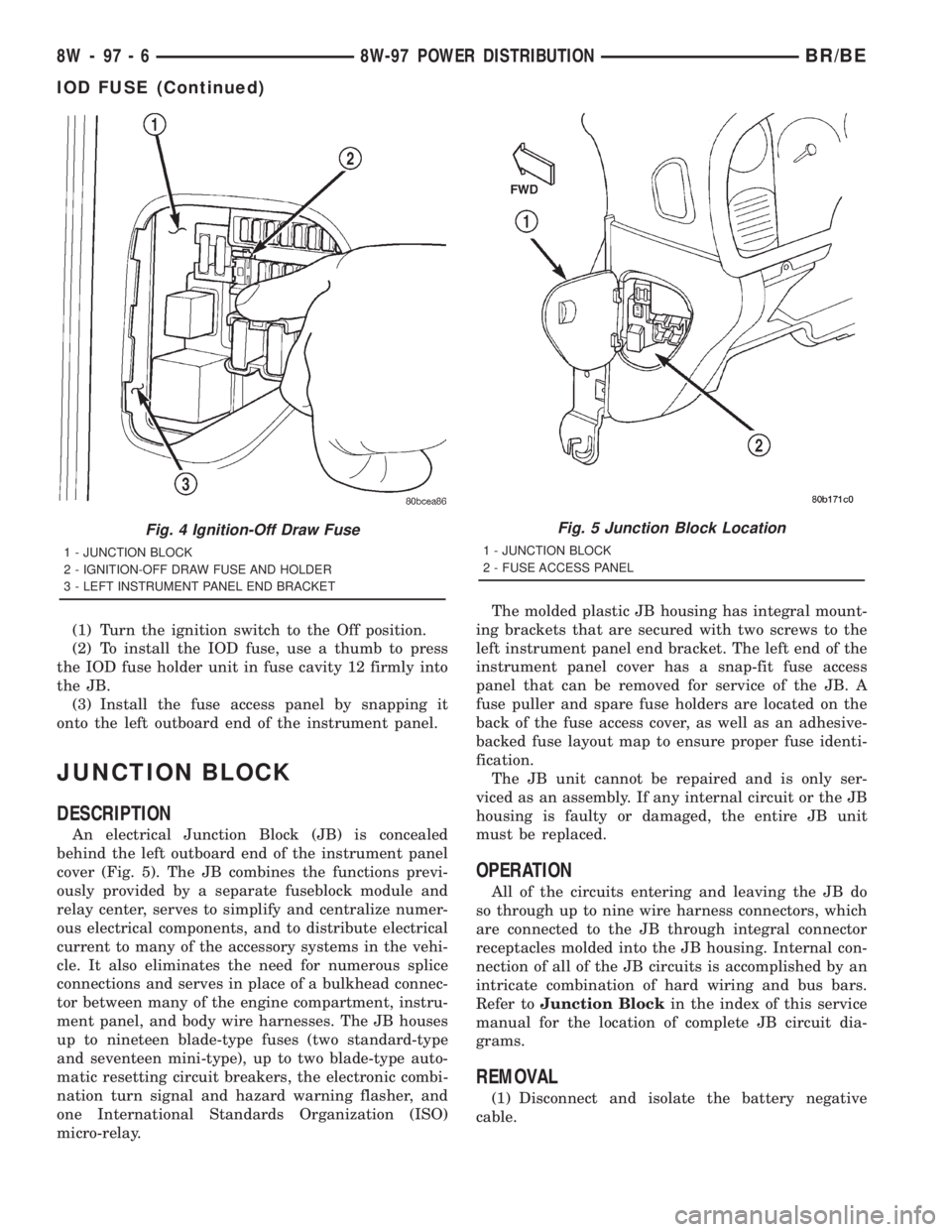
(1) Turn the ignition switch to the Off position.
(2) To install the IOD fuse, use a thumb to press
the IOD fuse holder unit in fuse cavity 12 firmly into
the JB.
(3) Install the fuse access panel by snapping it
onto the left outboard end of the instrument panel.
JUNCTION BLOCK
DESCRIPTION
An electrical Junction Block (JB) is concealed
behind the left outboard end of the instrument panel
cover (Fig. 5). The JB combines the functions previ-
ously provided by a separate fuseblock module and
relay center, serves to simplify and centralize numer-
ous electrical components, and to distribute electrical
current to many of the accessory systems in the vehi-
cle. It also eliminates the need for numerous splice
connections and serves in place of a bulkhead connec-
tor between many of the engine compartment, instru-
ment panel, and body wire harnesses. The JB houses
up to nineteen blade-type fuses (two standard-type
and seventeen mini-type), up to two blade-type auto-
matic resetting circuit breakers, the electronic combi-
nation turn signal and hazard warning flasher, and
one International Standards Organization (ISO)
micro-relay.The molded plastic JB housing has integral mount-
ing brackets that are secured with two screws to the
left instrument panel end bracket. The left end of the
instrument panel cover has a snap-fit fuse access
panel that can be removed for service of the JB. A
fuse puller and spare fuse holders are located on the
back of the fuse access cover, as well as an adhesive-
backed fuse layout map to ensure proper fuse identi-
fication.
The JB unit cannot be repaired and is only ser-
viced as an assembly. If any internal circuit or the JB
housing is faulty or damaged, the entire JB unit
must be replaced.
OPERATION
All of the circuits entering and leaving the JB do
so through up to nine wire harness connectors, which
are connected to the JB through integral connector
receptacles molded into the JB housing. Internal con-
nection of all of the JB circuits is accomplished by an
intricate combination of hard wiring and bus bars.
Refer toJunction Blockin the index of this service
manual for the location of complete JB circuit dia-
grams.
REMOVAL
(1) Disconnect and isolate the battery negative
cable.
Fig. 4 Ignition-Off Draw Fuse
1 - JUNCTION BLOCK
2 - IGNITION-OFF DRAW FUSE AND HOLDER
3 - LEFT INSTRUMENT PANEL END BRACKET
Fig. 5 Junction Block Location
1 - JUNCTION BLOCK
2 - FUSE ACCESS PANEL
8W - 97 - 6 8W-97 POWER DISTRIBUTIONBR/BE
IOD FUSE (Continued)
Page 1405 of 2889
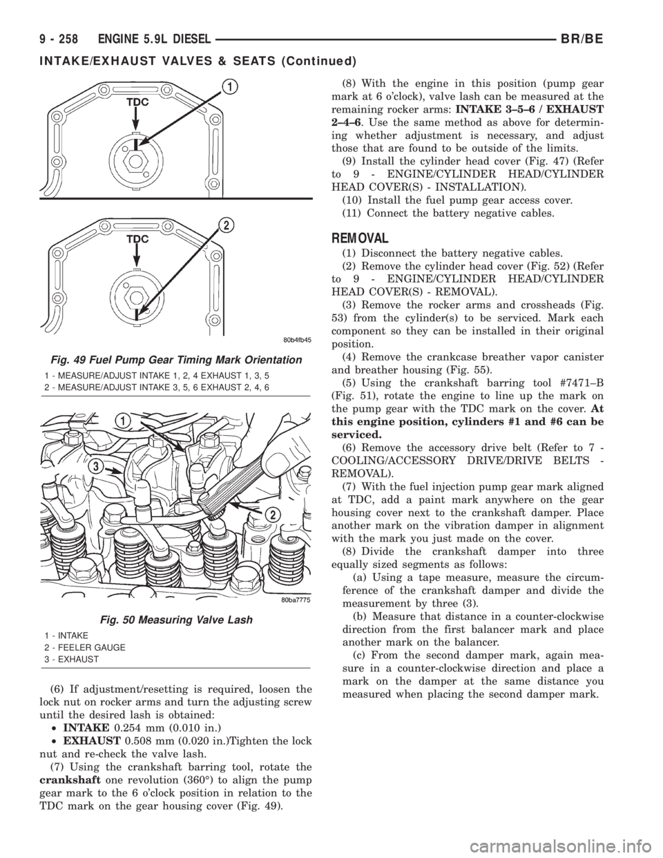
(6) If adjustment/resetting is required, loosen the
lock nut on rocker arms and turn the adjusting screw
until the desired lash is obtained:
²INTAKE0.254 mm (0.010 in.)
²EXHAUST0.508 mm (0.020 in.)Tighten the lock
nut and re-check the valve lash.
(7) Using the crankshaft barring tool, rotate the
crankshaftone revolution (360É) to align the pump
gear mark to the 6 o'clock position in relation to the
TDC mark on the gear housing cover (Fig. 49).(8) With the engine in this position (pump gear
mark at 6 o'clock), valve lash can be measured at the
remaining rocker arms:INTAKE 3±5±6 / EXHAUST
2±4±6. Use the same method as above for determin-
ing whether adjustment is necessary, and adjust
those that are found to be outside of the limits.
(9) Install the cylinder head cover (Fig. 47) (Refer
to 9 - ENGINE/CYLINDER HEAD/CYLINDER
HEAD COVER(S) - INSTALLATION).
(10) Install the fuel pump gear access cover.
(11) Connect the battery negative cables.
REMOVAL
(1) Disconnect the battery negative cables.
(2) Remove the cylinder head cover (Fig. 52) (Refer
to 9 - ENGINE/CYLINDER HEAD/CYLINDER
HEAD COVER(S) - REMOVAL).
(3) Remove the rocker arms and crossheads (Fig.
53) from the cylinder(s) to be serviced. Mark each
component so they can be installed in their original
position.
(4) Remove the crankcase breather vapor canister
and breather housing (Fig. 55).
(5) Using the crankshaft barring tool #7471±B
(Fig. 51), rotate the engine to line up the mark on
the pump gear with the TDC mark on the cover.At
this engine position, cylinders #1 and #6 can be
serviced.
(6) Remove the accessory drive belt (Refer to 7 -
COOLING/ACCESSORY DRIVE/DRIVE BELTS -
REMOVAL).
(7) With the fuel injection pump gear mark aligned
at TDC, add a paint mark anywhere on the gear
housing cover next to the crankshaft damper. Place
another mark on the vibration damper in alignment
with the mark you just made on the cover.
(8) Divide the crankshaft damper into three
equally sized segments as follows:
(a) Using a tape measure, measure the circum-
ference of the crankshaft damper and divide the
measurement by three (3).
(b) Measure that distance in a counter-clockwise
direction from the first balancer mark and place
another mark on the balancer.
(c) From the second damper mark, again mea-
sure in a counter-clockwise direction and place a
mark on the damper at the same distance you
measured when placing the second damper mark.
Fig. 49 Fuel Pump Gear Timing Mark Orientation
1 - MEASURE/ADJUST INTAKE 1, 2, 4 EXHAUST 1, 3, 5
2 - MEASURE/ADJUST INTAKE 3, 5, 6 EXHAUST 2, 4, 6
Fig. 50 Measuring Valve Lash
1 - INTAKE
2 - FEELER GAUGE
3 - EXHAUST
9 - 258 ENGINE 5.9L DIESELBR/BE
INTAKE/EXHAUST VALVES & SEATS (Continued)
Page 2832 of 2889
INSPECTION - BATTERY
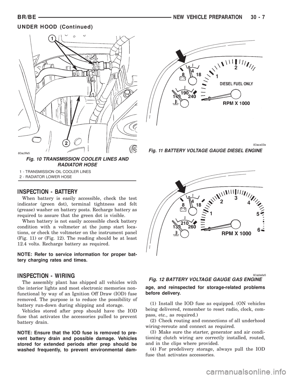
When battery is easily accessible, check the test
indicator (green dot), terminal tightness and felt
(grease) washer on battery posts. Recharge battery as
required to assure that the green dot is visible.
When battery is not easily accessible check battery
condition with a voltmeter at the jump start loca-
tions, or check the voltmeter on the instrument panel
(Fig. 11) or (Fig. 12). The reading should be at least
12.4 volts. Recharge battery as required.
NOTE: Refer to service information for proper bat-
tery charging rates and times.
INSPECTION - WIRING
The assembly plant has shipped all vehicles with
the interior lights and most electronic memories non-
functional by way of an Ignition Off Draw (IOD) fuse
removed. The purpose is to reduce the possibility of
battery run-down during shipping and storage.
Vehicles stored after prep should have the IOD
fuse that activates the accessories pulled to prevent
battery drain.
NOTE: Ensure that the IOD fuse is removed to pre-
vent battery drain and possible damage. Vehicles
stored for extended periods after prep should be
washed frequently, to prevent environmental dam-age, and reinspected for storage-related problems
before delivery.
(1) Install the IOD fuse as equipped. (ON vehicles
being delivered, remember to reset radio, clock, com-
pass, etc., as required.)
(2) Check routing and connections of all underhood
wiring-reroute and connect as required.
(3) Make sure the starter, generator and air condi-
tioning clutch wiring are correctly installed, routed,
and in the clips where provided.
(4) For predelivery storage, always pull the IOD
fuse that activates accessories.
Fig. 10 TRANSMISSION COOLER LINES AND
RADIATOR HOSE
1 - TRANSMISSION OIL COOLER LINES
2 - RADIATOR LOWER HOSE
Fig. 11 BATTERY VOLTAGE GAUGE DIESEL ENGINE
Fig. 12 BATTERY VOLTAGE GAUGE GAS ENGINE
BR/BENEW VEHICLE PREPARATION 30 - 7
UNDER HOOD (Continued)