2001 BMW 540i front alignment
[x] Cancel search: front alignmentPage 695 of 1002

Downloaded from www.Manualslib.com manuals search engine
Steering and Wheel Alignment
V-8 Sedan (540i)
I Front axle I
Parameter Standard
suspension
Total toe
.
Track (differential angle with 20" ioclc on inside wheel)
Caster (difference between
leftiright maximum 30')
With i 10° wheel loclc
With i 20" wheel lock
Front
wheel displacement
Inside
wheel (approx. ")
Outside wheel (approx. ")
M Sport suspension
Camber (difference between
leitiright maximum 40') 1- 13'i30' 1- 30' i 30' 1- 37' i 30'
0" 10'i 10' 0" 14'ilO'
Sport suspension
0" 14'i 10'
Rear axie
-1°35'i30'
N/A
6" 18'+30'
6' 36' i 30'
0"
i 15'
42
32.6
Total toe
Camber (difference between
IeWright maximum 15')
Geometrical axis deviation ~~
V-8 Sport Wagon (540i)
O"10'iW
-lo 49' i 5'
O"i12'
0" 22' i 4'
-2' 04' i 5'
0"
i 12'
Parameter
-1 " 43 'i 30'
NIA
6" 27'
i 30'
6"49'i30'
Pilo'
41.5
32
0°22'i4'
-2" 04' i 5'
O"i 12'
-ID 44' i 30'
N/A
6" 34' i 30'
6' 50' 130'
0" i 15'
42
31.8
Standard suspension Sport suspension
Front axie
0" 14'210'
-37i30'
-la44'+30'
N/A
6" 34' i 30'
6' 50' i 30'
O0i15'
42
31.8
0"
16'2 10'
-I050'i20'
0" i 12'
Total toe
Camber (difference between
ieftiright maximum 40')
Track (differential angle
with 20" loclc on inside wheel)
Caster (difference between
leftiright maximum 30')
With i 10" wheel lock
With i 20° wheel lock
Front wheel displacement
Inside wheel (approx.
")
Outside wheel (approx. ")
0" 14'i 10'
-13'i30'
-1" 35' i 30'
N/A
6' lS'i30'
6' 36' i 30'
On+ 15'
42 32.65
Rear axle
Total toe
Camber (difference between
lettiright maximum 15')
Geometrical axis deviation
0" 16'i 10'
-I050'i20'
0" i 12'
Page 709 of 1002

Downloaded from www.Manualslib.com manuals search engine
330-1 3
Rear Suspension
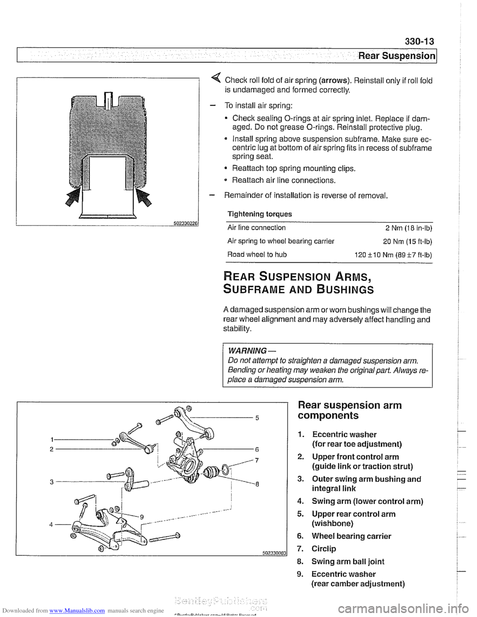
1 1 4 Check roll fold of air spring (arrows). Reinstall only if roll fold
is undamaged and formed correctly.
- To install air spring:
Check sealing O-rings at air spring inlet. Replace
if dam-
aged. Do not grease O-rings. Reinstall protective plug.
* Install spring above suspension subframe. Make sure ec-
centric lug at bottom of air spring fits in recess of
subframe
spring seat.
Reattach top spring mounting clips.
- Reattach air line connections.
- Remainder of installation is reverse of removal.
Tightening torques
Air line connection
2 Nm (1 8 in-lb)
Air spring
to wheel bearing carrier 20 Nm (1 5 ft-lb)
Road
wheel to hub 120 510 Nm (89-F-7 ft-lb)
REAR SUSPENSION ARMS,
SUBFRAME AND BUSHINGS
A damaged suspension arm orworn bushings will change the
rear wheel alignment and may adversely affect handling and
stability.
WARNING-
Do not attempt to straighten a damaged suspension arm.
Bending or heating may
weaken the original part. Always re-
olace a damaoed susoension arm.
Rear suspension arm
components
1. Eccentric washer
(for rear toe adjustment)
2. Upper front control arm
(guide link or traction strut)
3. Outer swing arm bushing and
integral link
4. Swing arm (lower control arm)
5. Upper rear control arm
(wishbone)
6. Wheel bearing carrier
7. Circlip
8. Swing arm ball joint
9. Eccentric washer
(rear camber adjustment)
Page 728 of 1002

Downloaded from www.Manualslib.com manuals search engine
I Rear Suspension
4 When installing subframe bushing, be sure alignment arrows
point front and rear.
Coat new mount with
CircolightB anti-friction agent.
< Draw new bushing into subframe using BMW special tools 33
4152,334153,334154,334155,334157.
- Remainder of installation is reverse of removal, noting the fol-
lowing.
* Tighten suspension arm and shock absorber fasteners to
final torque only after vehicle has been lowered and
sus-
oension has settled.
Rear wheel bearing carrier, removing and
installing (sedan models)
- Raise rear end of car and remove wheel
WARNING-
Make sure the car is firmly supported on jaclc stands de-
signed for the purpose. Place
jaclc stands underneath struc-
tural chassis points. Do not place jaclc stands under
suspension parts.
4 With an assistant applying brakes, break free and remove
staked collar nut (arrow).
- Remove brake caliper and brake disc. Hang brake caliper
aside with stiff wire. Do not disconnect brake fluid hose. See
340 Brakes.
- Disconnect parking brake cable from brake shoe expander.
See 340 Brakes.
Page 817 of 1002

Downloaded from www.Manualslib.com manuals search engine
Fenders, Ensine HOO~I
Hood release cable and spring pins,
adjusting
Before adjusting hood pins, be sure the hood is aligned even-
ly to fenders and front panel.
- Malte sure bowden cable, which connects both hood loclts
together, is seated in lock guide on both left and right loclts.
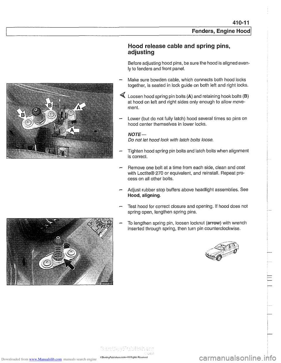
4 Loosen hood spring pin bolts (A) and retaining hoolt bolts (B)
at hood on left and right sides only enough to allow move-
ment.
- Lower (but do not fully latch) hood several times so pins on
hood center themselves in lower loclts.
NOTE-
Do not let hood lock with latch bolts loose
- Tighten hood spring pin bolts and latch bolts when alignment
is correct.
- Remove one bolt at a time from each side, clean and coat
with
LoctiteB 270 or equivalent, and reinstall. Repeat pro-
cess on all other bolts.
- Adjust rubber stop buffers above headlight assemblies. See
Hood, aligning.
- Test hood for correct closure and opening. If hood does not
spring open, lengthen spring pins.
- To lengthen spring pin, loosen locltnut (arrow) with wrench
inserted through spring, then turn pin counterclocltwise.
Page 852 of 1002

Downloaded from www.Manualslib.com manuals search engine
-
Exterior Trim, Bumpers
This repair group includes repair information for the outside
rearview mirrors, front and rear bumpers, and the easily re-
movable exterior trim parts.
Many of the mirror components are separately available from
an authorized
BMW dealer, including the glass and outside .
plastic housing.
The
E39 models offered two types of outside mirrors, stan-
dard mirrors or automatic dip mirrors.
Outside mirror glass, replacing
CAUTIOI\C
Mirrorshould be at or above room temperature before remov-
al.
Othe~lise, small plastic parfs or glass may break.
Outside mirror glass without automatic dip control,
replacing
Insert thin pry tool (plastic or tape-wrapped screwdriver) be-
tween bottom mirror edge and mirror housing and carefully
pry out mirror glass from housing.
If equipped with heated mirrors: remove heating element
har.
ness connectors from back of mirror glass.
Installation: Connect mirror heating harness if equipped.
Ensure correct alignment of locking pins.
Press mirror glass firmly until it
locks in place.
Page 933 of 1002

Downloaded from www.Manualslib.com manuals search engine
Sunroof, adjusting
The sunroof is controlled by a set of cables that move the sun-
roof panel along guide rails when the motor is operated. The
sunroof can be adjusted without removing it from the car.
NOTE-
Be sure to check drains in front corners of sunroof carrier if
water is entering car through headliner.
- The sunroof panel should be adjusted under the following cir-
cumstances:
Sunroof misaligned with roof.
Sunroof does not close squarely.
* Wind noise at high speeds (sunroof closed).
Sunroof has been removed.
For correct sunroof alignment:
Sunroof must be fully closed.
Gap must be even all around edge of sunroof.
Front of sunroof must be flush to
1 mm (0.04 in.) below sur-
face of roof.
. Rear of sunroof must be flush to 1 mm (0.04) above sur-
face of roof.
NOTE-
Use a credit card to measure the gap. The card sllould insert
through the gap with equal resistance all around the perimeter.
Sunroof with steel roof panel, adjusting
- The headliner panel must be disengaged from the drive as-
sembly and moved rearward in order to access the roof panel
attaching screws.
CAUTIOI\C
Sunroof panel must never be moved to open position when . .
I the headliner is disenaaaed. 1
- Start with a fully closed roof panel.
- Remove drive motor access cover. See Sunroof motor, re-
placing.
Using hex key from tool kit, turn motor drive 90" counter-
clockwise.
Rear of sunroof panel will drop
2 to 3 mm (0.08 to 0.12 in).
This disengages headliner from sunroof panel.
- Push headliner panel rearward, exposing roof panel attach-
ing screws.
Page 991 of 1002

Downloaded from www.Manualslib.com manuals search engine
INDEX 'tl
WARNING
Your common sense, good
judgemenl, and general alertness are
crucial to sale and successiul service
worlr. Belore attempting any work on
your
BMM be sure lo read 001
General Warnings and Cautions
and the
copyriglll page at the front 01
the manual. Review these warnings
and
caulions each lime you prepare
lo work on your BMW. Please also
read any warnings and cautions that
accompany
tile procedures in the
manual.
312-way valve (running losses)
see Fuel tank
Abbreviations, commonly used 600-14
ABS (antilock brake system)
see
Bral(es
A/C air distribution motors
see stepper motors (below)
blower final stage (resistor pack),
replacing
640-16
blower, removinglinslalling
640-1 5
compressor, replacing
640-24 condenser, replacing 64045
control panellmodule, removing1
installing
640-1 1
evaporakr, removinglinstalling 640-29
evaporator temperature sensor
640-12 expansion valve, removinglinstailing
640-27
IHKA/ IHKR system description 640-5
receiveridrier, replacing 640-26
stepper motors 640-1 3 ventilation microiilter, replacing
020-22. 640-17
see also Heating
Accelerator
iinlcage
see Maintenance
Activated carbon canister
see Fuel tank
ADS (auxiliary throttle valve)
130-57
Air compressor
330-44
Air conditioning
see
AIC
Air distribution (flap) motors
seeNC, stepper motors
Air filter see Maintenance
Air spring
300-6, 330-12
Airbag system (SRS)
2-stage
airbag 721-4
control module, replacing 721-7 driver airbag, removinglinstalling
721-8
iiead protection airbag 721-12 components 721-1 1
indicator
lighl721-4
passenger airbag, removinglinstalling
721-9 side-impact airbags crash sensor,
replacing
721-7
Airflow sensor see 130 under appropriate
fuel
injection system
Air pump
see 130 under appropriate fuel
injection system, secondary air
injection system
Air suspension
see Electronic height control
(EHC)
Alarm
see Anti-theft alarm
Alignment see
Wheei alignment
Aluminum suspension components
300-2
Antenna 650-6
Alternator see Battery, starter, alte rnator
Amplifier
650-4
Anti-theft alarm (DWA)
515-24 emergency disarming 515-31
Antifreeze (engine coolant)
see Maintenance
see also Cooling system
Antilock brake system (ABS) see Brakes
ASC see Brakes
ATF (automatic transmission fluid)
see Automatic transmission
see also Cooling systern
Automatic headlight adjustmenl
(LWR) see Lights
Automatic seat belt tensioner
720-4
Automatic shiftloclc
see
Gearshift
Automatic transmission
applications
200-3, 240-4
ATF 020-10, 200-4
capacity 240-8 checking 240-6
drainingifilling 240-7
heat exchanger 170-5
fluid pan and strainer 240-9 gearshift
see Gearshift
ID tag
200-3 range switch 610-6
removaliinstallation 240-10
steptronic see Gearshift
Auxiliary cooling fan
see
Coollng system, electric Ian
Auxiliary throttle valve (ADS)
130-57
Axle joint
see Drive axle
Back-up light switch
automatic transmission see Automatic transmission. range switch
- .~.~~~
manual transmission 230-8 -
- I
Page 1002 of 1002

Downloaded from www.Manualslib.com manuals search engine
112 INDEX
Warnings 001-1
Warnings, cautions and notes
01
0-3
Washer fluid pump
see Wipers and washers
Washers see Wipers and washers
Washing see Maintenance
Water pump
see Cooling system, coolant
pump
Waxing
see Mainienance
Wheel, steering
see Steering
Wheel alignment
320-33 ride [height 300-14
see also Maintenance
Wheel bearing
see Front suspension
see also Rear suspension
Wheels
300-1 1
Window motor see Door window
Window regulator
see Door window
Window switch
512-3
see Switches
Windows, door
see Door window
Windshield wipers and washers
see Wipers and washers
see also Maintenance
Wiper motor
see Wipers and washers Wipers and
washers
rain sensor 61
1-6 rear window (Sport Wagon) wiper motor, removingiinstaiiing
611-15 wiper shaft, removing.instaiiing
611-15
wiperiwasher system 61
1-8 washer system 611-16
wiper
assembly 611-12
wiper blades and arms 61 1-9
Wiring codes and abbreviations
600-12
Wirinq diaarams ELF-I -
see also Electrical system
Working under car safely
010-6
Xenon headlght
630-6
ZKE (central body electronics)
600-8