2001 BMW 530i vibration
[x] Cancel search: vibrationPage 20 of 1002

Downloaded from www.Manualslib.com manuals search engine
01 0-1 0
General
Electrical testing
Many electrical problems can be understood and solved with
only a little fundamental knowledge of how electrical circuits
function.
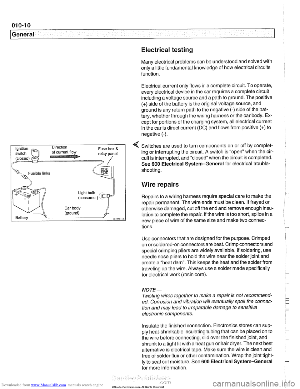
Electrical current
only flows in a complete circuit. To operate.
every electrical device in the car requires a complete circuit
including a voltage source and a path to ground. The positive
(+) side of the battery is the original voltage source, and
ground is any return path to the negative
(-) side of the bat-
tery, whether through the wiring harness or the car body. Ex-
cept for portions of the charging system, all electrical current
in the car is direct current (DC) and flows from positive
(+) to
negative
(-).
4 Switches are used to turn components on or off by complet-
ing or interrupting the circuit.
A switch is "open" when the cir-
cuit is interrupted, and "closed" when the circuit is completed.
See
600 Electrical System-General for electrical trouble-
(LW, 1 shooting
Wire repairs
Light bulb
(consumer) ' - Repairs to a wiring harness require special care to make the
repair permanent. The wire ends must be clean.
if frayed or
Car body otherwise damaged, cut off the end and remove enough insu- (ground) i Battery lation to complete the repair. if the wire is too short, splice in a BOZLiEL new piece of wire of the same size and make two connec-
tions.
Use connectors that are designed for the purpose. Crimped
on orsoldered-on connectors are best. Crimp connectors and
special crimping pliers are widely available. If soldering, use
needle nose pliers to hold the wire near the solder joint and
create a "heat dam". This keeps the heat and the solder from
traveling up the wire. Always use a solder made specifically
for electrical
work (rosin core).
NOJE-
Twisting wires together to make a repair is not recommend-
ed. Corrosion and vibration will eventually spoil the connec-
tion and may lead to irreparable damage to sensitive
electronic components.
Insulate the finished connection. Electronics stores can sup-
ply heat-shrinkable insulating tubing that can be placed on to
the wire before connecting, slid over the finished joint, and
shrunic to a tight fit with a heat gun or hair dryer. The next best
alternative is electrical tape. Make sure the wire is clean and
free of
solder flux or other contamination. Wrap the joint tight-
ly to seal out moisture. See
600 Electrical System-General
for more information.
Page 56 of 1002

Downloaded from www.Manualslib.com manuals search engine
020-24
Maintenance
tions. In general, replacement batteries should always be
rated equal or higher than the original battery.
The battery is held in place by a single hand screw and plate.
A secure battery hold-down is important in order to prevent
vibrations and road shoclt from damaging the battery.
CAUTION-
Prior to disconnecting the baitem read the battery discon-
nection cautions given in
001 General Cautions and
Warnings.
NOTE-
Always disconnect the negative (-) cable first, and connect
it last. While changing the battery, clean away any corro-
sion in or around the battery tray
More battery and charging system information is in 121
Battery, Alternator, Starter.
Brake fluid, replacing
Brake fluid absorbs moisture easily, and moisture in the fluid
affects bralte performance and reliability. This is why
BMW
strictly recommends replacing the bralte fluid every two
years. When replacing or adding bralte fluid, use only new
fluid from previously unopened containers. Do not use brake
fluid that has been bled from the system, even
if it is brand
new. Use only DOT
4 brake fluid.
NOTE-
See 340 Brakes for brake fluid flushing procedures.
Brake pad 1 rotor wear, checking
Disc brakes are fitted at all four wheels. Although the brakes
are equipped with a brake pad warning system, the system
only monitors one wheel per axle. Pad thickness should be
checked whenever wheels are off or brake
worlt is being
done.
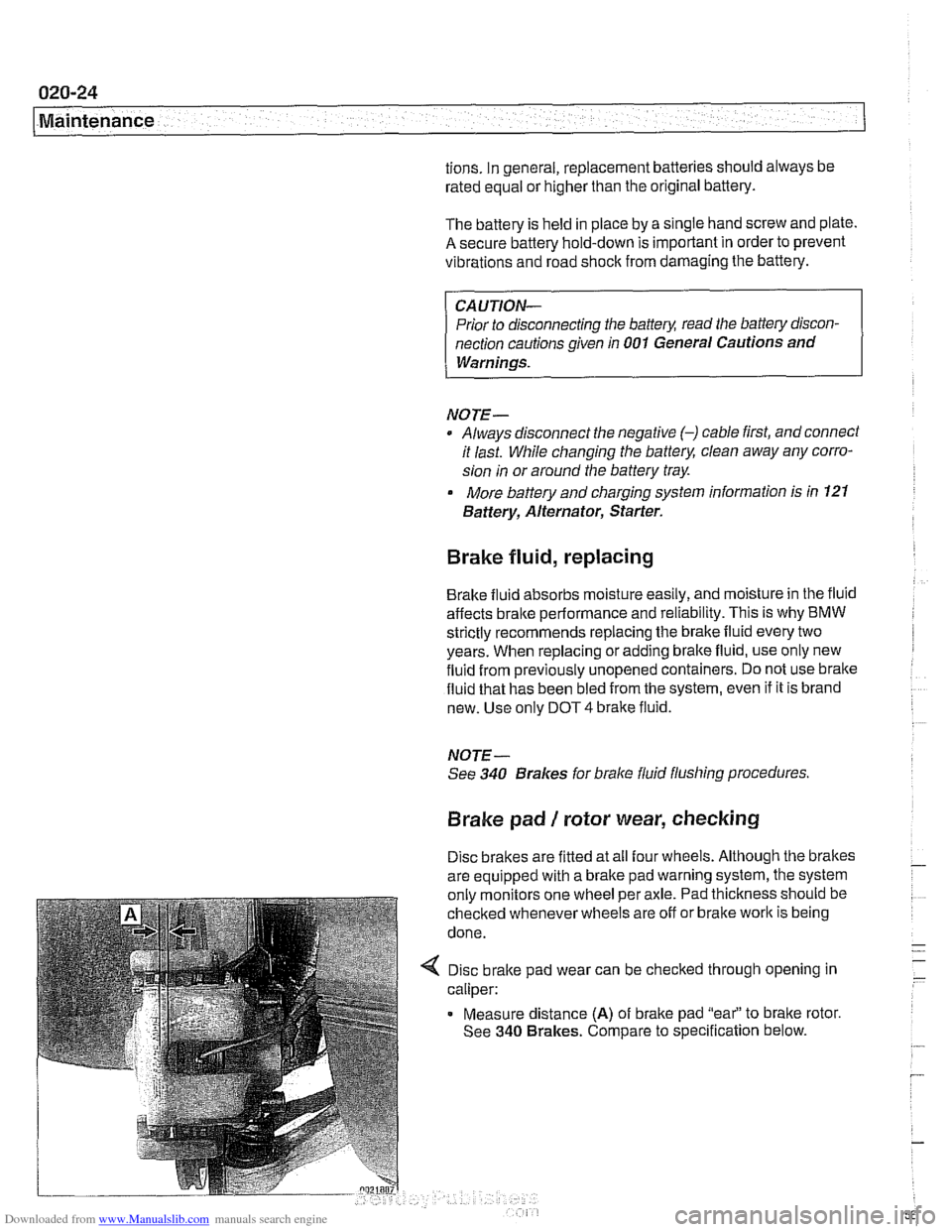
4 Disc brake pad wear can be checked through opening in
caliper:
Measure distance
(A) of brake pad "eai' to bralte rotor.
See
340 Brakes. Compare to specification below.
Page 71 of 1002

Downloaded from www.Manualslib.com manuals search engine
Two common causes of driveability problems are incorrect
system voltage and bad grounds.
System voltage
Digital motor electronics (DME) requires that the system (bat-
tery) voltage be maintained within a narrow range of DC volt-
age.
DC voltage levels beyond or below the operating range,
or any
AIC voltage in the electrical system can cause havoc.
When troubleshooting an illuminated MIL, make sure the bat-
tery is fully charged and capable of delivering all its power to
the electrical system. An undercharged battery can amplify
AIC alternator output ripple.
To
make a quick check of the battery charge, measure the
voltage across the battery terminals with all cables attached
and the ignition off.
Afully charged battery will measure 12.6
volts or slightly more, compared to 12.1 5 volts for a battery
with a 25% charge.
The DME system operates at low voltage and current levels,
making it sensitive to small increases in resistance. The elec-
trical system is routinely subjected to corrosion, vibration and
wear, so faults or corrosion in the wiring harness and connec-
tors are not uncommon. Check the battery terminals
forcorro-
sion or loose cable connections. See 121 Battery, Starter,
Alternator for additional information.
If a battery cable connection has no
v~sible faults but is still
suspect, measure the voltage drop across the connection. A
large drop indicates excessive resistance, meaning that the
connection is corroded, dirty, or damaged. Clean or repairthe
connection and retest.
NOTE-
For instructions on conducting a voltage drop test and other
general electrical troubleshooting information, see
600 Elec-
trical System-General.
Visually inspect all wiring, connectors, switches and fuses in
the system. Loose or damaged connectors can cause inter-
mittent problems, especially the small terminals in the ECM
connectors. Disconnect the wiring harness connectors to
check for corrosion, and use electrical cleaning spray to re-
move contaminants.
Main grounds
Good grounds are critical to proper DME operation. If a
ground connection has no visible faults but is still suspect.
measure the voltage drop across the connection. A large volt-
age drop means high resistance. Clean or repair the connec-
tion and retest.
LBuntr.yP~sbhnllcn.can#-AII A,~iltl Rcsrwsd
Page 107 of 1002

Downloaded from www.Manualslib.com manuals search engine
- - , -. I Cylinder Head Removal and lnstallatio~
4 Remove oil baffle cover from above intake camshaft.
4 Unscrew and remove three cylinder head cover studs (ar-
rows)
at rear of cylinder head.
Set engine to approximate top dead center
(TDC) by turning
crankshaft bolt in direction of rotation (clocltwise when
viewed from front of engine) until camshaft lobes for cylinder
1 face each other (dotted lines) and arrows on camshaft
sprocltets face up.
- Set engine to TDC by aligning "OIP mark of vibration damp-
er with boss cast on lower timing chain cover.
< Lock cranltshaft at TDC:
Remove sealing plug from bore on lower left side of engine
block below starter. Secure crankshaft in
TDC position with
BMW special tool 11 2 300.
Page 110 of 1002

Downloaded from www.Manualslib.com manuals search engine
113-16
Cylinder Head Removal and Installation
- Remove secondary timing chain and sprockets:
Remove mounting nuts from front of intake camshaft
sprocket. Remove and label shim.
CAUTION-
Hold the camshaft stationary (at hex on camshaft) when loos-
ening or tightening sprocket mounting fasteners.
Remove mounting nuts from front of exhaust camshaft
sprocket and remove and label thrust washer.
NOTE-
Where applicable, make note of thrust washerpositions. The
thicker
(0.4 mm) washer is mounted outermost.
- Remove secondary sprockets together with camshaft tim-
ing chain from front of camshafts.
CAUTION-
The camshafts must be locledin the TDCposition using the
special service tool as described earlier: The arrows on the
sprockets should not be used to accurately set the engine to
TDC. The tool holds the camshafts parallel to each other and
NOTE-
Do not remove the sprocl
to
Iceep the sproclefs timed to each other:
CAUTIOI\C
The crankshaft must not be allowed to rotate once the cam-
shaft timing chain is removed. The pistons can
contact the
valves.
Unscrew timing chain guide and remove.
Lift off primary sprocket with chain.
Secure chain with wire to prevent chain from dropping into
lower timing cover.
Unscrew timing case cover to cylinder head bolts (arrows).
NOTE-
Photo shows timing chain guide in place; it should first be re-
moved as described previously.
Remove crankshaft locking tool
(BMW special tool 11 2 300).
Using the crankshaft vibration damper bolt, turn engine op-
posite of normal direction of rotation (counterclocltwise as
viewed from the front) approximately 30". This prevents ac-
cidental contact between valves and pistons during installa-
tion.
Page 131 of 1002

Downloaded from www.Manualslib.com manuals search engine
Cylinder Head Removal and Installation I
Remove cylinder head cover mounting studs (arrows) from
center of cylinder head.
- Remove crankshaft loclting tool from transmission bell hous-
Ing.
Lift primary chain and hold under tension, then rotate engine
at vibration damper in opposite direction of normal rotation
(counterclocltwise) approximately 30".
CAUTION-
By turning crankshait3O0, pistons are movedaway from top
dead center, to prevent possible valve interference to pistons
during camshaft servicing.
- Remove camshaft loclting tools (BMW special tool set 11 3
240) from rear of cylinder head.
4 Remove camshaft bearing cap 1 on intake camshaft.
4 Fit BMW special tools 11 3 260 (A) and 11 3 270 (B) to cyl-
inder head and screw long bolts (arrows) into spark plug
threads. Tensioning pins on tool will align with the bearing
caps on the
intake camshaft.
CAUJION-
Do not over torque bolts into sparkplug holes.
Page 139 of 1002

Downloaded from www.Manualslib.com manuals search engine
Cylinder Head Removal and Installation
4 While maintaining tension on timing chain, rotate crankshaft
at vibration damper from
30" before TDC in direction of rota-
tion (clockwise) until number
1 cylinder is at TDC position
with line between the
OIT (arrow) on front pulley lined up
with boss on lower timing chain cover.
Page 157 of 1002

Downloaded from www.Manualslib.com manuals search engine
.- --
Cylinder Head Removal and Installation I
4 Rotate crankshaft vibration damper to TDC position. Right
head camshaft lobes for number one cylinder should be in
position shown (arrows).
Working at right cylinder head (passengers side) loosen re-
maining
sprocltet fasteners (arrows) on both intake and ex-
haust camshafts approximately
'/? turn.
4 Loosen and remove primary timing chain tensioner (arrow)
from upper timing chain cover on right head.