2001 BMW 525i Throttle
[x] Cancel search: ThrottlePage 87 of 1002

Downloaded from www.Manualslib.com manuals search engine
110-15
Engine Removal and lnstallation
- Installation is reverse of removal, noting the following:
Replace all gaskets. O-rings and seals.
Use new fuel injector seals
Check that engine drive belts properly engage pulley
grooves.
Inspect O-ring seal between mass air flow sensor and air
filter housing. To facilitate reassembly, coat seal with acid-
free grease.
Change engine oil and filter and
check all other fluid levels.
See
020 Maintenance.
Refill and bleed cooling system. See
170 Radiator and
Cooling System.
CAUTION--
When reattaching throttle assembly harness connectoc con-
nector is
fuNy tightened when arrows on connector and plug
line up.
Tightening torques
Coolant drain plug to cylinder block
25 Nm (18 ft-lb)
Engine mount to
subframe (M10) 45 Nm (33 ft-ib)
Exhaust manifold to cylinder head
M6 10 Nm (89 in-lb)
M7 or ME 20 Nm (15 ft-lb)
Intake manifold to cylinder head
M7 15 Nm (I 1 ft-lb)
ME 22 Nm (16 ft-lb)
Radiator cooling fan to coolant pump
40 Nm (30 ft-lb)
Radiator drain screw to radiator
2.5 Nm (22 in-lb)
Page 90 of 1002

Downloaded from www.Manualslib.com manuals search engine
I Engine Removal and Installation
WARNING -
Use extreme caution when draining and disposing of engine
coolant. Coolant is poisonous andlethal to humans andpets.
Pets are attracted to coolant because of its sweet smell and
taste. Seek medical attention immediately if coolant is ingest-
---
Working at rear of intake manifold:
Disconnect brake booster vacuum line (A).
Disconnect fuel tank vent line
(6).
Disconnect hoses (C and D) at coolant manifold
- Remove transmission harness support (E).
- Remove oil filter housing assembly from fender:
- Remove oil filter housing mounting fasteners.
Use stiff wire to secure oil filter housing to engine.
NOTE-
Do not disconnect oil lines from filter housing.
4 Disconnect supply and return fuel lines (where applicable) at
or near fuel rail. Plug open fuel lines.
NOTE-
BMW uses three styles of fuel line connections; a slngle use
clamp, a locking fitting that uses special tool
16 7 050 to re-
lease, and a
quiclc release sleeve (arrows) that disconnects
the line when depressed.
WARNING-
Fuel In fuel line is under pressure (approx. 3 - 5 bar or45 -
75 psi) and may be expelled. Do not smoke or worlc near
heaters or other fire hazards. Keep a fire extinguisher
handy. Before disconnecting fuel hoses, wrap a cloth
around fuel hoses to absorb any lealcing fuel. Catch and
dispose of escaped fuel. Plug all open fuel lines.
. Always unscrew the fuel tank cap to release pressure
in the tank before worlcing on the tank or lines.
< Remove air filter housing and mass air flow sensor:
Disconnect mass air flow sensor (A) and
intalte air temper-
ature sensor
(6) electrical harness connectors.
. Remove air filter housing mounting fastener (arrow).
Loosen intake hose clamp (C).
M62 engine: Remove hose at idle air stabilizer.
Remove air filter housing with mass air flow sensor.
Remove intalte hose from throttle body.
Page 91 of 1002

Downloaded from www.Manualslib.com manuals search engine
110-19
Engine Removal and Installation
M62 engine, remove ASC throttle body.
Disconnect electrical harness from throttle position sensor.
- Disconnect ASC actuator cable (arrow).
. Remove mounting fasteners and remove throttle body.
On front of left side cylinder head, disconnect electrical har-
ness connector
(A), and remove and plug fuel tank vent valve
vacuum line
(0).
Raise car and support in a safe manner.
CAUTION-
Male sure the car is stable and well supported at aN times.
Use a professional automotive
lifi orjackstands designed for
I the ouroose. A floor jack is not adequate support.
Working beneath car:
- Remove engine splash shield.
Remove right and left heat shield from front suspension
subframe.
Working underneath engine compartment, disconnect
ground cable on right side engine mount
(arrow).
Page 103 of 1002

Downloaded from www.Manualslib.com manuals search engine
11 3-9
Cylinder Head Removal and Installation
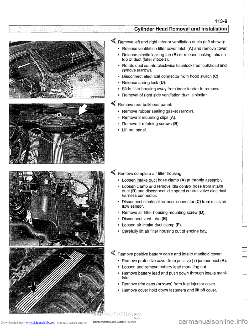
< Remove left and right interior ventilation ducts (left shown):
Release ventilation filter cover latch (A) and remove cover.
Release plastic locking tab
(6) or release locking tabs on
top of duct (later models).
Rotate duct counterclockwise to unlock from bulkhead and
remove (arrow).
Disconnect electrical connector from hood switch
(C).
Release spring lock (D).
Slide filter housing away from inner fender to remove.
Removal of right side ventilation duct is similar.
Remove rear bulkhead panel: Remove rubber sealing
gasket (arrow).
0 Remove 3 mounting clips (A).
Remove
4 retaining screws (6).
Lift out panel.
< Remove complete air filter housing:
Loosen
intake duct hose clamp (A) at throttle assembly.
Loosen clamp and remove idle control hose from
~ntake
duct (6) and disconnect Idle speed control valve electr~cal
harness connector.
Disconnect
electr~cal harness connector (C) from mass alr
flow sensor.
Remove air filter housing mounting screw (D).
Disconnect vent tube
(E).
Loosen air intake duct clamp (F).
Carefully lift air filter housing out of engine bay.
4 Remove positive battery cable and intake manifold cover:
Remove protective cover from positive (+)jumper post (A).
Loosen and remove battery lead mounting nut.
Remove battery lead and push down through intake mani-
fold.
Remove trim caps (arrows) from fuel injector cover.
Remove cover hold down fasteners and lift off cover.
Page 104 of 1002

Downloaded from www.Manualslib.com manuals search engine
113-10
Cylinder Head Removal and Installation
4 Working above engine, disconnect the following:
Vent line from cylinder head cover
(A).
. Oxygen sensor connectors (B).
Electrical harness connector from VANOS solenoid
valve
(C).
Electrical harness connectors at throttle valve position
switch
(D), ASC valve position switch (E), fuel injector har-
ness
(F) and vent valve (G).
CAUTION-
Be sure to mark oxygen sensor harness connectors so that
they can be reassembled correctly Do not interchange con-
nectors.
4 Where applicable, remove schraeder valve cap (arrow) from
air connection on fuel rail. Using a tire chuck, blow fuel back
through feed line using a brief burst of compressed air (max-
imum of
3 bar or 43.5 psi).
WARNING-
. Fuel in fuel line is underpressure (approx. 3 - 5 bar or 45 -
75 psi) and may be expelled. Do not smoke or work near
heaters or other fire hazards. Keep a fire extinguisher
handy Before disconnecting fuel hoses, wrap a cloth
around fuel hoses to absorb any leaking fuel. Catch and
dispose of escaped fuel. Plug open fuel lines.
- Always unscrew the fuel rank cap ro release pressure
;n the tank before working on the tank or lines.
Disconnect fuel lines by sliding locking collar in (arrows) and
pulling lines apart.
NOTE-
BMW uses three styles of fuel line connections; a one-time
use
clamp; a locking fitting that uses BMWspecial tool 16 1
050 to release; and a quick release sleeve (above) that dis-
connects the line when depressed.
Page 105 of 1002

Downloaded from www.Manualslib.com manuals search engine
..
Cylinder Head Removal and Installation 1
< Remove intake throttle valve and ASC throttle assemblies:
Disconnect ASC throttle cable
(A).
- Remove ASC throttle housing mounting fasteners (B).
NOTE-
It is not necessary to disconnect coolant hoses (C) 01
bowden cables (D).
Remove intake throttle housing mounting hardware, pull
throttle housing off
intake manifold, and set aside.
- Working under intake manifold, disconnect the following:
Engine oil dipstick tube support.
Oil separator return line from dipstick tube.
Intake air temperature sensor electrical harness connector
(underside of intake manifold near throttle body).
* Fuel tank vent line and electrical harness at canister vent
valve.
Remove lower intake manifold supports (arrows).
- Disconnect coolant line retaining bracket at cylinder block.
4 Remove manifold mounting hardware (arrows).
- Remove intake manifold from cylinder head while carefully
checking for electrical connections or hoses.
NOTE-
Fuel rail is removed with intake manifold,
CAUTIOI\C
Stuff clean rags into open intake ports to prevent any parts
from falling into
Nie engine intake.
- Drain cooling system (engine block and radiator), then re-
move radiator cooling fan and fan shroud. See
170 Radiator
and Cooling System.
- Disconnect coolant hoses from thermostat housing.
Page 117 of 1002

Downloaded from www.Manualslib.com manuals search engine
- --
Cylinder Head Removal and Installation 1 --
< Remove complete air filter housing assembly with mass air
flow sensor:
Loosen
intalte duct hose clamp (A) at throttle assembly.
Loosen clamp and remove idle control line from intake duct
(B) and disconnect idle speed control valve electrical har-
ness connector.
Disconnect electrical harness connector
(C) from mass air
flow sensor.
Remove air filter housing mounting screw
(D).
Disconnect vent tube (E).
. Loosen air intalte duct clamp (F).
Carefully lifl air filter housing, mass air flow sensor, and in-
take duct hose out of engine bay.
4 Disconnect positive battery cable and remove intake rnani-
fold cover:
Remove protective cover from positive (+)jumper post.
Loosen and remove battery lead mounting nut (A).
Remove lead and push down through intake manifold.
* Remove trim covers (arrows) from fuel injector cover.
Remove cover hold down fasteners and lifl off cover.
4 Worlting above engine, disconnect the following:
Vent line from cylinder head cover. To remove, pinch clips
(arrows).
Electrical harness connector from VANOS solenoid valve
(A).
- Remove oxygen sensors and exhaust manifolds. See 180
Exhaust System.
CAUTION-
Remove oxygen sensors before removing exhaust mani-
fold to prevent damage.
Label oxygen sensor harness connectors so that they
can be reassembled correctly Do not interchange con-
nectors.
NOTE-
Front exhaust manifold must be removed before rear
manifold.
Page 119 of 1002

Downloaded from www.Manualslib.com manuals search engine
11 3-25
Cylinder Head Removal and Installation
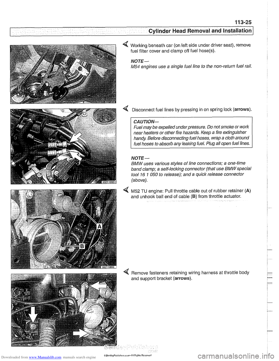
4 Working beneath car (on left side under driver seat), remove
fuel filter cover and clamp
off fuel hose(s).
NOTE-
M54 engines use a single fuel line to the non-return fuel rail.
Disconnect fuel lines by pressing in on spring lock (arrows).
CAUTION--
Fuel may be expelled underpressure. Do not smoke or worlc
near heaters or other fire hazards. Keep a fire extinguisher
handy Before disconnecting fuel hoses, wrap a cloth around
fuel hoses to absorb any leaking fuel. Plug all open fuel lines.
NOJE-
BMW uses various styles of line connections; a one-time
band clamp; a
self-locl(ing connector (that use BMWspecial
tool 16 1 050 to release); and a quick release connector
(above).
4 M52 TU engine: Pull throttle cable out of rubber retainer (A)
and unhook ball end of cable (6) from throttle actuator.
4 Remove fasteners retaining wiring harness at throttle body
and support bracket (arrows).