2001 BMW 525i Tail light
[x] Cancel search: Tail lightPage 31 of 1002

Downloaded from www.Manualslib.com manuals search engine
Spare parts kit
Carrying a basic set of spare parts can prevent a rninorbreak-
down from turning into a major repair annoyance. The list be-
low is a good place to start.
Spare parts kit
- basic
Polyribbed drive
belt(s)
BMW engine oil: one or two quarts
BMW engine coolant:
1 gallon of premixed 50150 BMW
anti-freeze and water
Fuse assortment:
7.5A. IOA, 1 5A, 20A, 30A. 50A
Radiator hoses: upper and lower
Spare parts
kit - additional contents
Exterior lighting bulbs: headlight, bralte light, turn signal,
and taillight
* Wiper blades or blade inserts
Brake fluid: new, unopened bottle, DOT
4 specification
Main relay for DME system
Page 51 of 1002

Downloaded from www.Manualslib.com manuals search engine
Maintenance
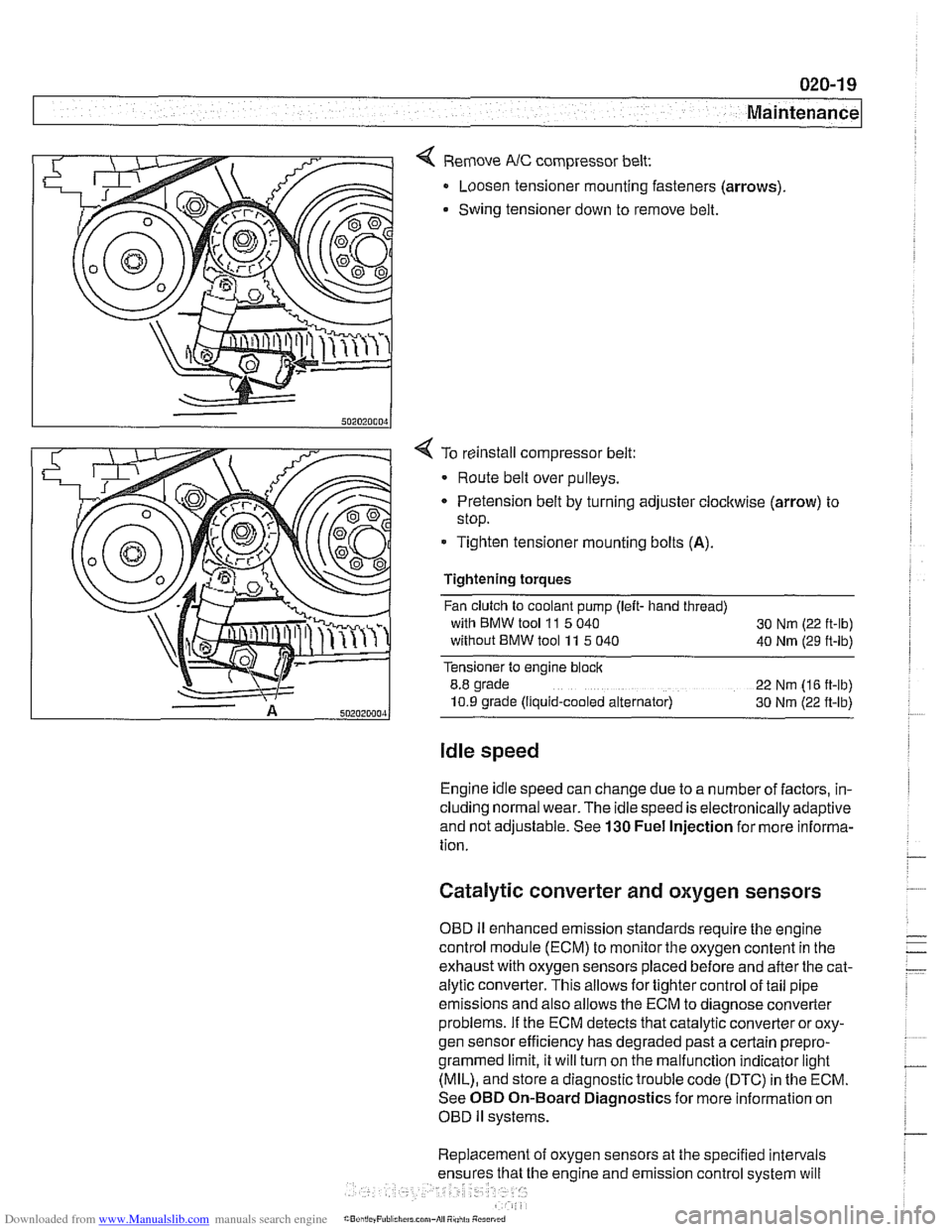
< Remove NC compressor belt:
Loosen tensioner mounting fasteners (arrows)
Swing tensioner down to remove belt.
4 To reinstall compressor belt:
Route belt over pulleys.
* Pretension belt by turning adjuster clockwise (arrow) to
stop.
- Tighten tensioner mounting bolts (A).
Tightening torques
Fan clutch to coolant pump (left- hand thread)
with BMW tool
11 5 040
30 Nm (22 ft-lb)
without BMW tool 11 5 040
40 Nm (29 ft-lb)
Tensioner to engine block
8.8 grade
22 Nm (16 ft-lb)
10.9 grade (Ilquid-cooled alternator) 30 Nm (22 ft-lb)
Idle speed
Engine idle speed can change due to a number of factors, in-
cluding normal wear. The idle speed is electronically adaptive
and not adjustable. See
130 Fuel Injection for more informa-
tion.
Catalytic converter and oxygen sensors
OBD II enhanced emission standards require the engine
control module (ECM) to monitor the oxygen content in the
exhaust with oxygen sensors placed before and after the cat-
alytic converter. This allows for tighter control of tail pipe
emissions and also allows the ECM to diagnose converter
problems. If the ECM detects that catalytic converter or oxy-
gen sensor efficiency has degraded past a certain
prepro-
grammed limit, it will turn on the malfunction indicator light
(MIL), and store a diagnostic trouble code (DTC) in the ECM.
See OBD On-Board Diagnostics for more information on
OBD
ll systems.
Replacement of oxygen sensors at the specified intervals
he engine and emission control system will
Page 72 of 1002

Downloaded from www.Manualslib.com manuals search engine
100-6
( Engine-General
The main grounds for the fuel and ignition circuits of the DME
system are illustrated below; see 610 Electrical Component
Locations for additional ground and component locations.
4 Ground for engine management system in right rear of en-
gine compartment on E-box bulkhead (arrow).
6-cylinder models: Grounds
for ignition coils (arrows)
4 V-8 models: Grounds for ignition coils, at cylinders 3
(arrow) and 7.
4 Fuel pump ground (arrow) below right tail light in luggage
compartment.
NOTE-
Ground location for sedan shown, wagon models may
differ.
Page 831 of 1002

Downloaded from www.Manualslib.com manuals search engine
Trunk Lid, Tailgate
4 Pry out trunk light and disconnect electrical harness plug
connector.
- Gently pry trunk liner away from lid and remove.
4 Disconnect Wiring connectors A, B and C. Remove wiring
harness by pulling through opening in lid frame
D.
While supporting trunk lid, loosen left and right top hinge fas-
teners (arrow
A) and remove lower fasteners (arrow B).
NOTE-
Before loosening hinge bolts, mark hinge and hinge bolt lo-
cations for
reins~alla~on
Lift trunk lid straight up to remove.
Installation is reverse of removal. If necessary, align trunk lid
to body as described in
Trunk lid, adjusting.
Page 901 of 1002

Downloaded from www.Manualslib.com manuals search engine
Central Locking and Anti-Theft
Trunk lock
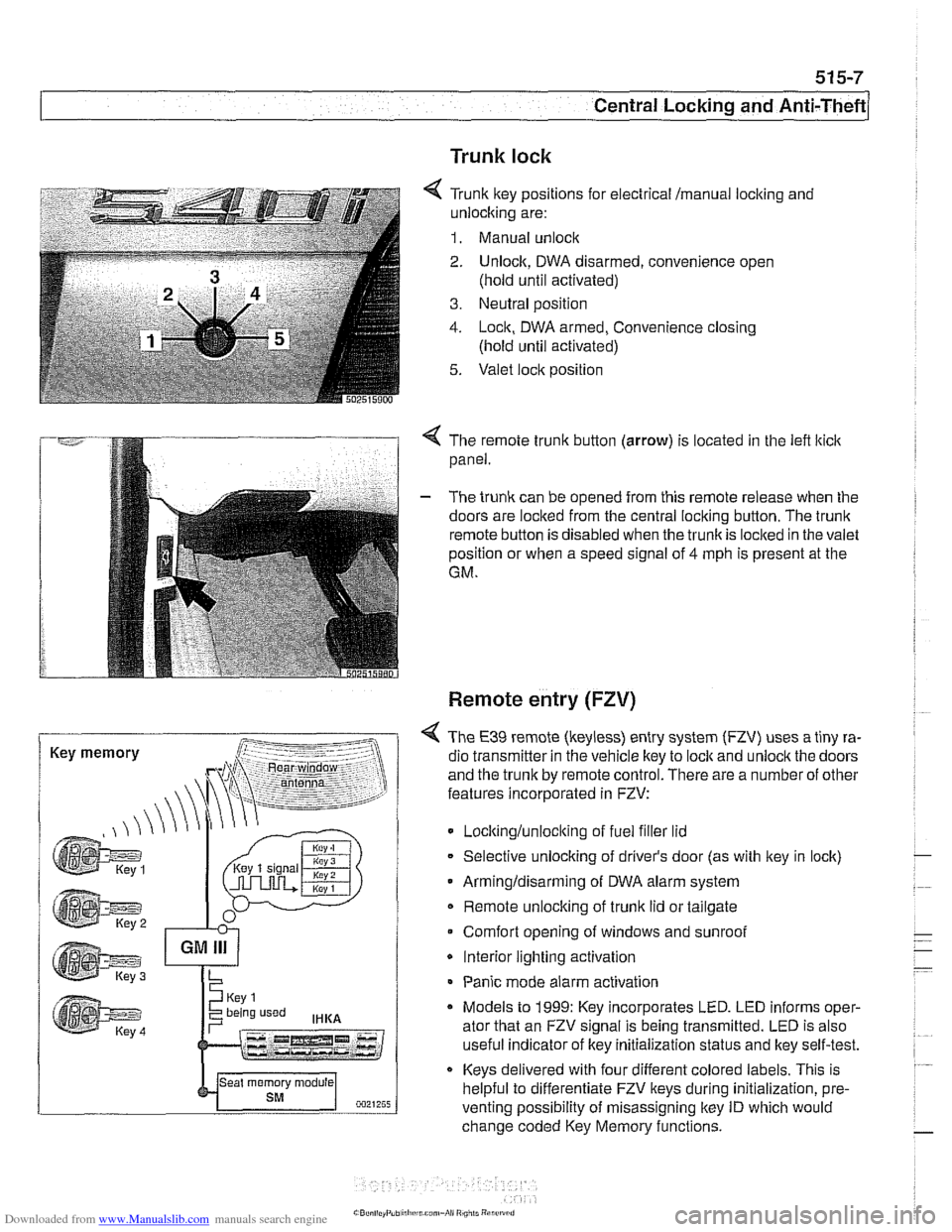
6 Tr~nk ftey pos~rions for eecir'cal mama, locking and
-nlock~ng are:
1. Manual unock .. - - - ........ - ..- .- ................. s.=.=-- 2. Unlock. DWA oisarmed, conven:ence open
(nold
un1:l aclivaledj
3. Ne~tral posit'on
1. -ocn. DWA armeo, Convenience closng
(hold ~nti activated)
5. Valet .oc,t position
. -- .............-... .- . - -.....
Key memory
< The remote trunk button (arrow) is located in the lefl lticlc
panel.
- The trunk can be opened from this remote release when the
doors are locked from the central locking button. The
trunk
remote button is disabled when the trunkis loclted in the valet
position or when a speed signal of
4 mph is present at the
GM.
Remote entry (FZV)
< The €39 remote (keyless) entry system (FZV) uses a tiny ra-
dio transmitter in the vehicle key to
lock and unlock the doors
and the trunk by remote control. There are a number of other
features incorporated in FZV:
Locltinglunloclting of fuel filler lid
Selective unlocking of driver's door (as with key in lock)
Armingldisarming of DWA alarm system
Remote unlocking of
trunk lid or tailgate
Comfort opening of windows and sunroof
* Interior lighting activation
Panic mode alarm activation
* Models to 1999: Key incorporates LED. LED informs oper-
ator that an FZV signal is being transmitted. LED is also
useful indicator of key initialization status and lkey self-test.
Keys delivered with four different colored labels. This is
helpful to differentiate FZV keys during initialization,
pre.
venting possibility of misassigning key ID which would
change coded Key Memory functions.
Page 909 of 1002

Downloaded from www.Manualslib.com manuals search engine
51 5-1 5
Central Locking and Anti-Theft
Any of these input requests to the GM activates the tailgate
latch motor. The
GM will also switch on the interior lights with
a tailgate unlock request.
The rearwindow is opened with the release switch on the rear
wiper arm cover. Pressing the switch signals the GM to acti-
vate the rear window release relay.
Sport Wagon tailgate and rear window lock
schematic
Inputs Outputs
"UiRWiNOOW ACTUATOR RELAY
RUiRWINDOW ACTUlimR A L
WIPERS
Page 918 of 1002

Downloaded from www.Manualslib.com manuals search engine
51 5-24
l~entral Locking and Anti-Theft
ANTI-THEFT SYSTEM (DWA)
When the anti-then system (DWA) is armed, the doors, hood,
windows, trunk lid or tailgate are monitored against forcible
entry by switches and sensors. The vehicle is protected
against being jacked up or towed away by a tilt sensor.
The control electronics for DWA are integrated in the General
Module (GM). In addition to the control electronics, the sys-
tem includes the following components.
* DWA horn
DWA LED indicator
- Tilt sensor
- Monitoring switches and sensors
The system can be armed or disarmed from the driver's door
lock,
trunklid lock, tailgate lockorthe remote transmitter (FZV
Itey). When armed, the alarm horn
soundsfor30seconds and
the low beam headlights and turn signals flash for
5 minutes.
The electronic immobilizer (EWS) is also activated when
DWA is activated.
The alarm is switched off immediately if key is inserted in door
loclt or FZV key button is used.
DWA LED Status
The DWA status LED is located in the rear view mirror (ar-
row). When DWA is armed, the LED flashes slowly to indi-
cate armed status.
The LED and exterior lights flash once and the alarm horn
sounds when the system is successfully armed ordisarmed.
The LED will continue to flash slowly denoting the armed sta-
tus. If any monitored input is not closed when the system is
armed, the LED will flash rapidly for
10 seconds to indicate
the fault.
Tilt sensor
-
4 The tilt sensor, located on the left side of trunlt or cargo com- -
partment, consists of a conductive liquid chamber, a proces-
sor board and metal probes. The probes are submersed in
the liquid and produce a resistance value dependent on the
tilt of the sensor (angle of the vehicle). This resistance be-
comes the reference value when the DWA system is armed.
.-
Page 991 of 1002

Downloaded from www.Manualslib.com manuals search engine
INDEX 'tl
WARNING
Your common sense, good
judgemenl, and general alertness are
crucial to sale and successiul service
worlr. Belore attempting any work on
your
BMM be sure lo read 001
General Warnings and Cautions
and the
copyriglll page at the front 01
the manual. Review these warnings
and
caulions each lime you prepare
lo work on your BMW. Please also
read any warnings and cautions that
accompany
tile procedures in the
manual.
312-way valve (running losses)
see Fuel tank
Abbreviations, commonly used 600-14
ABS (antilock brake system)
see
Bral(es
A/C air distribution motors
see stepper motors (below)
blower final stage (resistor pack),
replacing
640-16
blower, removinglinslalling
640-1 5
compressor, replacing
640-24 condenser, replacing 64045
control panellmodule, removing1
installing
640-1 1
evaporakr, removinglinstalling 640-29
evaporator temperature sensor
640-12 expansion valve, removinglinstailing
640-27
IHKA/ IHKR system description 640-5
receiveridrier, replacing 640-26
stepper motors 640-1 3 ventilation microiilter, replacing
020-22. 640-17
see also Heating
Accelerator
iinlcage
see Maintenance
Activated carbon canister
see Fuel tank
ADS (auxiliary throttle valve)
130-57
Air compressor
330-44
Air conditioning
see
AIC
Air distribution (flap) motors
seeNC, stepper motors
Air filter see Maintenance
Air spring
300-6, 330-12
Airbag system (SRS)
2-stage
airbag 721-4
control module, replacing 721-7 driver airbag, removinglinstalling
721-8
iiead protection airbag 721-12 components 721-1 1
indicator
lighl721-4
passenger airbag, removinglinstalling
721-9 side-impact airbags crash sensor,
replacing
721-7
Airflow sensor see 130 under appropriate
fuel
injection system
Air pump
see 130 under appropriate fuel
injection system, secondary air
injection system
Air suspension
see Electronic height control
(EHC)
Alarm
see Anti-theft alarm
Alignment see
Wheei alignment
Aluminum suspension components
300-2
Antenna 650-6
Alternator see Battery, starter, alte rnator
Amplifier
650-4
Anti-theft alarm (DWA)
515-24 emergency disarming 515-31
Antifreeze (engine coolant)
see Maintenance
see also Cooling system
Antilock brake system (ABS) see Brakes
ASC see Brakes
ATF (automatic transmission fluid)
see Automatic transmission
see also Cooling systern
Automatic headlight adjustmenl
(LWR) see Lights
Automatic seat belt tensioner
720-4
Automatic shiftloclc
see
Gearshift
Automatic transmission
applications
200-3, 240-4
ATF 020-10, 200-4
capacity 240-8 checking 240-6
drainingifilling 240-7
heat exchanger 170-5
fluid pan and strainer 240-9 gearshift
see Gearshift
ID tag
200-3 range switch 610-6
removaliinstallation 240-10
steptronic see Gearshift
Auxiliary cooling fan
see
Coollng system, electric Ian
Auxiliary throttle valve (ADS)
130-57
Axle joint
see Drive axle
Back-up light switch
automatic transmission see Automatic transmission. range switch
- .~.~~~
manual transmission 230-8 -
- I