Page 59 of 88
Downloaded from www.Manualslib.com manuals search engine
59
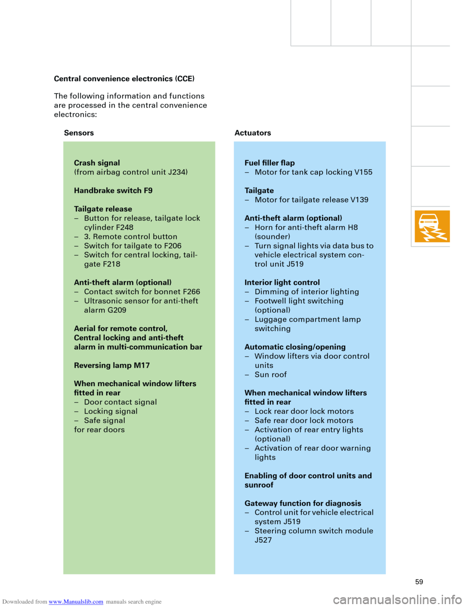
The following information and functions
are processed in the central convenience
electronics:
Crash signal
(from airbag control unit J234)
Handbrake switch F9
Tailgate release
– Button for release, tailgate lock
cylinder F248
– 3. Remote control button
– Switch for tailgate to F206
– Switch for central locking, tail-
gate F218
Anti-theft alarm (optional)
– Contact switch for bonnet F266
– Ultrasonic sensor for anti-theft
alarm G209
Aerial for remote control,
Central locking and anti-theft
alarm in multi-communication bar
Reversing lamp M17
When mechanical window lifters
fitted in rear
– Door contact signal
– Locking signal
– Safe signal
for rear doors
Fuel filler flap
– Motor for tank cap locking V155
Tailgate
– Motor for tailgate release V139
Anti-theft alarm (optional)
– Horn for anti-theft alarm H8
(sounder)
– Turn signal lights via data bus to
vehicle electrical system con-
trol unit J519
Interior light control
– Dimming of interior lighting
– Footwell light switching
(optional)
– Luggage compartment lamp
switching
Automatic closing/opening
– Window lifters via door control
units
– Sun roof
When mechanical window lifters
fitted in rear
– Lock rear door lock motors
– Safe rear door lock motors
– Activation of rear entry lights
(optional)
– Activation of rear door warning
lights
Enabling of door control units and
sunroof
Gateway function for diagnosis
– Control unit for vehicle electrical
system J519
– Steering column switch module
J527
Sensors Actuators Central convenience electronics (CCE)
Page 60 of 88
Downloaded from www.Manualslib.com manuals search engine
60
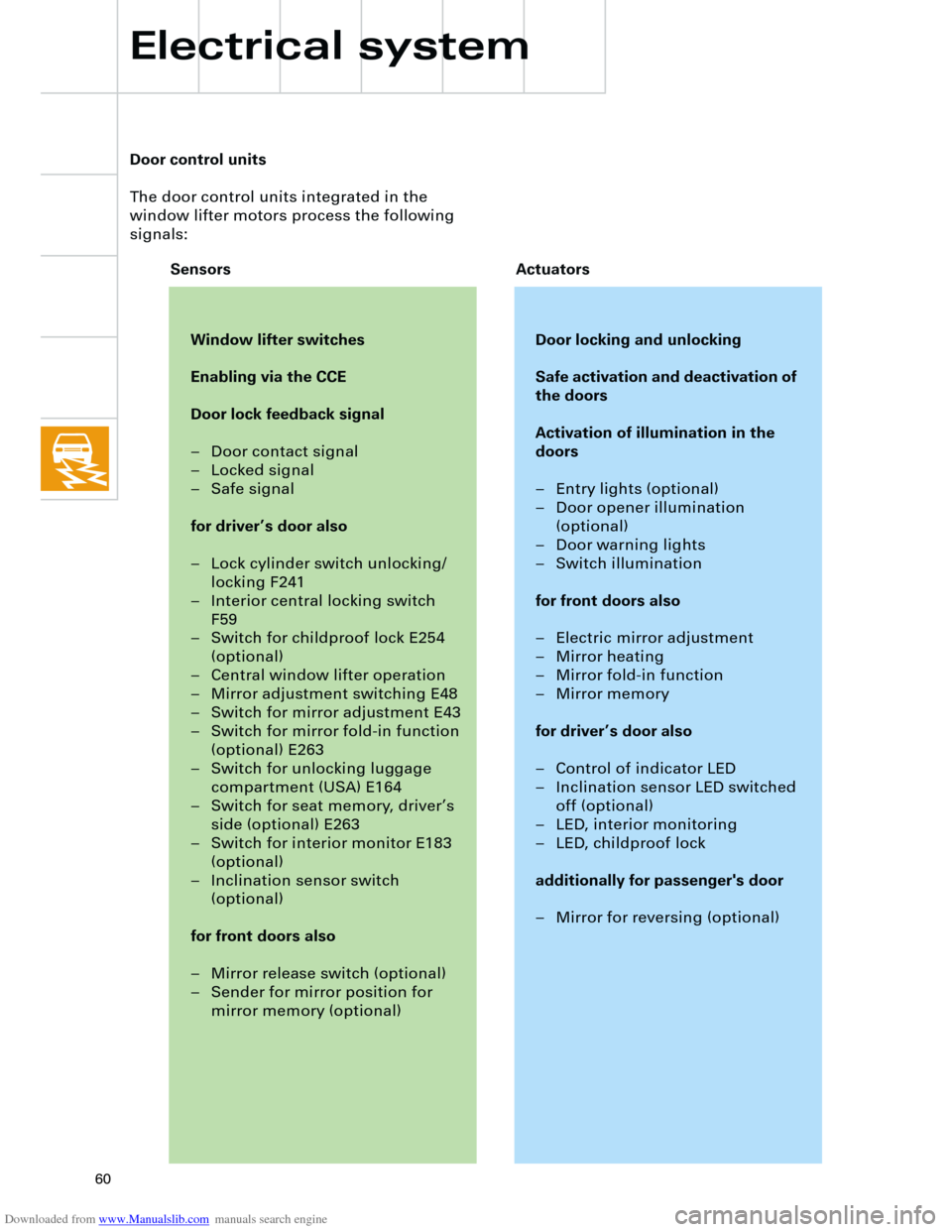
Door control units
The door control units integrated in the
window lifter motors process the following
signals:
Window lifter switches
Enabling via the CCE
Door lock feedback signal
– Door contact signal
– Locked signal
– Safe signal
for driver’s door also
– Lock cylinder switch unlocking/
locking F241
– Interior central locking switch
F59
– Switch for childproof lock E254
(optional)
– Central window lifter operation
– Mirror adjustment switching E48
– Switch for mirror adjustment E43
– Switch for mirror fold-in function
(optional) E263
– Switch for unlocking luggage
compartment (USA) E164
– Switch for seat memory, driver’s
side (optional) E263
– Switch for interior monitor E183
(optional)
– Inclination sensor switch
(optional)
for front doors also
– Mirror release switch (optional)
– Sender for mirror position for
mirror memory (optional)
Door locking and unlocking
Safe activation and deactivation of
the doors
Activation of illumination in the
doors
– Entry lights (optional)
– Door opener illumination
(optional)
– Door warning lights
– Switch illumination
for front doors also
– Electric mirror adjustment
– Mirror heating
– Mirror fold-in function
– Mirror memory
for driver’s door also
– Control of indicator LED
– Inclination sensor LED switched
off (optional)
– LED, interior monitoring
– LED, childproof lock
additionally for passenger's door
– Mirror for reversing (optional)
Sensors Actuators
Electrical system
Page 62 of 88
Downloaded from www.Manualslib.com manuals search engine
62
TS
Electrical system
The Audi A4 convenience system is available
with
– Anti-theft alarm
– Ultrasonic interior monitor
– Shattered glass sensor (Avant)
– Towing protection
as optional extras.
The anti-theft alarm is only activated when
the vehicle is locked via the radio remote con-
trol and by closing the driver's door.Deactivation is performed by
– opening the vehicle via the radio remote
control or
– opening the vehicle via the driver’s door
lock cylinder and switching on the ignition
within 15 seconds. If this time period is not
observed or if the key used is not stored in
the immobiliser, the alarm is triggered.
Data exchange between the immobiliser in
the dash panel insert and the central conven-
ience electronics takes place via the conven-
ience data bus.
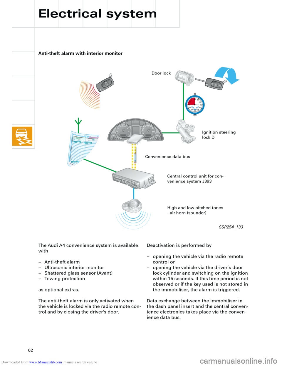
Anti-theft alarm with interior monitor
High and low pitched tones
- air horn (sounder) Central control unit for con-
venience system J393Ignition steering
lock D Door lock
Convenience data bus
SSP254_133
Page 63 of 88
Downloaded from www.Manualslib.com manuals search engine
63
An innovation in the anti-theft alarm is that a
sounder with an integrated battery is fitted in
place of the horn.
This enables the alarm to sound even when
the power supply has been interrupted.
The ultrasonic interior monitor and the tow-
ing protection can be switched off from
inside the passenger compartment by means
of a switch.
Diagnostics
The angles of the both the longitudinal and
transversal inclination of the inclination sen-
sor are displayed in the measured value
block.
SSP254_134
SSP254_135
Page 64 of 88
Downloaded from www.Manualslib.com manuals search engine
64
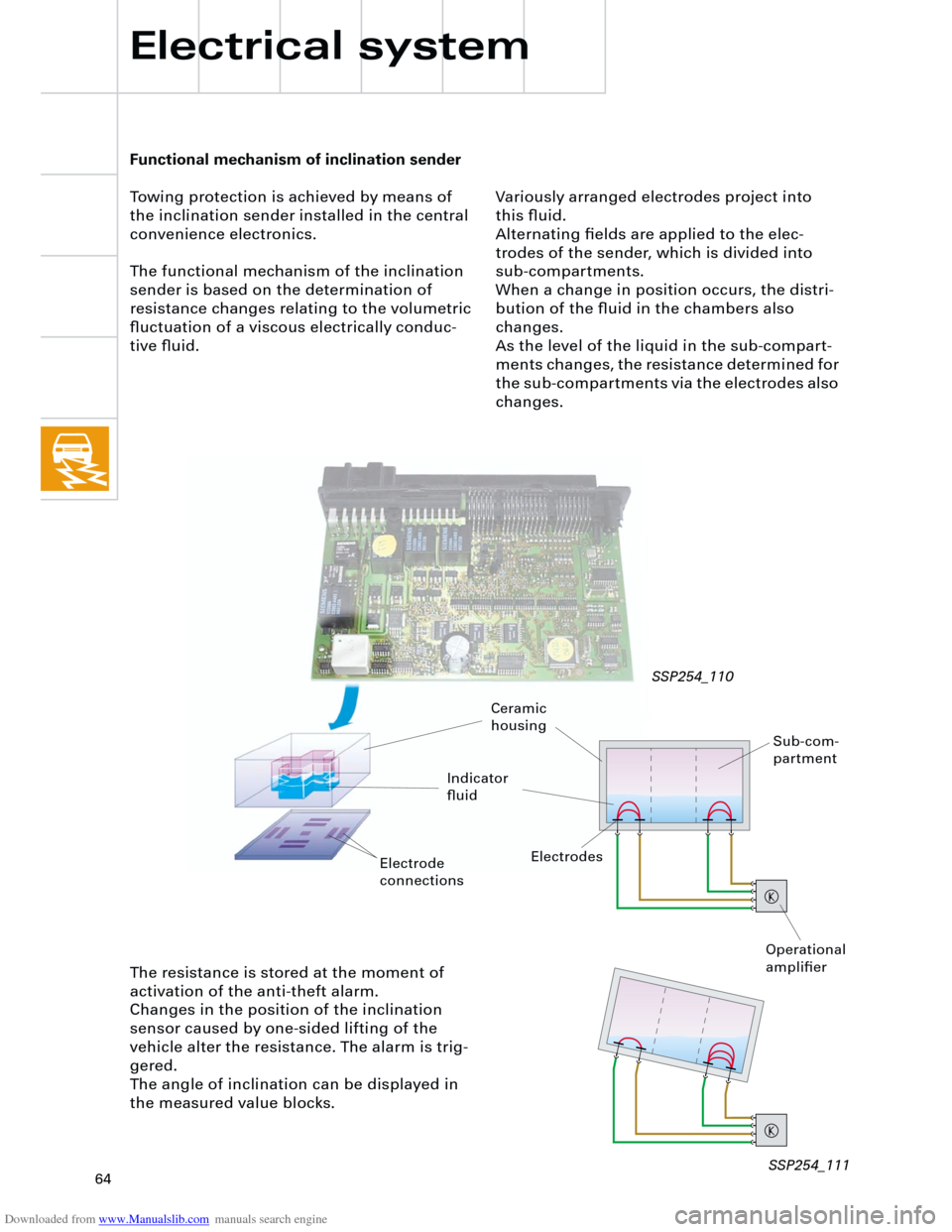
Functional mechanism of inclination sender
Towing protection is achieved by means of
the inclination sender installed in the central
convenience electronics.
The functional mechanism of the inclination
sender is based on the determination of
resistance changes relating to the volumetric
fluctuation of a viscous electrically conduc-
tive fluid.
Electrical system
SSP254_110
The resistance is stored at the moment of
activation of the anti-theft alarm.
Changes in the position of the inclination
sensor caused by one-sided lifting of the
vehicle alter the resistance. The alarm is trig-
gered.
The angle of inclination can be displayed in
the measured value blocks.
Sub-com-
partment
Ceramic
housing
Indicator
fluid
Electrodes
Operational
amplifier
Variously arranged electrodes project into
this fluid.
Alternating fields are applied to the elec-
trodes of the sender, which is divided into
sub-compartments.
When a change in position occurs, the distri-
bution of the fluid in the chambers also
changes.
As the level of the liquid in the sub-compart-
ments changes, the resistance determined for
the sub-compartments via the electrodes also
changes.
Electrode
connections
SSP254_111
Page 65 of 88
Downloaded from www.Manualslib.com manuals search engine
65
Radio chorus II, concert II and symphony II
In the new Audi A4, the new generation of
radios, chorus II, concert II and symphony II
are available as options.
The following functions have been optimised:
– AM has been extended to include long
wave.
– There are now 12 programmable stations
for AM and FM.
All three radio versions are compatible with
the external CD changer (optional).
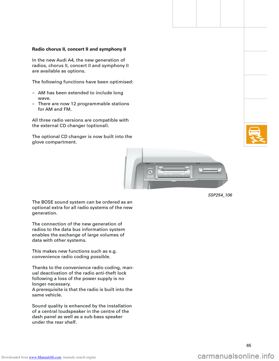
The optional CD changer is now built into the
glove compartment.
The BOSE sound system can be ordered as an
optional extra for all radio systems of the new
generation.
The connection of the new generation of
radios to the data bus information system
enables the exchange of large volumes of
data with other systems.
This makes new functions such as e.g.
convenience radio coding possible.
Thanks to the convenience radio coding, man-
ual deactivation of the radio anti-theft lock
following a loss of the power supply is no
longer necessary.
A prerequisite is that the radio is built into the
same vehicle.
Sound quality is enhanced by the installation
of a central loudspeaker in the centre of the
dash panel as well as a sub-bass speaker
under the rear shelf.
AIRBAG
OFFON
Audicd chargerCOMPAKTAKTDIGITAL AUDIOAL AUDIO
LOAD
SSP254_106
Page 72 of 88
Downloaded from www.Manualslib.com manuals search engine
72
TS
TS
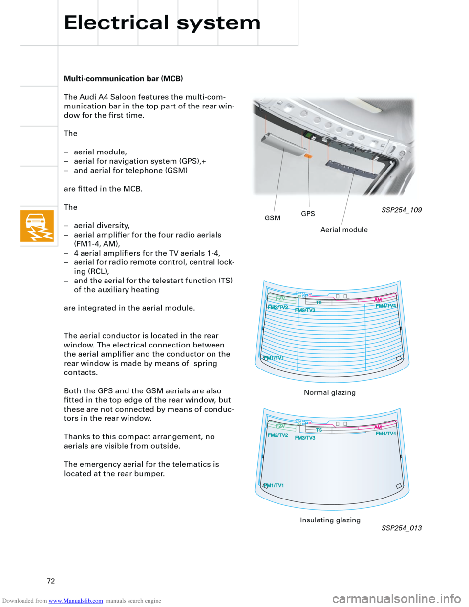
Multi-communication bar (MCB)
The Audi A4 Saloon features the multi-com-
munication bar in the top part of the rear win-
dow for the first time.
The
– aerial module,
– aerial for navigation system (GPS),+
– and aerial for telephone (GSM)
are fitted in the MCB.
The
– aerial diversity,
– aerial amplifier for the four radio aerials
(FM1-4, AM),
– 4 aerial amplifiers for the TV aerials 1-4,
– aerial for radio remote control, central lock-
ing (RCL),
– and the aerial for the telestart function (TS)
of the auxiliary heating
are integrated in the aerial module.
The aerial conductor is located in the rear
window. The electrical connection between
the aerial amplifier and the conductor on the
rear window is made by means of spring
contacts.
Both the GPS and the GSM aerials are also
fitted in the top edge of the rear window, but
these are not connected by means of conduc-
tors in the rear window.
Thanks to this compact arrangement, no
aerials are visible from outside.
The emergency aerial for the telematics is
located at the rear bumper.
Electrical system
SSP254_109
SSP254_013
GSMGPS
Aerial module
Normal glazing
Insulating glazing
Page 73 of 88
Downloaded from www.Manualslib.com manuals search engine
73
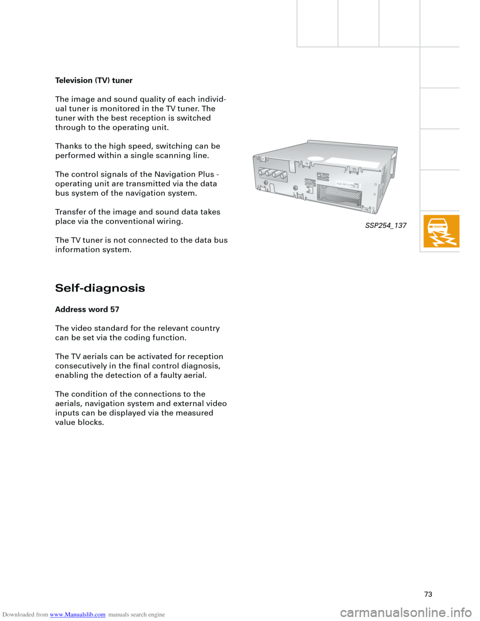
Television (TV) tuner
The image and sound quality of each individ-
ual tuner is monitored in the TV tuner. The
tuner with the best reception is switched
through to the operating unit.
Thanks to the high speed, switching can be
performed within a single scanning line.
The control signals of the Navigation Plus -
operating unit are transmitted via the data
bus system of the navigation system.
Transfer of the image and sound data takes
place via the conventional wiring.
The TV tuner is not connected to the data bus
information system.
Self-diagnosis
Address word 57
The video standard for the relevant country
can be set via the coding function.
The TV aerials can be activated for reception
consecutively in the final control diagnosis,
enabling the detection of a faulty aerial.
The condition of the connections to the
aerials, navigation system and external video
inputs can be displayed via the measured
value blocks.
SSP254_137