2001 AUDI A4 ESP
[x] Cancel search: ESPPage 36 of 88
Downloaded from www.Manualslib.com manuals search engine
36
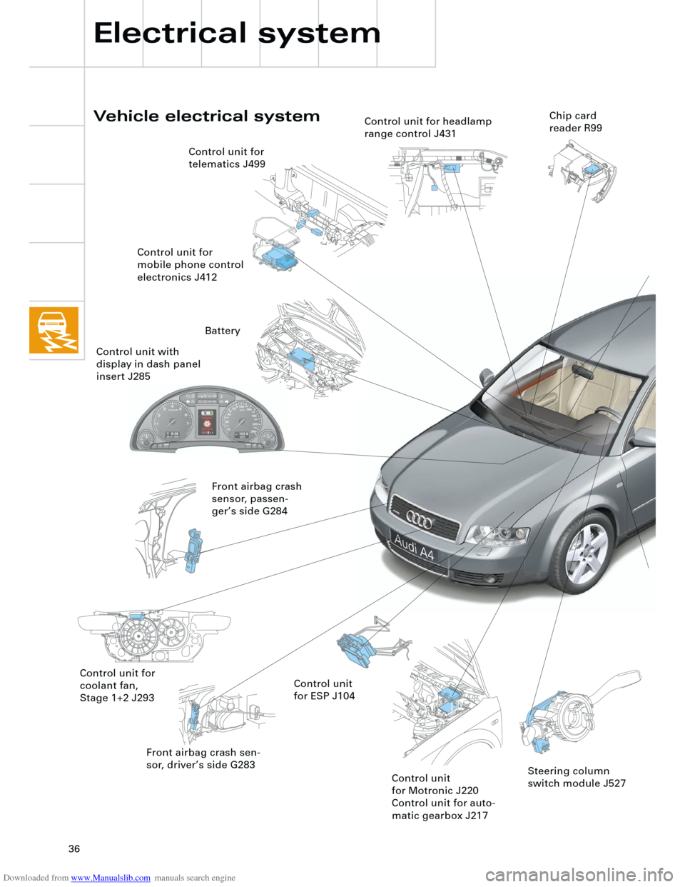
Front airbag crash sen-
sor, driver’s side G283
Vehicle electrical system
Electrical system
Control unit for
coolant fan,
Stage 1+2 J293Control unit
for ESP J104 Control unit for
telematics J499
Control unit for
mobile phone control
electronics J412
Front airbag crash
sensor, passen-
ger’s side G284
Control unit
for Motronic J220
Control unit for auto-
matic gearbox J217
Control unit for headlamp
range control J431Chip card
reader R99
Steering column
switch module J527
Battery
Control unit with
display in dash panel
insert J285
Page 37 of 88
Downloaded from www.Manualslib.com manuals search engine
37
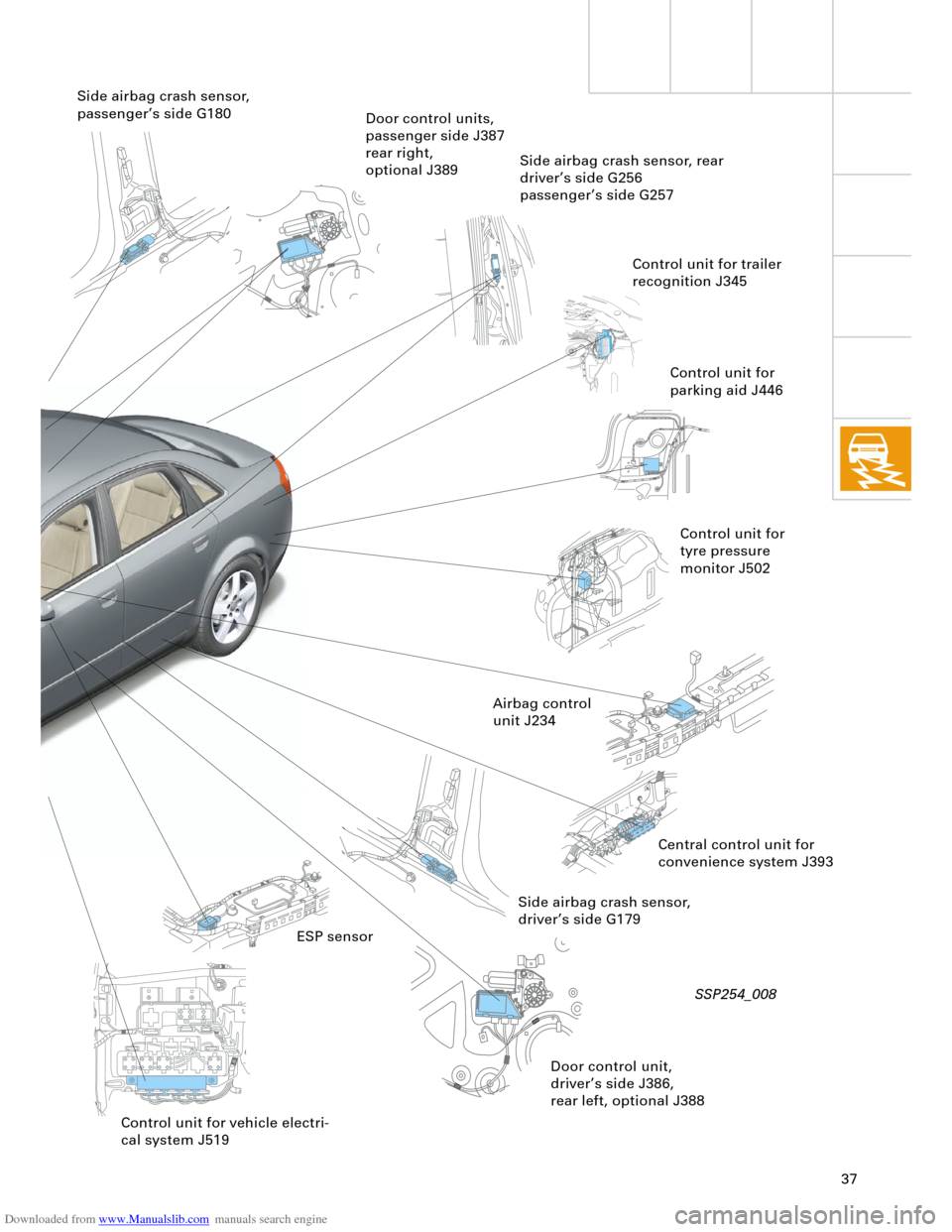
Side airbag crash sensor,
driver’s side G179
Control unit for
parking aid J446
Airbag control
unit J234Side airbag crash sensor, rear
driver’s side G256
passenger’s side G257
Control unit for
tyre pressure
monitor J502
SSP254_008
Door control units,
passenger side J387
rear right,
optional J389
ESP sensor
Control unit for trailer
recognition J345
Central control unit for
convenience system J393
Side airbag crash sensor,
passenger’s side G180
Door control unit,
driver’s side J386,
rear left, optional J388
Control unit for vehicle electri-
cal system J519
Page 39 of 88
Downloaded from www.Manualslib.com manuals search engine
39
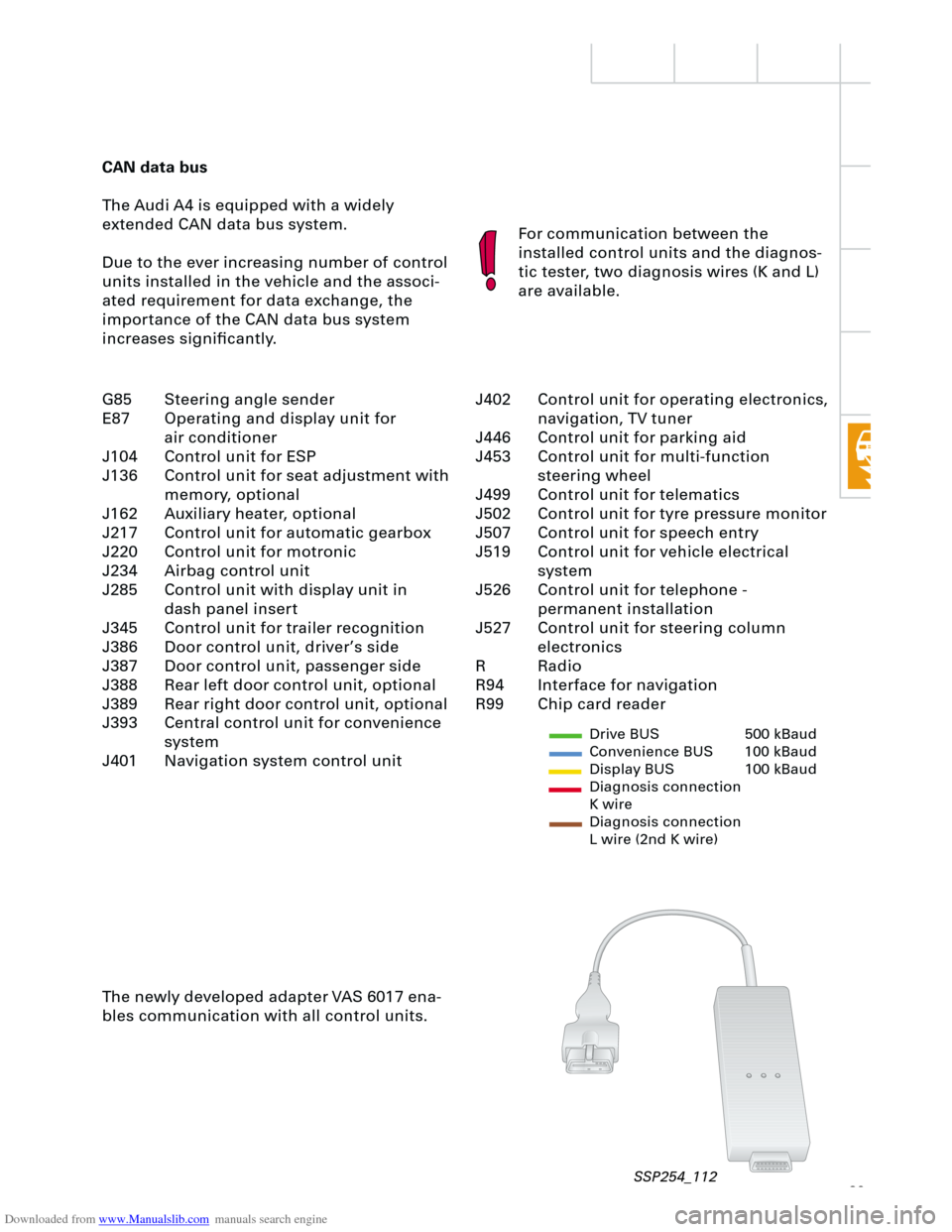
CAN data bus
The Audi A4 is equipped with a widely
extended CAN data bus system.
Due to the ever increasing number of control
units installed in the vehicle and the associ-
ated requirement for data exchange, the
importance of the CAN data bus system
increases significantly.For communication between the
installed control units and the diagnos-
tic tester, two diagnosis wires (K and L)
are available.
The newly developed adapter VAS 6017 ena-
bles communication with all control units.
Drive BUS 500 kBaud
Convenience BUS 100 kBaud
Display BUS 100 kBaud
Diagnosis connection
K wire
Diagnosis connection
L wire (2nd K wire)
J402 Control unit for operating electronics,
navigation, TV tuner
J446 Control unit for parking aid
J453 Control unit for multi-function
steering wheel
J499 Control unit for telematics
J502 Control unit for tyre pressure monitor
J507 Control unit for speech entry
J519 Control unit for vehicle electrical
system
J526 Control unit for telephone -
permanent installation
J527 Control unit for steering column
electronics
R Radio
R94 Interface for navigation
R99 Chip card reader G85 Steering angle sender
E87 Operating and display unit for
air conditioner
J104 Control unit for ESP
J136 Control unit for seat adjustment with
memory, optional
J162 Auxiliary heater, optional
J217 Control unit for automatic gearbox
J220 Control unit for motronic
J234 Airbag control unit
J285 Control unit with display unit in
dash panel insert
J345 Control unit for trailer recognition
J386 Door control unit, driver’s side
J387 Door control unit, passenger side
J388 Rear left door control unit, optional
J389 Rear right door control unit, optional
J393 Central control unit for convenience
system
J401 Navigation system control unit
SSP254_112
Page 44 of 88
Downloaded from www.Manualslib.com manuals search engine
44
Electrical system
Steering column switch
module
Due to the compact design of the newly
developed steering column switch module, it
was possible to minimise the amount of wir-
ing necessary and the space requirements.
A self-diagnosis facility for the steering col-
umn switch is now available with new switch
module.
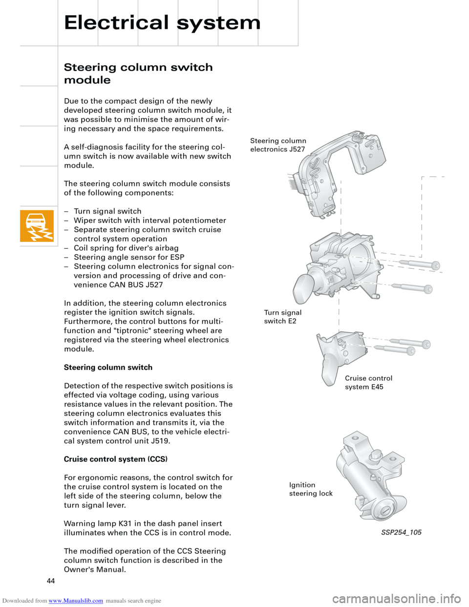
The steering column switch module consists
of the following components:
– Turn signal switch
– Wiper switch with interval potentiometer
– Separate steering column switch cruise
control system operation
– Coil spring for diver's airbag
– Steering angle sensor for ESP
– Steering column electronics for signal con-
version and processing of drive and con-
venience CAN BUS J527
In addition, the steering column electronics
register the ignition switch signals.
Furthermore, the control buttons for multi-
function and "tiptronic" steering wheel are
registered via the steering wheel electronics
module.
Steering column switch
Detection of the respective switch positions is
effected via voltage coding, using various
resistance values in the relevant position. The
steering column electronics evaluates this
switch information and transmits it, via the
convenience CAN BUS, to the vehicle electri-
cal system control unit J519.
Cruise control system (CCS)
For ergonomic reasons, the control switch for
the cruise control system is located on the
left side of the steering column, below the
turn signal lever.
Warning lamp K31 in the dash panel insert
illuminates when the CCS is in control mode.
The modified operation of the CCS Steering
column switch function is described in the
Owner's Manual.
Cruise control
system E45
Ignition
steering lock Steering column
electronics J527
Turn signal
switch E2
SSP254_105
Page 45 of 88
Downloaded from www.Manualslib.com manuals search engine
45
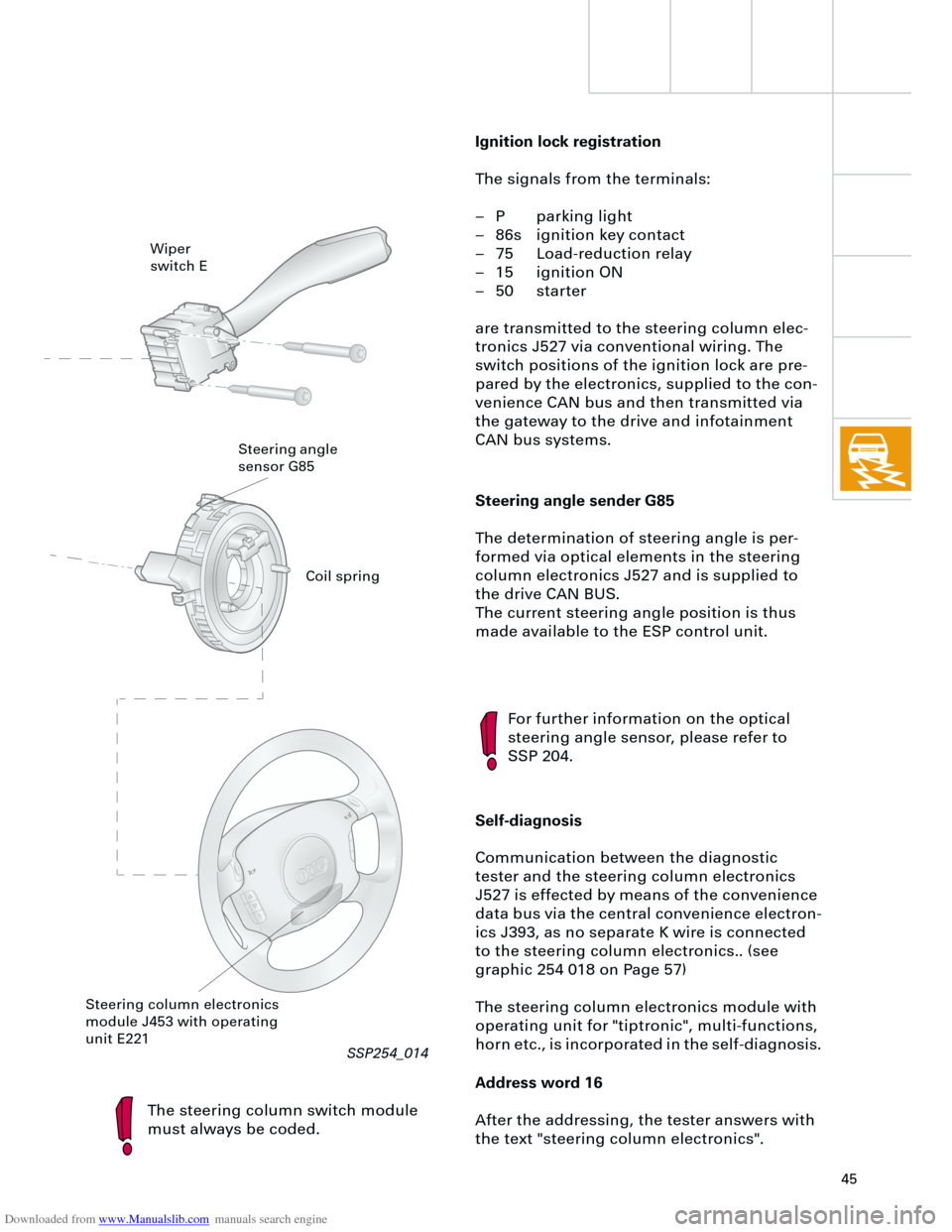
Steering angle sender G85
The determination of steering angle is per-
formed via optical elements in the steering
column electronics J527 and is supplied to
the drive CAN BUS.
The current steering angle position is thus
made available to the ESP control unit.
The steering column switch module
must always be coded.
For further information on the optical
steering angle sensor, please refer to
SSP 204.
Self-diagnosis
Communication between the diagnostic
tester and the steering column electronics
J527 is effected by means of the convenience
data bus via the central convenience electron-
ics J393, as no separate K wire is connected
to the steering column electronics.. (see
graphic 254 018 on Page 57)
The steering column electronics module with
operating unit for "tiptronic", multi-functions,
horn etc., is incorporated in the self-diagnosis.
Address word 16
After the addressing, the tester answers with
the text "steering column electronics".
Wiper
switch E
Steering angle
sensor G85
Steering column electronics
module J453 with operating
unit E221
Ignition lock registration
The signals from the terminals:
– P parking light
– 86s ignition key contact
– 75 Load-reduction relay
– 15 ignition ON
– 50 starter
are transmitted to the steering column elec-
tronics J527 via conventional wiring. The
switch positions of the ignition lock are pre-
pared by the electronics, supplied to the con-
venience CAN bus and then transmitted via
the gateway to the drive and infotainment
CAN bus systems.
Coil spring
RT
SSP254_014
Page 66 of 88
Downloaded from www.Manualslib.com manuals search engine
66
In order to improve sound quality, acoustic
curves related to vehicle type are stored in the
concert II and symphony II radios.
The acoustic curves are set in the control unit
coding function of the radio systems.
In addition, the sound settings for the FM, AM
and CD modes are stored separately in the
concert II and symphony II radios. Conse-
quently, the various level controls do not
require resetting each time the driver
changes modes.
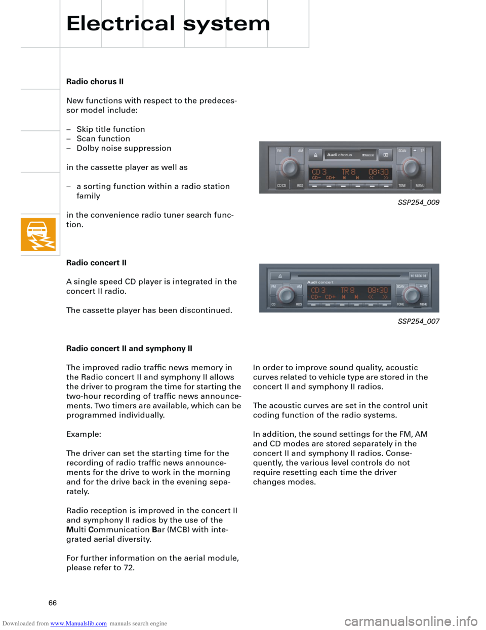
Radio chorus II
New functions with respect to the predeces-
sor model include:
– Skip title function
– Scan function
– Dolby noise suppression
in the cassette player as well as
– a sorting function within a radio station
family
in the convenience radio tuner search func-
tion.
Radio concert II
A single speed CD player is integrated in the
concert II radio.
The cassette player has been discontinued.
Radio concert II and symphony II
The improved radio traffic news memory in
the Radio concert II and symphony II allows
the driver to program the time for starting the
two-hour recording of traffic news announce-
ments. Two timers are available, which can be
programmed individually.
Example:
The driver can set the starting time for the
recording of radio traffic news announce-
ments for the drive to work in the morning
and for the drive back in the evening sepa-
rately.
Radio reception is improved in the concert II
and symphony II radios by the use of the
M
ulti
C
ommunication
B
ar (MCB) with inte-
grated aerial diversity.
For further information on the aerial module,
please refer to 72.
Electrical system
SSP254_009
SSP254_007
Page 80 of 88
Downloaded from www.Manualslib.com manuals search engine
80
Heater/AC
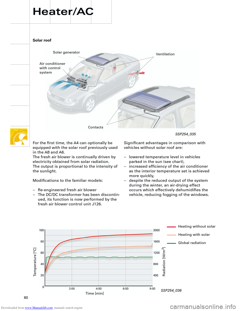
Significant advantages in comparison with
vehicles without solar roof are:
– lowered temperature level in vehicles
parked in the sun (see chart),
– increased efficiency of the air conditioner
as the interior temperature set is achieved
more quickly,
– despite the reduced output of the system
during the winter, an air-drying effect
occurs which effectively dehumidifies the
vehicle, reducing fogging of the windows.
Solar roof
For the first time, the A4 can optionally be
equipped with the solar roof previously used
in the A8 and A6.
The fresh air blower is continually driven by
electricity obtained from solar radiation.
The output is proportional to the intensity of
the sunlight.
Modifications to the familiar models:
– Re-engineered fresh air blower
– The DC/DC transformer has been discontin-
ued, its function is now performed by the
fresh air blower control unit J126.
Time [min]
Temperature [°C]
Radiation [W/m
2
]
Ventilation
Air conditioner
with control
systemSolar generator
SSP254_035
SSP254_036
Contacts
Heating without solar
Heating with solar
Global radiation
Page 86 of 88
Downloaded from www.Manualslib.com manuals search engine
86
+ -
K
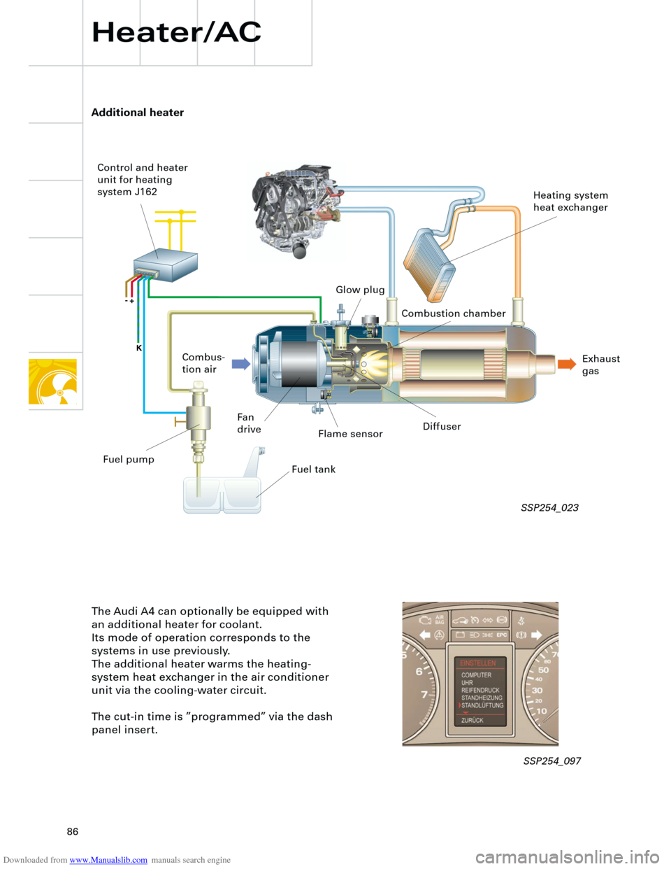
Additional heater
Heater/AC
The Audi A4 can optionally be equipped with
an additional heater for coolant.
Its mode of operation corresponds to the
systems in use previously.
The additional heater warms the heating-
system heat exchanger in the air conditioner
unit via the cooling-water circuit.
The cut-in time is ”programmed” via the dash
panel insert.
Flame sensor
Fan
driveDiffuser
Fuel tank Combus-
tion air Control and heater
unit for heating
system J162
Heating system
heat exchanger
Exhaust
gas Combustion chamber Glow plug
Fuel pump
SSP254_023
SSP254_097