2000 YAMAHA YZF600 light
[x] Cancel search: lightPage 23 of 109
INSTRUMENT AND CONTROL FUNCTIONS
3-9
3
EAU00138
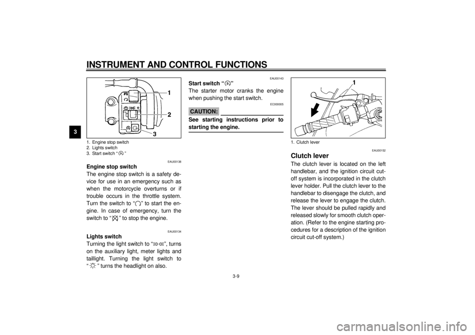
Engine stop switch
The engine stop switch is a safety de-
vice for use in an emergency such as
when the motorcycle overturns or if
trouble occurs in the throttle system.
Turn the switch to “ ” to start the en-
gine. In case of emergency, turn the
switch to “ ” to stop the engine.
EAU00134
Lights switch
Turning the light switch to “ ”, turns
on the auxiliary light, meter lights and
taillight. Turning the light switch to
“ ” turns the headlight on also.
EAU00143
Start switch “ ”
The starter motor cranks the engine
when pushing the start switch.
EC000005
CAUTION:@ See starting instructions prior to
starting the engine. @
EAU00152
Clutch leverThe clutch lever is located on the left
handlebar, and the ignition circuit cut-
off system is incorporated in the clutch
lever holder. Pull the clutch lever to the
handlebar to disengage the clutch, and
release the lever to engage the clutch.
The lever should be pulled rapidly and
released slowly for smooth clutch oper-
ation. (Refer to the engine starting pro-
cedures for a description of the ignition
circuit cut-off system.)
1. Engine stop switch
2. Lights switch
3. Start switch “ ”
1. Clutch lever
E_4tv_Functions.fm Page 9 Wednesday, September 1, 1999 11:10 AM
Page 40 of 109
PRE-OPERATION CHECKS
4-2
4
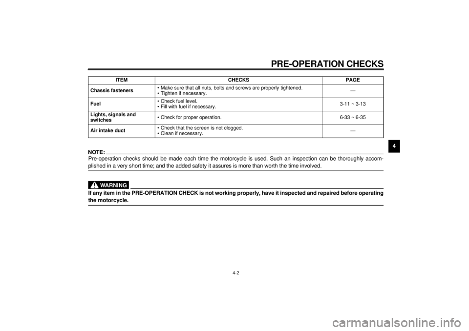
NOTE:Pre-operation checks should be made each time the motorcycle is used. Such an inspection can be thoroughly accom-
plished in a very short time; and the added safety it assures is more than worth the time involved.
WARNING
If any item in the PRE-OPERATION CHECK is not working properly, have it inspected and repaired before operating
the motorcycle.Chassis fasteners• Make sure that all nuts, bolts and screws are properly tightened.
• Tighten if necessary.—
Fuel• Check fuel level.
• Fill with fuel if necessary.3-11 ~ 3-13
Lights, signals and
switches• Check for proper operation. 6-33 ~ 6-35
Air intake duct• Check that the screen is not clogged.
• Clean if necessary.— ITEM CHECKS PAGE
E_4tv_Preop.fm Page 2 Wednesday, September 1, 1999 11:11 AM
Page 45 of 109
OPERATION AND IMPORTANT RIDING POINTS
5-3
51. Turn the main switch to “ON” and
the engine stop switch to “ ”.
EC000035
CAUTION:@ If the fuel indicator light comes on,
check the fuel level. If necessary, fill
the tank with fuel. @2. Shift the transmission into neutral.NOTE:@ When the transmission is in neutral, the
neutral indicator light should be on. If
the light does not come on, ask a
Yamaha dealer to inspect it. @3. Turn on the starter (choke) and
completely close the throttle grip.
4. Start the engine by pushing the
start switch.
NOTE:@ If the engine fails to start, release the
start switch, wait a few seconds, then
try again. Each attempt should be as
short as possible to preserve the bat-
tery. Do not crank the engine more
than 10 seconds on any one attempt. @
EC000036
CAUTION:@ The oil level indicator light and fuel
indicator light should come on when
the start switch is pushed and
should go off when the start switch
is released. If the oil level indicator
light flickers or remains on, immedi-
ately stop the engine and check the
engine oil level and for oil leakage. If
necessary, fill the engine with oil
and check to see that the oil level in-
dicator light goes off. If not, consult
a Yamaha dealer. @
5. After starting the engine, move the
starter (choke) to the halfway posi-
tion.NOTE:@ For maximum engine life, never accel-
erate hard with a cold engine! @6. After the engine is warm, turn off
the starter (choke) completely.NOTE:@ The engine is warm when it responds
normally to the throttle with the starter
(choke) turned off. @
E_4tv_Operation.fm Page 3 Wednesday, September 1, 1999 11:11 AM
Page 46 of 109
OPERATION AND IMPORTANT RIDING POINTS
5-4
5
EAU01258
Starting a warm engineThe starter (choke) is not required
when the engine is warm.
EC000046
CAUTION:@ See the “Engine break-in” section
prior to operating the motorcycle for
the first time. @
EAU00423
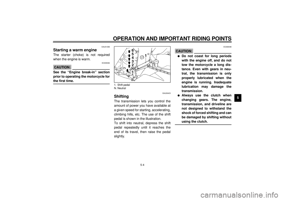
ShiftingThe transmission lets you control the
amount of power you have available at
a given speed for starting, accelerating,
climbing hills, etc. The use of the shift
pedal is shown in the illustration.
To shift into neutral, depress the shift
pedal repeatedly until it reaches the
end of its travel, then raise the pedal
slightly.
EC000048
CAUTION:@ l
Do not coast for long periods
with the engine off, and do not
tow the motorcycle a long dis-
tance. Even with gears in neu-
tral, the transmission is only
properly lubricated when the
engine is running. Inadequate
lubrication may damage the
transmission.
l
Always use the clutch when
changing gears. The engine,
transmission, and driveline are
not designed to withstand the
shock of forced shifting and can
be damaged by shifting without
using the clutch.
@
1. Shift pedal
N. Neutral
E_4tv_Operation.fm Page 4 Wednesday, September 1, 1999 11:11 AM
Page 47 of 109
OPERATION AND IMPORTANT RIDING POINTS
5-5
5
EAU02937
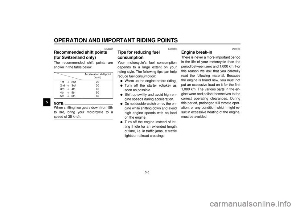
Recommended shift points
(for Switzerland only)The recommended shift points are
shown in the table below.CF-26ENOTE:@ When shifting two gears down from 5th
to 3rd, bring your motorcycle to a
speed of 35 km/h. @
EAU00424
Tips for reducing fuel
consumptionYour motorcycle’s fuel consumption
depends to a large extent on your
riding style. The following tips can help
reduce fuel consumption:l
Warm up the engine before riding.
l
Turn off the starter (choke) as
soon as possible.
l
Shift up swiftly and avoid high en-
gine speeds during acceleration.
l
Do not double-clutch or rev the en-
gine while shifting down and avoid
high engine speeds with no load
on the engine.
l
Turn off the engine instead of let-
ting it idle for an extended length
of time, i.e. in traffic jams, at traffic
lights or railroad crossings.
EAU00436
Engine break-inThere is never a more important period
in the life of your motorcycle than the
period between zero and 1,000 km. For
this reason we ask that you carefully
read the following material. Because
the engine is brand new, you must not
put an excessive load on it for the first
1,000 km. The various parts in the en-
gine wear and polish themselves to the
correct operating clearances. During
this period, prolonged full throttle oper-
ation, or any condition which might re-
sult in excessive heating of the engine,
must be avoided.
Acceleration shift point
(km/h)
1st®2nd
2nd®3rd
3rd®4th
4th®5th
5th®6th20
30
40
50
60
E_4tv_Operation.fm Page 5 Wednesday, September 1, 1999 11:11 AM
Page 50 of 109
6
PERIODIC MAINTENANCE AND MINOR REPAIR
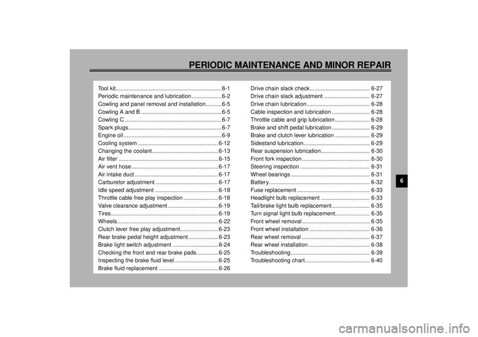
Tool kit................................................................... 6-1
Periodic maintenance and lubrication ................... 6-2
Cowling and panel removal and installation.......... 6-5
Cowling A and B ................................................... 6-5
Cowling C ............................................................. 6-7
Spark plugs........................................................... 6-7
Engine oil .............................................................. 6-9
Cooling system ................................................... 6-12
Changing the coolant.......................................... 6-13
Air filter ............................................................... 6-15
Air vent hose ....................................................... 6-17
Air intake duct ..................................................... 6-17
Carburetor adjustment ........................................ 6-17
Idle speed adjustment ........................................ 6-18
Throttle cable free play inspection ...................... 6-18
Valve clearance adjustment ................................ 6-19
Tires .................................................................... 6-19
Wheels................................................................ 6-22
Clutch lever free play adjustment........................ 6-23
Rear brake pedal height adjustment ................... 6-23
Brake light switch adjustment ............................. 6-24
Checking the front and rear brake pads.............. 6-25
Inspecting the brake fluid level............................ 6-25
Brake fluid replacement ...................................... 6-26Drive chain slack check...................................... 6-27
Drive chain slack adjustment ............................. 6-27
Drive chain lubrication........................................ 6-28
Cable inspection and lubrication ........................ 6-28
Throttle cable and grip lubrication ...................... 6-28
Brake and shift pedal lubrication ........................ 6-29
Brake and clutch lever lubrication ...................... 6-29
Sidestand lubrication.......................................... 6-29
Rear suspension lubrication............................... 6-30
Front fork inspection ........................................... 6-30
Steering inspection ............................................ 6-31
Wheel bearings .................................................. 6-31
Battery................................................................ 6-32
Fuse replacement .............................................. 6-33
Headlight bulb replacement ............................... 6-33
Tail/brake light bulb replacement ........................ 6-35
Turn signal light bulb replacement...................... 6-35
Front wheel removal ........................................... 6-35
Front wheel installation ...................................... 6-36
Rear wheel removal ........................................... 6-37
Rear wheel installation ....................................... 6-38
Troubleshooting .................................................. 6-39
Troubleshooting chart......................................... 6-40
E_4tv_PeriodicTOC.fm Page 1 Wednesday, September 1, 1999 11:11 AM
Page 56 of 109
PERIODIC MAINTENANCE AND MINOR REPAIR
6-6
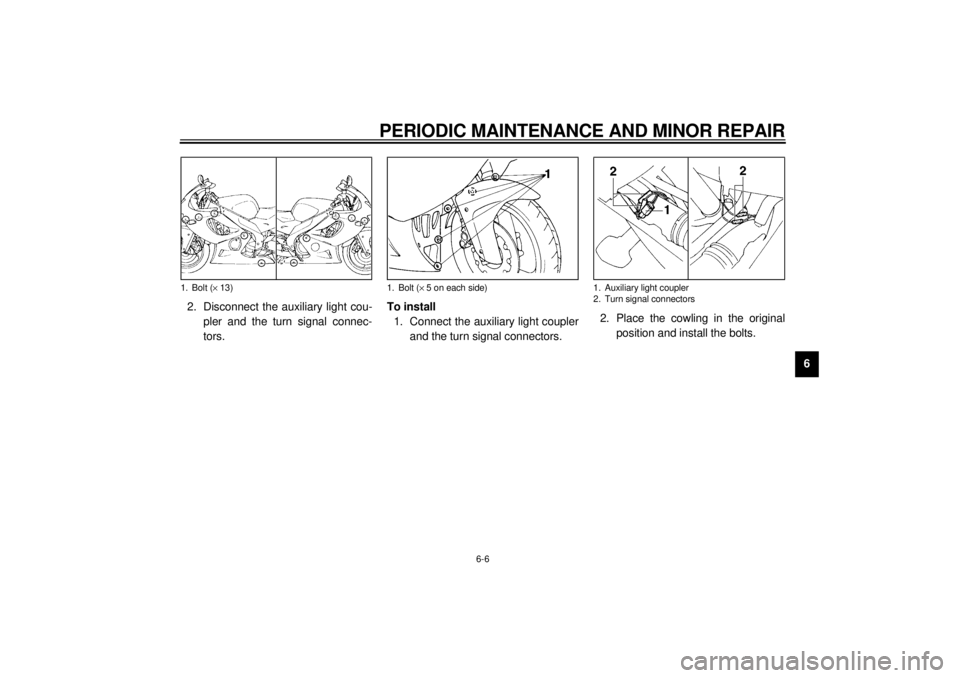
6 2. Disconnect the auxiliary light cou-
pler and the turn signal connec-
tors.To install
1. Connect the auxiliary light coupler
and the turn signal connectors.2. Place the cowling in the original
position and install the bolts.
1. Bolt (´ 13)
1. Bolt (´ 5 on each side)
1. Auxiliary light coupler
2. Turn signal connectors
E_4tv_Periodic.fm Page 6 Wednesday, September 1, 1999 11:12 AM
Page 58 of 109
PERIODIC MAINTENANCE AND MINOR REPAIR
6-8
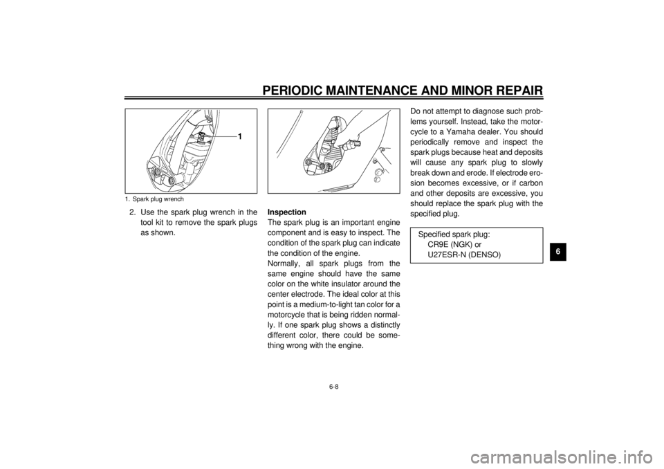
6 2. Use the spark plug wrench in the
tool kit to remove the spark plugs
as shown.Inspection
The spark plug is an important engine
component and is easy to inspect. The
condition of the spark plug can indicate
the condition of the engine.
Normally, all spark plugs from the
same engine should have the same
color on the white insulator around the
center electrode. The ideal color at this
point is a medium-to-light tan color for a
motorcycle that is being ridden normal-
ly. If one spark plug shows a distinctly
different color, there could be some-
thing wrong with the engine.Do not attempt to diagnose such prob-
lems yourself. Instead, take the motor-
cycle to a Yamaha dealer. You should
periodically remove and inspect the
spark plugs because heat and deposits
will cause any spark plug to slowly
break down and erode. If electrode ero-
sion becomes excessive, or if carbon
and other deposits are excessive, you
should replace the spark plug with the
specified plug.
1. Spark plug wrench
Specified spark plug:
CR9E (NGK) or
U27ESR-N (DENSO)
E_4tv_Periodic.fm Page 8 Wednesday, September 1, 1999 11:12 AM