Page 71 of 103

PERIODIC MAINTENANCE AND MINOR REPAIR
6-23
6
EAU00744
Drive chain slack checkNOTE:@ Spin the wheel several times and find
the tightest position of the chain. Check
and/or adjust the chain slack while it’s
in this tightest position. @To check the chain slack the motor-
cycle must be held straight up with both
wheels on the ground and without rider.
Check the slack at the position shown
in the illustration. Normal slack is ap-
proximately 20 ~ 35 mm. If the slack
exceeds 35 mm, adjust.
EAU01251
Drive chain slack adjustment1. Loosen the axle nut.
2. Loosen the locknuts on each side.
To tighten the chain, turn the chain
adjusting bolts in direction a
. To
loosen the chain, turn the adjust-
ing bolts in direction b
and push
the wheel forward. Turn each ad-
justing bolt exactly the same
amount to maintain correct axle
alignment. There are marks oneach side of the swingarm. Use
these marks to align the rear
wheel.
EC000096
CAUTION:@ Too little chain slack will overload
the engine and other vital parts.
Keep the slack within the specified
limits. @3. After adjusting, tighten the lock-
nuts. Then tighten the axle nut to
the specified torque.
a. Drive chain slack
1. Axle nut
2. Adjusting bolt
3. Locknut
4. Alignment marks
Tightening torque:
Axle nut:
150 Nm (15 m·kg)
E_4sv_Periodic.fm Page 23 Tuesday, August 31, 1999 3:45 PM
Page 80 of 103

PERIODIC MAINTENANCE AND MINOR REPAIR
6-32
6 4. Install the calipers, caliper bolts
and brake hose holders. Make
sure there is enough gap between
the brake pads before installing
the calipers onto the brake discs.
5. Tighten the wheel axle, pinch bolt
and caliper bolts to the specified
torques.
6. Push down hard on the handle-
bars several times to check for
proper fork operation.
7. Install the speedometer cable.
8. Install the front fender and bolts.
EAU01247*
Rear wheel removal
EW000122
WA R N I N G
@ l
It is advisable to have a Yamaha
dealer service the wheel.
l
Securely support the motor-
cycle so there is no danger of it
falling over.
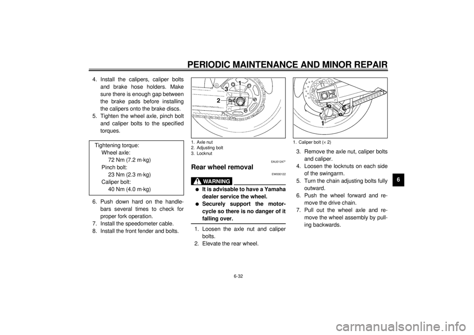
@1. Loosen the axle nut and caliper
bolts.
2. Elevate the rear wheel.3. Remove the axle nut, caliper bolts
and caliper.
4. Loosen the locknuts on each side
of the swingarm.
5. Turn the chain adjusting bolts fully
outward.
6. Push the wheel forward and re-
move the drive chain.
7. Pull out the wheel axle and re-
move the wheel assembly by pull-
ing backwards. Tightening torque:
Wheel axle:
72 Nm (7.2 m·kg)
Pinch bolt:
23 Nm (2.3 m·kg)
Caliper bolt:
40 Nm (4.0 m·kg)1. Axle nut
2. Adjusting bolt
3. Locknut
1. Caliper bolt (´ 2)
E_4sv_Periodic.fm Page 32 Tuesday, August 31, 1999 3:45 PM
Page 81 of 103
PERIODIC MAINTENANCE AND MINOR REPAIR
6-33
6
NOTE:@ l
Do not depress the brake pedal
when the caliper is off the disc as
the brake pads will be forced shut.
l
You do not have to disassemble
the chain in order to remove or in-
stall the rear wheel.
@
EAU01246*
Rear wheel installation1. Install the wheel assembly, caliper
bracket and insert the axle.
2. Install and adjust the drive chain.
(See page 6-23 for details about
adjusting the drive chain slack.)
3. Install the axle nut and let the
motorcycle down.
4. Install the caliper and caliper bolts.
Make sure there is enough gap
between the brake pads before in-
stalling the caliper onto the brake
disc.
5. Tighten the axle nut and caliper
bolts to the specified torques.1. Caliper bracket
Tightening torque:
Axle nut:
150 Nm (15.0 m·kg)
Caliper bolt:
40 Nm (4.0 m·kg)
E_4sv_Periodic.fm Page 33 Tuesday, August 31, 1999 3:45 PM