Page 26 of 95
INSTRUMENT AND CONTROL FUNCTIONS
3-12
3
EAU03032
Starter (choke) knobStarting a cold engine requires a richer
air-fuel mixture, which is supplied by
the starter (choke).
Move the knob in direction
a to turn on
the starter (choke).
Move the knob in direction
b to turn off
the starter (choke).
EAU01214*
Steering lockOn the right side of the headpipe, there
is a place to lock the steering with a
padlock. Turn the handlebars to align
the holes in the two brackets and lock
the steering with a suitable padlock.
E_5ja_Functions.fm Page 12 Saturday, October 16, 1999 10:10 AM
Page 27 of 95
INSTRUMENT AND CONTROL FUNCTIONS
3-13
3
EAU01737
Rider seatTo remove
Insert the key into the main switch and
turn it counterclockwise to the “OPEN”
position. Then, remove the seat by pull-
ing it upward.NOTE:@ Do not push inward when turning the
key. @
To install
Insert the projection on the rear of the
seat into the holder, then push the front
of the seat downward until it locks and
remove the key from the main switch.NOTE:@ Make sure the seat is securely installed
before riding the motorcycle. @
EAU01819*
Helmet holderThe helmet holder is located under the
rider seat.
Remove the rider seat and hook the
helmet on the helmet holder. Then, in-
stall the seat.
EW000030
WARNING
@ Never ride with a helmet in the hel-
met holder. The helmet may hit ob-
jects, causing loss of control and
possibly an accident. @
1. Projection
2. Seat holder
1. Helmet holder
E_5ja_Functions.fm Page 13 Saturday, October 16, 1999 10:10 AM
Page 28 of 95
INSTRUMENT AND CONTROL FUNCTIONS
3-14
3
EAU01694
Adjusting rear shock
absorber preloadThis shock absorber is equipped with a
spring preload adjusting nut. Use the
special wrench located in the owner’s
tool kit to adjust the spring preload.
1. Loosen the locknut.2. Turn the adjusting nut in
direction
a to increase spring pre-
load and in direction
b to de-
crease spring preload. The spring
preload is determined by the
spring set length.
Shortening the spring set length
increases spring preload, length-
ening the spring set length de-
creases spring preload.
EC000015
CAUTION:@ Never attempt to turn an adjuster
beyond the maximum or minimum
setting. @
1. Locknut
2. Adjusting nut
1. Special wrench
A. Distance “A”Spring preload:
Minimum (soft):
Distance “A” = 42.5 mm
Standard:
Distance “A” = 42.5 mm
Maximum (hard):
Distance “A” = 51.5 mm
E_5ja_Functions.fm Page 14 Saturday, October 16, 1999 10:10 AM
Page 29 of 95

INSTRUMENT AND CONTROL FUNCTIONS
3-15
33. Tighten the locknut to the speci-
fied torque.
EC000018
CAUTION:@ Always tighten the locknut against
the spring adjusting nut and tighten
the locknut to the specified torque. @
EAU00315
WARNING
@ This shock absorber contains high-
ly pressurized nitrogen gas. Read
and understand the following infor-
mation before handling the shock
absorber. The manufacturer cannot
be held responsible for property
damage or personal injury that may
result from improper handling.l
Do not tamper with or attempt to
open the cylinder assembly.
l
Do not subject the shock ab-
sorber to an open flame or other
high heat source. This may
cause the unit to explode due to
excessive gas pressure.
l
Do not deform or damage the
cylinder in any way. Cylinder
damage will result in poor
damping performance.
l
Take your shock absorber to a
Yamaha dealer for any service.
@
EAU00330
SidestandThis model is equipped with an ignition
circuit cut-off system. The motorcycle
must not be ridden when the sidestand
is down. The sidestand is located on
the left side of the frame. (Refer to
page 5-1 for an explanation of this sys-
tem.)
EW000044
WARNING
@ This motorcycle must not be operat-
ed with the sidestand in the down
position. If the stand is not properly
retracted, it could contact the
ground and distract the operator, re-
sulting in a possible loss of control.
Yamaha has designed into this
motorcycle a lockout system to as-
sist the operator in fulfilling the re-
sponsibility of retracting the
sidestand. Please check carefully
the operating instructions listed be-
low and if there is any indication of a
malfunction, return the motorcycle
to a Yamaha dealer immediately for
repair. @
Tightening torque:
Locknut:
35 Nm (3.5 m·kg)
E_5ja_Functions.fm Page 15 Saturday, October 16, 1999 10:10 AM
Page 61 of 95

PERIODIC MAINTENANCE AND MINOR REPAIR
6-17
6
EAU00685
WheelsTo ensure maximum performance,
long service, and safe operation, note
the following:l
Always inspect the wheels before
a ride. Check for cracks, bends or
warpage of the wheel. Be sure the
spokes are tight and undamaged.
If any abnormal condition exists in
a wheel, consult a Yamaha dealer.
Do not attempt even small repairs
to the wheel. If a wheel is de-
formed or cracked, it must be re-
placed.
l
Tires and wheels should be bal-
anced whenever either one is
changed or replaced. Failure to
have a wheel balanced can result
in poor performance, adverse han-
dling characteristics, and short-
ened tire life.
l
Ride at moderate speeds after
changing a tire since the tire sur-
face must first be broken in for it to
develop its optimal characteristics.
EAU00694
Clutch lever free play
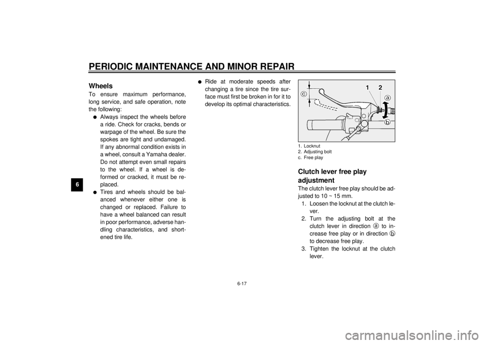
adjustmentThe clutch lever free play should be ad-
justed to 10 ~ 15 mm.
1. Loosen the locknut at the clutch le-
ver.
2. Turn the adjusting bolt at the
clutch lever in direction
a to in-
crease free play or in direction
b
to decrease free play.
3. Tighten the locknut at the clutch
lever.1. Locknut
2. Adjusting bolt
c. Free play
E_5ja_Periodic.fm Page 17 Saturday, October 16, 1999 10:12 AM
Page 62 of 95

PERIODIC MAINTENANCE AND MINOR REPAIR
6-18
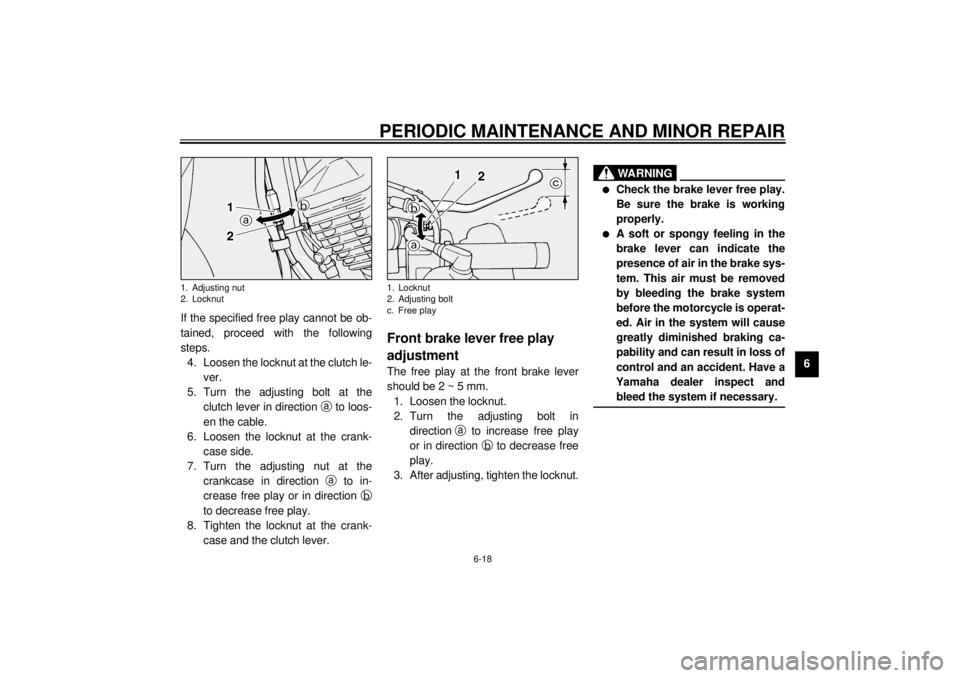
6 If the specified free play cannot be ob-
tained, proceed with the following
steps.
4. Loosen the locknut at the clutch le-
ver.
5. Turn the adjusting bolt at the
clutch lever in direction
a to loos-
en the cable.
6. Loosen the locknut at the crank-
case side.
7. Turn the adjusting nut at the
crankcase in direction
a to in-
crease free play or in direction
b
to decrease free play.
8. Tighten the locknut at the crank-
case and the clutch lever.
EAU00696
Front brake lever free play
adjustmentThe free play at the front brake lever
should be 2 ~ 5 mm.
1. Loosen the locknut.
2. Turn the adjusting bolt in
direction
a to increase free play
or in direction
b to decrease free
play.
3. After adjusting, tighten the locknut.
EW000099
WARNING
@ l
Check the brake lever free play.
Be sure the brake is working
properly.
l
A soft or spongy feeling in the
brake lever can indicate the
presence of air in the brake sys-
tem. This air must be removed
by bleeding the brake system
before the motorcycle is operat-
ed. Air in the system will cause
greatly diminished braking ca-
pability and can result in loss of
control and an accident. Have a
Yamaha dealer inspect and
bleed the system if necessary.
@
1. Adjusting nut
2. Locknut
1. Locknut
2. Adjusting bolt
c. Free play
E_5ja_Periodic.fm Page 18 Saturday, October 16, 1999 10:12 AM
Page 65 of 95

PERIODIC MAINTENANCE AND MINOR REPAIR
6-21
6
EAU00731
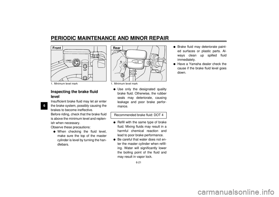
Inspecting the brake fluid
levelInsufficient brake fluid may let air enter
the brake system, possibly causing the
brakes to become ineffective.
Before riding, check that the brake fluid
is above the minimum level and replen-
ish when necessary.
Observe these precautions:l
When checking the fluid level,
make sure the top of the master
cylinder is level by turning the han-
dlebars.
l
Use only the designated quality
brake fluid. Otherwise, the rubber
seals may deteriorate, causing
leakage and poor brake perfor-
mance.
l
Refill with the same type of brake
fluid. Mixing fluids may result in a
harmful chemical reaction and
lead to poor brake performance.
l
Be careful that water does not en-
ter the master cylinder when refill-
ing. Water will significantly lower
the boiling point of the fluid and
may result in vapor lock.
l
Brake fluid may deteriorate paint-
ed surfaces or plastic parts. Al-
ways clean up spilled fluid
immediately.
l
Have a Yamaha dealer check the
cause if the brake fluid level goes
down.
1. Minimum level markFront
1. Minimum level mark
Recommended brake fluid: DOT 4Rear
E_5ja_Periodic.fm Page 21 Saturday, October 16, 1999 10:12 AM
Page 67 of 95
PERIODIC MAINTENANCE AND MINOR REPAIR
6-23
6
EAU01748
Drive belt slack adjustment1. Loosen the axle nut and caliper
bracket bolt.2. Loosen the locknuts on each side
of the swingarm.
3. To tighten the drive belt, turn the
adjusting bolts in direction
a.
To loosen the drive belt, turn the
adjusting bolts in direction
b and
push the wheel forward. Turn each
adjusting bolt exactly the same
amount to maintain correct axle
alignment.
4. Tighten the locknuts.
ECA00025
CAUTION:@ Too little drive belt slack will over-
load the engine. Keep the drive belt
slack within the specified range. @
5. Tighten the axle nut and caliper
bracket bolt to the specified
torque.
1. Wheel axle nut
1. Caliper bracket bolt
1. Adjusting bolt (´ 2)
2. Locknut (´ 2)
3. Wheel axle
Tightening torque:
Axle nut:
150 Nm (15 m·kg)
Caliper bracket bolt:
48 Nm (4.8 m·kg)
E_5ja_Periodic.fm Page 23 Saturday, October 16, 1999 10:12 AM