Page 54 of 97
PERIODIC MAINTENANCE AND MINOR REPAIR
6-8
6
EAU02938
Engine oilOil level inspection
1. Place the motorcycle on the cen-
terstand. Warm up the engine for
several minutes.NOTE:@ Be sure the motorcycle is positioned
straight up when checking the oil level.
A slight tilt toward the side can result in
false readings. @
2. With the engine stopped, check
the oil level through the level win-
dow located at the lower part of
the right side crankcase cover.NOTE:@ Wait a few minutes until the oil level
settles before checking. @3. The oil level should be between
the maximum and minimum
marks. If the level is low, fill the en-
gine with sufficient oil to reach the
specified level.Engine oil and oil filter cartridge re-
placement
1. Warm up the engine for several
minutes.
2. Stop the engine. Place an oil pan
under the engine and remove the
oil filler cap.
1. Engine oil level window
2. Maximum level mark
3. Minimum level mark
1. Engine oil filler cap
Page 55 of 97
PERIODIC MAINTENANCE AND MINOR REPAIR
6-9
63. Remove the drain bolt and drain
the oil.4. Remove the oil filter by using an oil
filter wrench.
NOTE:@ An oil filter wrench is available at a
nearby Yamaha dealer. @5. Install the drain bolt and tighten it
to the specified torque.6. Apply a light coat of engine oil to
the O-ring of the new oil filter.
NOTE:@ Make sure the O-ring is seated proper-
ly. @7. Install the new oil filter and tighten
it to the specified torque with an oil
filter wrench.NOTE:@ When installing the oil filter, tighten it to
the proper torque by using a torque
wrench. @
1. Engine oil drain bolt
1. Oil filter cartrige
2. Oil filter wrench
Tightening torque:
Drain bolt:
43 Nm (4.3 m·kg)
1. O-ring
Page 56 of 97
PERIODIC MAINTENANCE AND MINOR REPAIR
6-10
6 8. Fill the engine with sufficient oil to
reach the specified level. Install
the oil filler cap and tighten it.
EC000066
CAUTION:@ l
Do not put in any chemical addi-
tives. Engine oil also lubricates
the clutch and additives could
cause clutch slippage.
l
Be sure no foreign material en-
ters the crankcase.
@9. Start the engine and warm it up for
several minutes. While warming
up, check for oil leakage. If oil
leakage is found, stop the engine
immediately and check for the
cause.NOTE:@ After the engine is started, the oil level
indicator light should go off if the oil is at
the specified level. @
EC000067
CAUTION:@ If the indicator light flickers or re-
mains on, immediately stop the en-
gine and consult with a Yamaha
dealer. @
Tightening torque:
Oil filter:
17 Nm (1.7 m·kg)
Recommended oil:
See page 8-1.
Oil quantity:
Total amount:
4.4 L
Periodic oil change:
3.2 L
With oil filter replacement:
3.4 L
Page 59 of 97

PERIODIC MAINTENANCE AND MINOR REPAIR
6-13
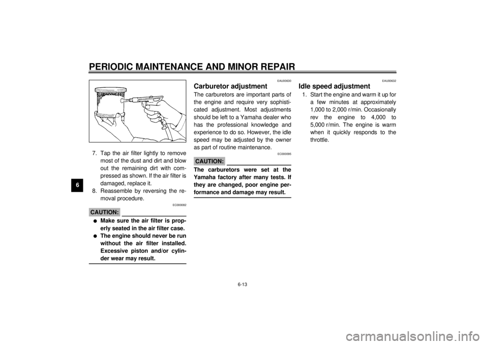
67. Tap the air filter lightly to remove
most of the dust and dirt and blow
out the remaining dirt with com-
pressed as shown. If the air filter is
damaged, replace it.
8. Reassemble by reversing the re-
moval procedure.
EC000082
CAUTION:@ l
Make sure the air filter is prop-
erly seated in the air filter case.
l
The engine should never be run
without the air filter installed.
Excessive piston and/or cylin-
der wear may result.
@
EAU00630
Carburetor adjustmentThe carburetors are important parts of
the engine and require very sophisti-
cated adjustment. Most adjustments
should be left to a Yamaha dealer who
has the professional knowledge and
experience to do so. However, the idle
speed may be adjusted by the owner
as part of routine maintenance.
EC000095
CAUTION:@ The carburetors were set at the
Yamaha factory after many tests. If
they are changed, poor engine per-
formance and damage may result. @
EAU00632
Idle speed adjustment1. Start the engine and warm it up for
a few minutes at approximately
1,000 to 2,000 r/min. Occasionally
rev the engine to 4,000 to
5,000 r/min. The engine is warm
when it quickly responds to the
throttle.
Page 63 of 97

PERIODIC MAINTENANCE AND MINOR REPAIR
6-17
6
EW000080
WARNING
@ l
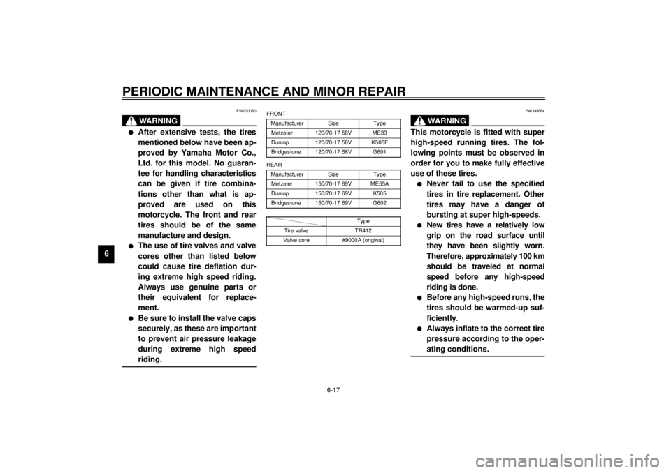
After extensive tests, the tires
mentioned below have been ap-
proved by Yamaha Motor Co.,
Ltd. for this model. No guaran-
tee for handling characteristics
can be given if tire combina-
tions other than what is ap-
proved are used on this
motorcycle. The front and rear
tires should be of the same
manufacture and design.
l
The use of tire valves and valve
cores other than listed below
could cause tire deflation dur-
ing extreme high speed riding.
Always use genuine parts or
their equivalent for replace-
ment.
l
Be sure to install the valve caps
securely, as these are important
to prevent air pressure leakage
during extreme high speed
riding.
@
CE-10E
CE-12EEAU00684
WARNING
@ This motorcycle is fitted with super
high-speed running tires. The fol-
lowing points must be observed in
order for you to make fully effective
use of these tires.l
Never fail to use the specified
tires in tire replacement. Other
tires may have a danger of
bursting at super high-speeds.
l
New tires have a relatively low
grip on the road surface until
they have been slightly worn.
Therefore, approximately 100 km
should be traveled at normal
speed before any high-speed
riding is done.
l
Before any high-speed runs, the
tires should be warmed-up suf-
ficiently.
l
Always inflate to the correct tire
pressure according to the oper-
ating conditions.
@
FRONT
Manufacturer Size Type
Metzeler 120/70-17 58V ME33
Dunlop 120/70-17 58V K505F
Bridgestone 120/70-17 58V G601
REAR
Manufacturer Size Type
Metzeler 150/70-17 69V ME55A
Dunlop 150/70-17 69V K505
Bridgestone 150/70-17 69V G602
Type
Tire valve TR412
Valve core #9000A (original)
Page 65 of 97
PERIODIC MAINTENANCE AND MINOR REPAIR
6-19
6
EAU00713
Brake light switch adjustmentThe rear brake light switch is activated
by the brake pedal and is properly ad-
justed when the brake light comes on
just before braking takes effect. To ad-
just the rear brake light switch, hold the
switch body so it does not rotate while
turning the adjusting nut.
Turn the adjusting nut in direction
a to
make the brake light come on earlier.
Turn the adjusting nut in direction
b to
make the brake light come on later.
EAU01160
Checking the front and rear
brake padsWear indicator grooves are provided
on each brake pad. These indicators
allow checking of brake pad wear with-
out disassembling the brake. Inspect
the grooves. If they have almost disap-
peared, ask a Yamaha dealer to re-
place the pads.
1. Brake light switch
2. Adjusting nut
1. Wear indicator groove (´ 6)
1. Wear indicator groove (´ 2)
Page 71 of 97

PERIODIC MAINTENANCE AND MINOR REPAIR
6-25
6Battery storage
When the motorcycle is not used for a
month or longer, remove the battery,
fully charge it and store it in a cool, dry
place.
EC000102
CAUTION:@ l
Completely recharge the bat-
tery before storing. Storing a
discharged battery can cause
permanent battery damage.
l
Use a battery charger designed
for a sealed-type (MF) battery.
Using a conventional battery
charger will cause battery dam-
age. If you do not have a sealed-
type battery charger, contact
your Yamaha dealer.
l
Always make sure the connec-
tions are correct when reinstall-
ing the battery.
@
EAU01110*
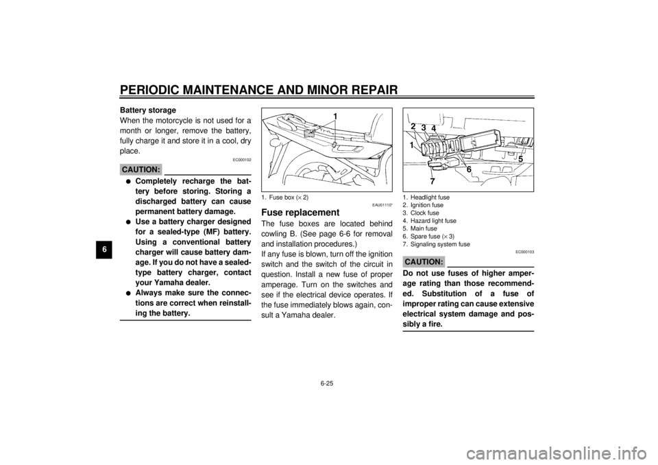
Fuse replacementThe fuse boxes are located behind
cowling B. (See page 6-6 for removal
and installation procedures.)
If any fuse is blown, turn off the ignition
switch and the switch of the circuit in
question. Install a new fuse of proper
amperage. Turn on the switches and
see if the electrical device operates. If
the fuse immediately blows again, con-
sult a Yamaha dealer.
EC000103
CAUTION:@ Do not use fuses of higher amper-
age rating than those recommend-
ed. Substitution of a fuse of
improper rating can cause extensive
electrical system damage and pos-
sibly a fire. @
1. Fuse box (´ 2)
1. Headlight fuse
2. Ignition fuse
3. Clock fuse
4. Hazard light fuse
5. Main fuse
6. Spare fuse (´ 3)
7. Signaling system fuse
Page 72 of 97
PERIODIC MAINTENANCE AND MINOR REPAIR
6-26
6
EAU00829
Headlight bulb replacementThis motorcycle is equipped with a
quartz bulb headlight.
If a headlight bulb burns out, replace it
as follows:
1. Remove the headlight connector
and the bulb holder cover.2. Unhook the bulb holder and re-
move the defective bulb.
EW000119
WARNING
@ Keep flammable products and your
hands away from a bulb while it is
on, as it is hot. Do not touch a bulb
until it cools down. @
Specified fuses:
Main fuse: 30 A
Headlight fuse: 15 A
Signaling system fuse: 20 A
Hazard light fuse: 10 A
Ignition fuse: 10 A
Clock fuse: 10 A
1. Connector
2. Bulb holder cover
1. Bulb holder