Page 29 of 97
INSTRUMENT AND CONTROL FUNCTIONS
3-15
3
EAU02925
SeatTo remove
Insert the key in the lock and turn it
counterclockwise.To install
Insert the projections on the front of the
seat into the seat holder, then push
down on the seat.
NOTE:@ Make sure that the seat is securely fit-
ted. @
EAU00263
Helmet holderThe helmet holder is under the seat.
Remove the seat and hook the helmet
on the helmet holder. Then, reinstall
the seat and lock it.
EW000030
WARNING
@ Never ride with a helmet in the hel-
met holder. The helmet may hit ob-
jects, causing loss of control and
possibly an accident. @
1. Seat lock
1. Projection (´ 2)
2. Seat holder
1. Helmet holder
Page 30 of 97
INSTRUMENT AND CONTROL FUNCTIONS
3-16
3
EAU01688
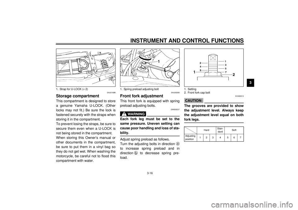
Storage compartmentThis compartment is designed to store
a genuine Yamaha U-LOCK. (Other
locks may not fit.) Be sure the lock is
fastened securely with the straps when
storing it in the compartment.
To prevent losing the straps, be sure to
secure them even when a U-LOCK is
not being stored in the compartment.
When storing this Owner’s manual or
other documents in the compartment,
be sure to put them in a vinyl bag so
they do not get wet. When washing the
motorcycle, be careful not to flood this
compartment with water.
EAU00285
Front fork adjustmentThis front fork is equipped with spring
preload adjusting bolts.
EW000037
WARNING
@ Each fork leg must be set to the
same pressure. Uneven setting can
cause poor handling and loss of sta-
bility. @Adjust spring preload as follows.
Turn the adjusting bolts in direction
a
to increase spring preload and in
direction
b to decrease spring pre-
load.
EC000013
CAUTION:@ The grooves are provided to show
the adjustment level. Always keep
the adjustment level equal on both
fork legs. @CI-18E
1. Strap for U-LOCK (´ 2)
1. Spring preload adjusting bolt
1. Setting
2. Front fork cap bolt
HardStan-
dardSoft
Adjusting
position123 4 567
Page 32 of 97
INSTRUMENT AND CONTROL FUNCTIONS
3-18
3
EAU00330
SidestandThis model is equipped with an ignition
circuit cut-off system. The motorcycle
must not be ridden when the sidestand
is down. The sidestand is located on
the left side of the frame. (Refer to
page 5-1 for an explanation of this sys-
tem.)
EW000044
WARNING
@ This motorcycle must not be operat-
ed with the sidestand in the down
position. If the stand is not properly
retracted, it could contact the
ground and distract the operator, re-
sulting in a possible loss of control.
Yamaha has designed into this
motorcycle a lockout system to as-
sist the operator in fulfilling the re-
sponsibility of retracting the
sidestand. Please check carefully
the operating instructions listed be-
low and if there is any indication of a
malfunction, return the motorcycle
to a Yamaha dealer immediately for
repair. @
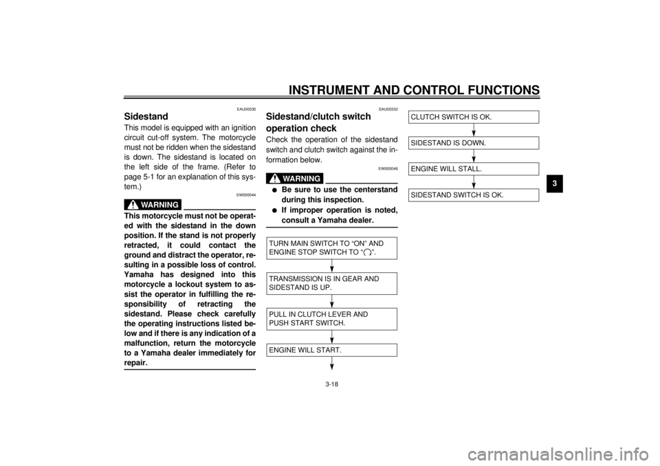
EAU00332
Sidestand/clutch switch
operation checkCheck the operation of the sidestand
switch and clutch switch against the in-
formation below.
EW000046
WARNING
@ l
Be sure to use the centerstand
during this inspection.
l
If improper operation is noted,
consult a Yamaha dealer.
@CD-08E
CD-08E
TURN MAIN SWITCH TO “ON” AND
ENGINE STOP SWITCH TO “ ”.TRANSMISSION IS IN GEAR AND
SIDESTAND IS UP.PULL IN CLUTCH LEVER AND
PUSH START SWITCH.ENGINE WILL START.
SIDESTAND IS DOWN.ENGINE WILL STALL.SIDESTAND SWITCH IS OK.CLUTCH SWITCH IS OK.
Page 64 of 97
PERIODIC MAINTENANCE AND MINOR REPAIR
6-18
6
EAU00687
WheelsTo ensure maximum performance,
long service, and safe operation, note
the following:l
Always inspect the wheels before
a ride. Check for cracks, bends, or
warpage of the wheels. If any ab-
normal condition exists in a wheel,
consult a Yamaha dealer. Do not
attempt even small repairs to the
wheel. If a wheel is deformed or
cracked, it must be replaced.
l
Tires and wheels should be bal-
anced whenever either one is
changed or replaced. Failure to
have a wheel balanced can result
in poor performance, adverse han-
dling characteristics, and short-
ened tire life.
l
Ride at moderate speeds after
changing a tire since the tire sur-
face must first be broken in for it to
develop its optimal characteristics.
EAU00694
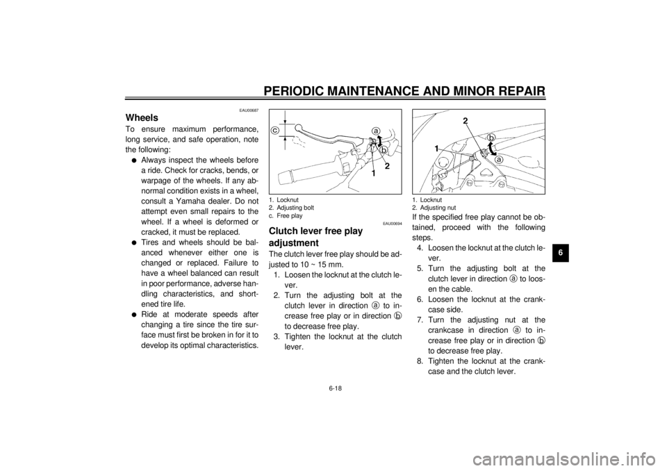
Clutch lever free play
adjustmentThe clutch lever free play should be ad-
justed to 10 ~ 15 mm.
1. Loosen the locknut at the clutch le-
ver.
2. Turn the adjusting bolt at the
clutch lever in direction
a to in-
crease free play or in direction
b
to decrease free play.
3. Tighten the locknut at the clutch
lever.If the specified free play cannot be ob-
tained, proceed with the following
steps.
4. Loosen the locknut at the clutch le-
ver.
5. Turn the adjusting bolt at the
clutch lever in direction
a to loos-
en the cable.
6. Loosen the locknut at the crank-
case side.
7. Turn the adjusting nut at the
crankcase in direction
a to in-
crease free play or in direction
b
to decrease free play.
8. Tighten the locknut at the crank-
case and the clutch lever.1. Locknut
2. Adjusting bolt
c. Free play
1. Locknut
2. Adjusting nut
Page 66 of 97
PERIODIC MAINTENANCE AND MINOR REPAIR
6-20
6
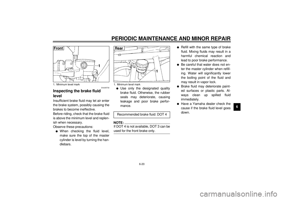
EAU00733
Inspecting the brake fluid
levelInsufficient brake fluid may let air enter
the brake system, possibly causing the
brakes to become ineffective.
Before riding, check that the brake fluid
is above the minimum level and replen-
ish when necessary.
Observe these precautions:l
When checking the fluid level,
make sure the top of the master
cylinder is level by turning the han-
dlebars.
l
Use only the designated quality
brake fluid. Otherwise, the rubber
seals may deteriorate, causing
leakage and poor brake perfor-
mance.
NOTE:@ If DOT 4 is not available, DOT 3 can be
used for the front brake only. @
l
Refill with the same type of brake
fluid. Mixing fluids may result in a
harmful chemical reaction and
lead to poor brake performance.
l
Be careful that water does not en-
ter the master cylinder when refill-
ing. Water will significantly lower
the boiling point of the fluid and
may result in vapor lock.
l
Brake fluid may deteriorate paint-
ed surfaces or plastic parts. Al-
ways clean up spilled fluid
immediately.
l
Have a Yamaha dealer check the
cause if the brake fluid level goes
down.
1. Minimum level mark
1. Minimum level markRecommended brake fluid: DOT 4
Page 71 of 97
PERIODIC MAINTENANCE AND MINOR REPAIR
6-25
6Battery storage
When the motorcycle is not used for a
month or longer, remove the battery,
fully charge it and store it in a cool, dry
place.
EC000102
CAUTION:@ l
Completely recharge the bat-
tery before storing. Storing a
discharged battery can cause
permanent battery damage.
l
Use a battery charger designed
for a sealed-type (MF) battery.
Using a conventional battery
charger will cause battery dam-
age. If you do not have a sealed-
type battery charger, contact
your Yamaha dealer.
l
Always make sure the connec-
tions are correct when reinstall-
ing the battery.
@
EAU01110*
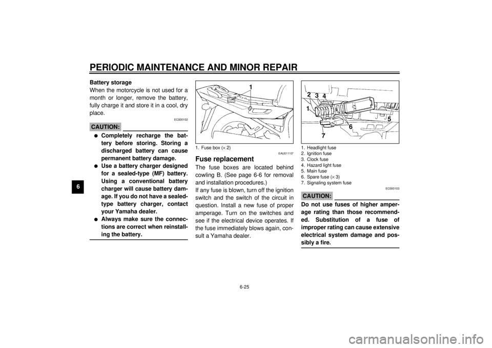
Fuse replacementThe fuse boxes are located behind
cowling B. (See page 6-6 for removal
and installation procedures.)
If any fuse is blown, turn off the ignition
switch and the switch of the circuit in
question. Install a new fuse of proper
amperage. Turn on the switches and
see if the electrical device operates. If
the fuse immediately blows again, con-
sult a Yamaha dealer.
EC000103
CAUTION:@ Do not use fuses of higher amper-
age rating than those recommend-
ed. Substitution of a fuse of
improper rating can cause extensive
electrical system damage and pos-
sibly a fire. @
1. Fuse box (´ 2)
1. Headlight fuse
2. Ignition fuse
3. Clock fuse
4. Hazard light fuse
5. Main fuse
6. Spare fuse (´ 3)
7. Signaling system fuse
Page 72 of 97
PERIODIC MAINTENANCE AND MINOR REPAIR
6-26
6
EAU00829
Headlight bulb replacementThis motorcycle is equipped with a
quartz bulb headlight.
If a headlight bulb burns out, replace it
as follows:
1. Remove the headlight connector
and the bulb holder cover.2. Unhook the bulb holder and re-
move the defective bulb.
EW000119
WARNING
@ Keep flammable products and your
hands away from a bulb while it is
on, as it is hot. Do not touch a bulb
until it cools down. @
Specified fuses:
Main fuse: 30 A
Headlight fuse: 15 A
Signaling system fuse: 20 A
Hazard light fuse: 10 A
Ignition fuse: 10 A
Clock fuse: 10 A
1. Connector
2. Bulb holder cover
1. Bulb holder
Page 90 of 97
SPECIFICATIONS
8-4
8
Headlight typeQuar tz bulb (halogen)
Bulb voltage, wattage ´ quantity
Headlight 12 V, 60/55 W ´ 1
Tail/brake light 12 V, 5/21 W ´ 2
Auxiliary light 12 V, 4 W ´ 1
Turn signal light 12 V, 21 W ´ 4
Meter light 12 V, 3.4 W ´ 4
Neutral indicator light 12 V, 3.4 W ´ 1
High beam indicator light 12 V, 3.4 W ´ 1
Oil level indicator light 12 V, 3.4 W ´ 1
Turn indicator light 12 V, 3.4 W ´ 2
Fuel indicator light 12 V, 3.4 W ´ 1
Fuses
Main fuse 30 A
Signaling system fuse 20 A
Headlight fuse 15 A
Hazard light fuse 10 A
Ignition fuse 10 A
Clock fuse 10 A