2000 YAMAHA TDR 125 oil temperature
[x] Cancel search: oil temperaturePage 15 of 104

INSTRUMENT AND CONTROL FUNCTIONS
Main switch/steering lock........................................3-1
Indicator lights ........................................................3-2
Oil level indicator circuit check ...............................3-3
Speedometer ..........................................................3-4
Tachometer ............................................................3-4
Engine temperature gauge .....................................3-5
Handlebar switches ................................................3-5
Headlight beam variation ........................................3-6
Clutch lever.............................................................3-8
Shift pedal...............................................................3-8
Front brake lever ....................................................3-8
Rear brake pedal ....................................................3-9
Fuel tank cap ..........................................................3-9
Fuel.......................................................................3-10
Catalyzer (for Switzerland and Austria) ................3-11
Two-stroke engine oil ...........................................3-12
Fuel cock ..............................................................3-12
Starter (choke) “1” ..............................................3-13
Seat ......................................................................3-13
Helmet holder .......................................................3-14
Rear shock absorber adjustment..........................3-14
Note on handling of the Yamaha Energy
Induction System (Y.E.I.S.) ..................................3-15Y.P.V.S. (Yamaha Power Valve System) .............3-16
Sidestand..............................................................3-16
Sidestand/clutch switch operation check ..............3-17
3
5AE-9-E3 (ENG) 4/11/0 11:06 AM Page 13
Page 55 of 104

6-10
1
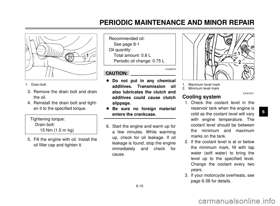
3. Remove the drain bolt and drain
the oil.
4. Reinstall the drain bolt and tight-
en it to the specified torque.
5. Fill the engine with oil. Install the
oil filler cap and tighten it.
EC000078
cC
8
8
Do not put in any chemical
additives. Transmission oil
also lubricates the clutch and
additives could cause clutch
slippage.
8 8
Be sure no foreign material
enters the crankcase.
6. Start the engine and warm up for
a few minutes. While warming
up, check for oil leakage. If oil
leakage is found, stop the engine
immediately and check for
cause.
1. Drain bolt
PERIODIC MAINTENANCE AND MINOR REPAIR
1
2
3
4
5
6
7
8
9 Tightening torque:
Drain bolt:
15 Nm (1.5 m0kg)
Recommended oil:
See page 8-1
Oil quantity:
Total amount: 0.8 L
Periodic oil change: 0.75 L
1
2
1. Maximum level mark
2. Minimum level mark
EAU01621*Cooling system
1. Check the coolant level in the
reservoir tank when the engine is
cold as the coolant level will vary
with engine temperature. The
coolant level should be between
the minimum and maximum
marks on the tank.
2. If the coolant level is at or below
the minimum mark, fill with tap
water (soft water) to bring the
level up to the specified level.
Change the coolant every two
years.
3. If your motorcycle overheats, see
page 6-38 for details.
5AE-9-E3 (ENG) 4/11/0 11:06 AM Page 53
Page 100 of 104

INDEX
Engine stop switch ..................................3-7
Engine temperature gauge ......................3-5
F
Front brake lever .....................................3-8
Front brake lever free play
adjustment ..........................................6-20
Front fork inspection ..............................6-28
Front wheel installation..........................6-34
Front wheel removal ..............................6-33
Fuel .......................................................3-10
Fuel cock ...............................................3-12
Fuel tank cap ...........................................3-9
Fuse replacement..................................6-30
H
Handlebar switches .................................3-5
Dimmer switch ......................................3-5
Engine stop switch ................................3-7
Headlight beam variation ......................3-6
Horn switch ...........................................3-5
Lights switch .........................................3-5
Start switch ...........................................3-7
Turn signal switch .................................3-5
Headlight beam variation.........................3-6
Headlight bulb replacement...................6-31
Helmet holder ........................................3-14
High beam indicator light .........................3-2
Horn switch..............................................3-5
How to use the conversion table .............8-5
I
Identification number records ..................9-1
Idle speed adjustment ...........................6-15
Indicator lights .........................................3-2
High beam indicator light ......................3-2Neutral indicator light ............................3-2
Oil level indicator light ...........................3-2
Turn indicator light ................................3-2
Inspecting the brake fluid level ..............6-22
K
Key identification number ........................9-1
L
Lights switch ............................................3-5
Left view ..................................................2-1
M
Main switch/Steering lock ........................3-1
Model lavel ..............................................9-2
N
Neutral indicator light...............................3-2
Note on handling of the Yamaha
Energy Induction System (Y.E.I.S.) ....3-15
O
Oil level indicator circuit check ................3-3
Oil level indicator light .............................3-2
P
Panel A ....................................................6-7
Parking ....................................................5-6
Periodic maintenance and
lubrication .............................................6-3
Pre-operation check list ...........................4-1
R
Rear brake pedal .....................................3-9
Rear brake pedal height adjustment .....6-20
Rear shock absorber adjustment ..........3-14
Rear suspension lubrication ..................6-27
Rear wheel installation ..........................6-35
Rear wheel removal ..............................6-34A
Air filter ..................................................6-13
Autolube pump adjustment....................6-26
B
Battery ...................................................6-29
Brake and clutch lever lubrication .........6-27
Brake and shift pedal lubrication ...........6-26
Brake fluid replacement.........................6-23
Brake light switch adjustment ................6-21
C
Cable inspection and lubrication ...........6-25
Carburetor adjustment...........................6-15
Care.........................................................7-1
Catalyzer
(for Switzerland and Austria) ..............3-11
Checking the front and rear brake
pads ....................................................6-21
Clutch lever .............................................3-8
Clutch lever free play adjustment ..........6-19
Controls/Instruments ...............................2-3
Cooling system ......................................6-11
Cowling A, B ............................................6-7
Cowling and panel removal and
installation .............................................6-6
D
Description ..............................................2-1
Dimmer switch .........................................3-5
Drive chain lubrication ...........................6-25
Drive chain slack adjustment.................6-24
Drive chain slack check .........................6-23
E
Engine break-in .......................................5-5
5AE-9-E3 (ENG) 4/11/0 11:06 AM Page 98