2000 YAMAHA TDM 850 light
[x] Cancel search: lightPage 42 of 99
OPERATION AND IMPORTANT RIDING POINTS
5-4
5
EAU01258
Starting a warm engineThe starter (choke) is not required
when the engine is warm.
EC000046
CAUTION:@ See the “Engine break-in” section
prior to operating the motorcycle for
the first time. @
EAU00423
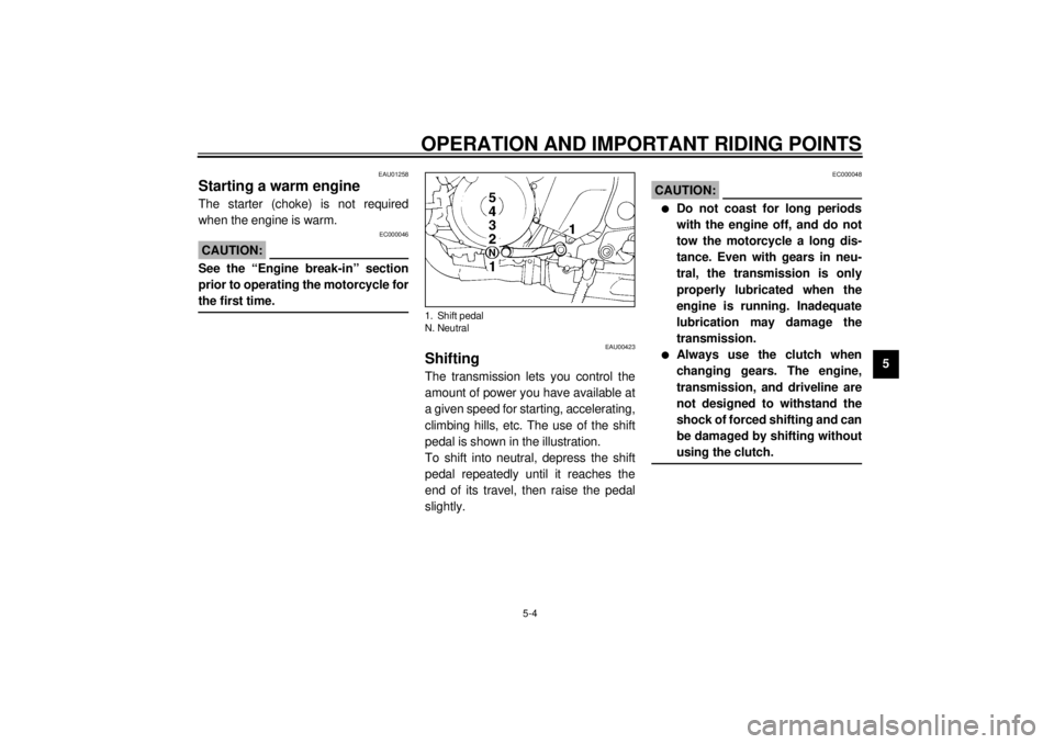
ShiftingThe transmission lets you control the
amount of power you have available at
a given speed for starting, accelerating,
climbing hills, etc. The use of the shift
pedal is shown in the illustration.
To shift into neutral, depress the shift
pedal repeatedly until it reaches the
end of its travel, then raise the pedal
slightly.
EC000048
CAUTION:@ l
Do not coast for long periods
with the engine off, and do not
tow the motorcycle a long dis-
tance. Even with gears in neu-
tral, the transmission is only
properly lubricated when the
engine is running. Inadequate
lubrication may damage the
transmission.
l
Always use the clutch when
changing gears. The engine,
transmission, and driveline are
not designed to withstand the
shock of forced shifting and can
be damaged by shifting without
using the clutch.
@
1. Shift pedal
N. Neutral
E_4tx_Operation.fm Page 4 Saturday, October 16, 1999 9:37 AM
Page 43 of 99

OPERATION AND IMPORTANT RIDING POINTS
5-5
5
EAU00424
Tips for reducing fuel
consumptionYour motorcycle’s fuel consumption
depends to a large extent on your
riding style. The following tips can help
reduce fuel consumption:l
Warm up the engine before riding.
l
Turn off the starter (choke) as
soon as possible.
l
Shift up swiftly and avoid high en-
gine speeds during acceleration.
l
Do not double-clutch or rev the en-
gine while shifting down and avoid
high engine speeds with no load
on the engine.
l
Turn off the engine instead of let-
ting it idle for an extended length
of time, i.e. in traffic jams, at traffic
lights or railroad crossings.
EAU00436
Engine break-inThere is never a more important period
in the life of your motorcycle than the
period between zero and 1,000 km. For
this reason we ask that you carefully
read the following material. Because
the engine is brand new, you must not
put an excessive load on it for the first
1,000 km. The various parts in the en-
gine wear and polish themselves to the
correct operating clearances. During
this period, prolonged full throttle oper-
ation, or any condition which might re-
sult in excessive heating of the engine,
must be avoided.
EAU00440
0 ~ 150 km
Avoid operation above 5,000 r/min.
Stop the engine and let it cool for 5 to
10 minutes after every hour of opera-
tion. Vary the speed of the motorcycle
from time to time. Do not operate it at
one set throttle position.
150 ~ 500 km
Avoid prolonged operation above
6,000 r/min. Rev the motorcycle freely
through the gears, but do not use full
throttle at any time.
500 ~ 1,000 km
Avoid prolonged full throttle operation.
Avoid cruising speeds in excess of
7,000 r/min.
EC000052
CAUTION:@ After 1,000 km of operation, be sure
to replace the engine oil and oil fil-
ter. @
E_4tx_Operation.fm Page 5 Saturday, October 16, 1999 9:37 AM
Page 46 of 99

6
PERIODIC MAINTENANCE AND MINOR REPAIR
Tool kit................................................................... 6-1
Periodic maintenance and lubrication ................... 6-2
Cowling and panel removal and installation.......... 6-5
Cowlings A and B ................................................. 6-5
Panels A and B ..................................................... 6-6
Spark plugs........................................................... 6-6
Engine oil .............................................................. 6-8
Cooling system ................................................... 6-10
Changing the coolant .......................................... 6-11
Air filter ............................................................... 6-13
Carburetor adjustment ........................................ 6-15
Idle speed adjustment ........................................ 6-15
Throttle cable free play inspection ...................... 6-16
Valve clearance adjustment ................................ 6-16
Tires .................................................................... 6-17
Clutch lever free play adjustment........................ 6-19
Rear brake pedal height adjustment ................... 6-20
Brake light switch adjustment ............................. 6-21
Checking the front and rear brake pads.............. 6-21
Inspecting the brake fluid level............................ 6-22
Brake fluid replacement ...................................... 6-23Drive chain slack check ...................................... 6-23
Drive chain slack adjustment ............................. 6-23
Drive chain lubrication........................................ 6-24
Cable inspection and lubrication ........................ 6-24
Throttle cable and grip lubrication ...................... 6-25
Brake and shift pedal lubrication ........................ 6-25
Brake and clutch lever lubrication ...................... 6-25
Sidestand lubrication.......................................... 6-26
Rear suspension lubrication............................... 6-26
Front fork inspection ........................................... 6-27
Steering inspection ............................................ 6-27
Wheel bearings .................................................. 6-28
Battery................................................................ 6-28
Fuse replacement .............................................. 6-29
Headlight bulb replacement ............................... 6-30
Tail/brake light bulb replacement ........................ 6-31
Turn signal light bulb replacement...................... 6-32
Troubleshooting .................................................. 6-32
Troubleshooting chart ......................................... 6-33
Engine overheating ............................................ 6-34
E_4tx_PeriodicTOC.fm Page 1 Saturday, October 16, 1999 9:37 AM
Page 52 of 99
PERIODIC MAINTENANCE AND MINOR REPAIR
6-6
6
EAU01691*
Panels A and BTo remove
1. Remove the seat. (See page 3-12
for removal and installation proce-
dures.)
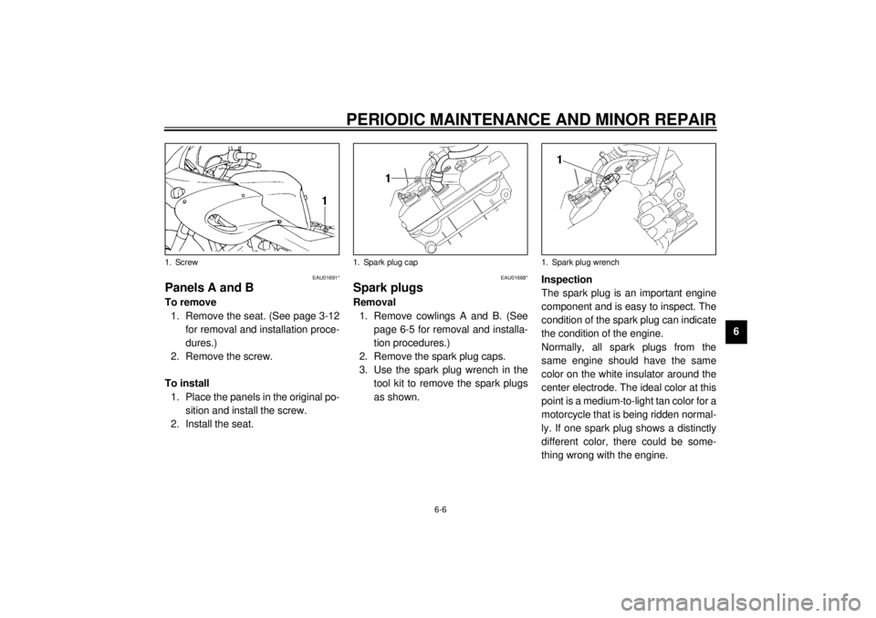
2. Remove the screw.
To install
1. Place the panels in the original po-
sition and install the screw.
2. Install the seat.
EAU01668*
Spark plugsRemoval
1. Remove cowlings A and B. (See
page 6-5 for removal and installa-
tion procedures.)
2. Remove the spark plug caps.
3. Use the spark plug wrench in the
tool kit to remove the spark plugs
as shown.Inspection
The spark plug is an important engine
component and is easy to inspect. The
condition of the spark plug can indicate
the condition of the engine.
Normally, all spark plugs from the
same engine should have the same
color on the white insulator around the
center electrode. The ideal color at this
point is a medium-to-light tan color for a
motorcycle that is being ridden normal-
ly. If one spark plug shows a distinctly
different color, there could be some-
thing wrong with the engine.
1. Screw
1. Spark plug cap
1. Spark plug wrench
E_4tx_Periodic.fm Page 6 Saturday, October 16, 1999 9:37 AM
Page 54 of 99

PERIODIC MAINTENANCE AND MINOR REPAIR
6-8
6
EAU01692
Engine oilOil level inspection
1. Place the motorcycle on a level
place. Warm up the engine at idle
for 15 minutes.NOTE:@ Be sure the motorcycle is positioned
straight up when checking the oil level.
A slight tilt toward the side can result in
false readings. @
2. The oil tank is located behind the
engine cylinders. With the engine
stopped, check the oil level
through the level window located
on the right side of the oil tank.
3. The oil level should be between
the maximum and minimum
marks. If the level is low, fill engine
with sufficient oil to raise it to the
specified level.Engine oil and oil filter element re-
placement
1. Warm up the engine for a few min-
utes.
2. Stop the engine. Place an oil pan
under the engine and remove the
oil filler cap.
3. Remove the drain bolts and drain
the oil.
4. Remove the oil filter cover bolts
and oil filter.
1. Oil level window
2. Minimum level mark
3. Maximum level mark
1. Engine oil filler cap
1. Engine oil drain bolt a
E_4tx_Periodic.fm Page 8 Saturday, October 16, 1999 9:37 AM
Page 59 of 99
PERIODIC MAINTENANCE AND MINOR REPAIR
6-13
6
EAU01769*
Air filterThe air filter should be cleaned at the
specified intervals. It should be cleaned
more frequently if you are riding in un-
usually wet or dusty areas.
1. Remove the seat. (See page 3-12
for seat removal and installation
procedures.)
2. Remove cowlings A and B and
panels A and B. (See pages 6-5
~
6-6 for removal and installation
procedures.)
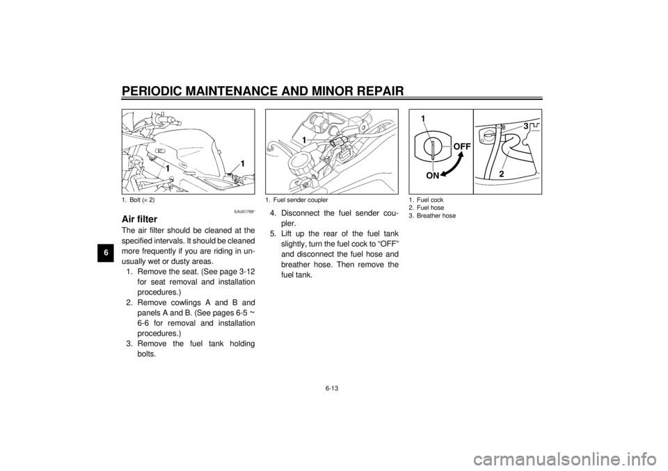
3. Remove the fuel tank holding
bolts.4. Disconnect the fuel sender cou-
pler.
5. Lift up the rear of the fuel tank
slightly, turn the fuel cock to “OFF”
and disconnect the fuel hose and
breather hose. Then remove the
fuel tank.
1. Bolt (´ 2)
1. Fuel sender coupler
1. Fuel cock
2. Fuel hose
3. Breather hose
E_4tx_Periodic.fm Page 13 Saturday, October 16, 1999 9:37 AM
Page 60 of 99
PERIODIC MAINTENANCE AND MINOR REPAIR
6-14
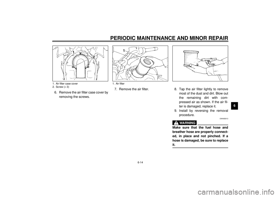
6 6. Remove the air filter case cover by
removing the screws.7. Remove the air filter. 8. Tap the air filter lightly to remove
most of the dust and dirt. Blow out
the remaining dirt with com-
pressed air as shown. If the air fil-
ter is damaged, replace it.
9. Install by reversing the removal
procedure.
EWA00013
WARNING
@ Make sure that the fuel hose and
breather hose are properly connect-
ed, in place and not pinched. If a
hose is damaged, be sure to replace
it. @
1. Air filter case cover
2. Screw (´ 3)
1. Air filter
E_4tx_Periodic.fm Page 14 Saturday, October 16, 1999 9:37 AM
Page 65 of 99
PERIODIC MAINTENANCE AND MINOR REPAIR
6-19
6
CE-10E
CE-12EEAU00684
WARNING
@ This motorcycle is fitted with super
high-speed running tires. The fol-
lowing points must be observed in
order for you to make fully effective
use of these tires.l
Never fail to use the specified
tires in tire replacement. Other
tires may have a danger of
bursting at super high-speeds.
l
New tires have a relatively low
grip on the road surface until
they have been slightly worn.
Therefore, approximately 100 km
should be traveled at normal
speed before any high-speed
riding is done.
l
Before any high-speed runs, the
tires should be warmed-up suf-
ficiently.
l
Always inflate to the correct tire
pressure according to the oper-
ating conditions.
@
EAU00692
Clutch lever free play
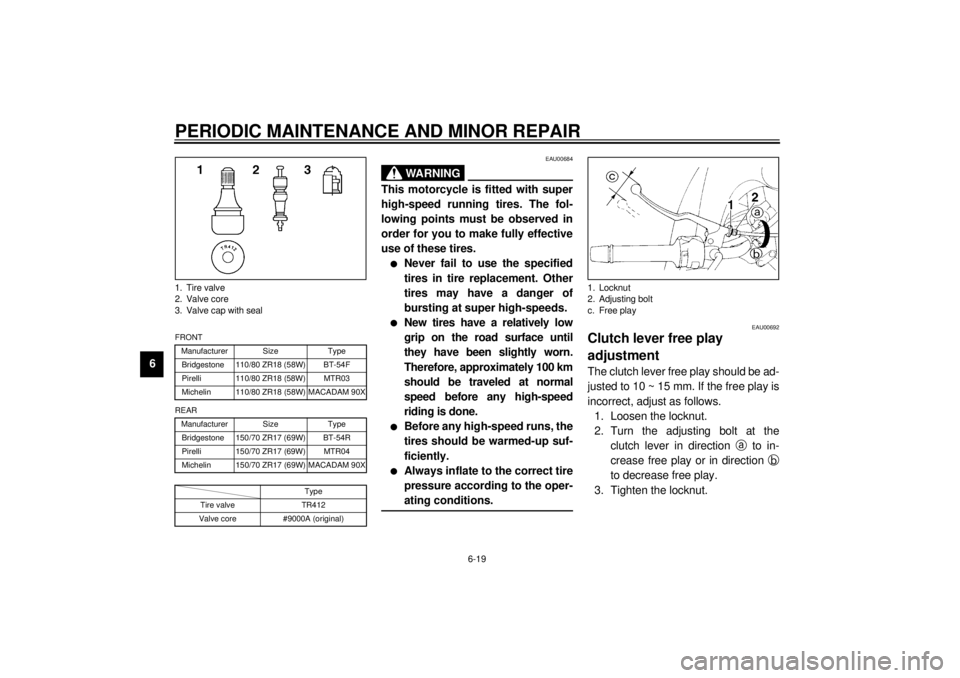
adjustmentThe clutch lever free play should be ad-
justed to 10 ~ 15 mm. If the free play is
incorrect, adjust as follows.
1. Loosen the locknut.
2. Turn the adjusting bolt at the
clutch lever in direction
a to in-
crease free play or in direction
b
to decrease free play.
3. Tighten the locknut.
1. Tire valve
2. Valve core
3. Valve cap with sealFRONT
Manufacturer Size Type
Bridgestone 110/80 ZR18 (58W) BT-54F
Pirelli 110/80 ZR18 (58W) MTR03
Michelin 110/80 ZR18 (58W) MACADAM 90X
REAR
Manufacturer Size Type
Bridgestone 150/70 ZR17 (69W) BT-54R
Pirelli 150/70 ZR17 (69W) MTR04
Michelin 150/70 ZR17 (69W) MACADAM 90X
Type
Tire valve TR412
Valve core #9000A (original)
1. Locknut
2. Adjusting bolt
c. Free play
E_4tx_Periodic.fm Page 19 Saturday, October 16, 1999 9:37 AM