Page 216 of 256

Celica_U
2152000 CELICA (OM20735U)
If the level is low, add SAE J1703 or
FMVSS No.116 DOT 3 brake fluid to the
brake reservoir.
Remove and replace the reservoir cap by
hand. Fill the brake fluid to the dotted
line. This brings the fluid to the correct
level when you put the cap back on.
Use only newly opened brake fluid. Once
opened, brake fluid absorbs moisture from
the air, and excess moisture can cause a
dangerous loss of braking.
CAUTION
Take care when filling the reservoir
because brake fluid can harm your
eyes and damage painted surfaces. If
fluid gets in your eyes, flush your
eyes with clean water.
NOTICE
If you spill the fluid, be sure to wash
it off with water to prevent it from
damaging the parts or paint.
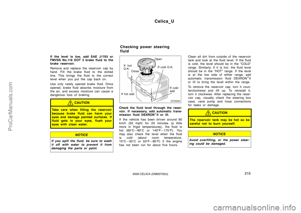
If hot
O.K.Close Open
If hot add If cold
add
If cold O.K.
Check the fluid level through the reser-
voir. If necessary, add automatic trans-
mission fluid DEXRON
�II or III.
If the vehicle has been driven around 80
km/h (50 mph) for 20 minutes (a little
more in frigid temperatures), the fluid is
hot (60 °C—80 °C or 140 °F—175 °F). You
may also check the level when the fluid
is cold (about room temperature,
10 °C—30 °C or 50 °F—85 °F) if the engine
has not been run for about five hours. Clean all dirt from outside of the reservoir
tank and look at the fluid level. If the fluid
is cold, the level should be in the “COLD”
range. Similarly, if it is hot, the fluid level
should be in the “HOT” range. If the level
is at the low side of either range, add
automatic transmission fluid DEXRON
�II
or III to bring the level within the range.
To remove the reservoir cap, turn it coun-
terclockwise and lift up. To reinstall it,
turn it clockwise. After replacing the reser-
voir cap, visually check the steering box
case, vane pump and hose connections
for leaks or damage.
CAUTION
The reservoir tank may be hot so be
careful not to burn yourself.
NOTICE
Avoid overfilling, or the power steer-
ing could be damaged.
Checking power steering
fluid
ProCarManuals.com
Page 236 of 256
Celica_U
2352000 CELICA (OM20735U)
2. Unplug the connector. Remove therubber cover.
If the connector is tight, wiggle it.3. Release the bulb retaining spring and remove the bulb along with the
socket. Install a new bulb into the
socket and return the bulb retaining
spring to its original position.
To install a bulb, align the tabs of the
bulb with the cutout of the mounting hole.4. Install the rubber cover with the “TOP” mark upward, and snuggle on
the boss. Insert the connector.
Make sure the rubber cover fits snugly on
the connector and the headlight body.
Aiming is not necessary after replacing
the bulb. When aiming adjustment is nec-
essary, contact your Toyota dealer.
ProCarManuals.com
Page 250 of 256

Celica_U
2492000 CELICA (OM20735U)
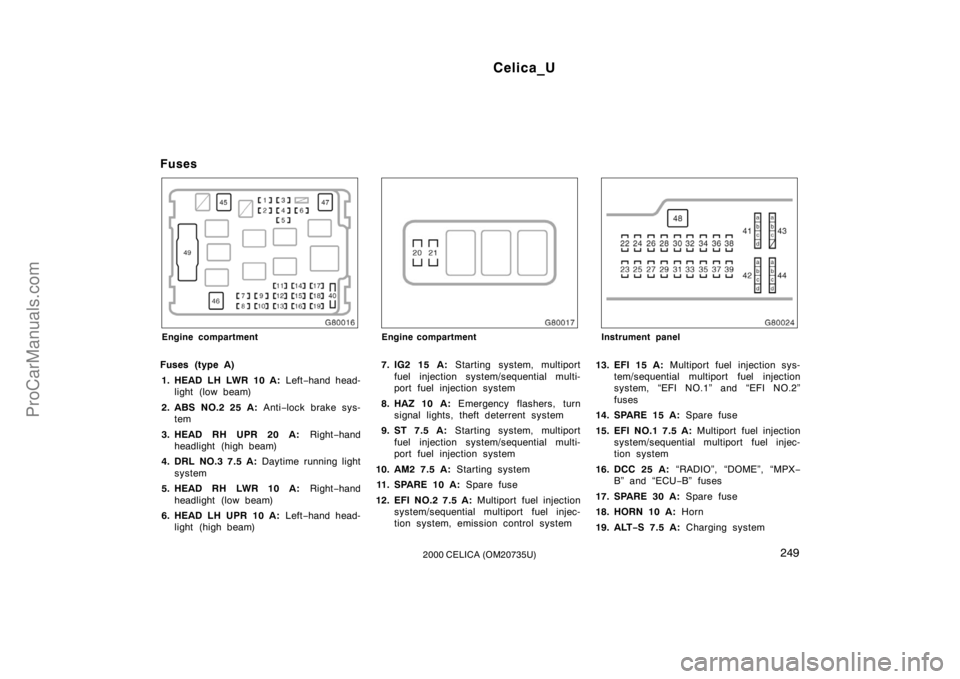
Fuses
Engine compartment
Fuses (type A)1. HEAD LH LWR 10 A: Left−hand head-
light (low beam)
2. ABS NO.2 25 A: Anti−lock brake sys-
tem
3. HEAD RH UPR 20 A: Right−hand
headlight (high beam)
4. DRL NO.3 7.5 A: Daytime running light
system
5. HEAD RH LWR 10 A: Right−hand
headlight (low beam)
6. HEAD LH UPR 10 A: Left−hand head-
light (high beam)
Engine compartment
7. IG2 15 A: Starting system, multiport
fuel injection system/sequential multi-
port fuel injection system
8. HAZ 10 A: Emergency flashers, turn
signal lights, theft deterrent system
9. ST 7.5 A: Starting system, multiport
fuel injection system/sequential multi-
port fuel injection system
10. AM2 7.5 A: Starting system
11. SPARE 10 A: Spare fuse
12. EFI NO.2 7.5 A: Multiport fuel injection
system/se quential multiport fuel injec-
tion system, emission control system
Instrument panel
13. EFI 15 A: Multiport fuel injection sys-
tem/sequential multiport fuel injection
system, “EFI NO.1” and “EFI NO.2”
fuses
14. SPARE 15 A: Spare fuse
15. EFI NO.1 7.5 A: Multiport fuel injection
system/s equential multiport fuel injec-
tion system
16. DCC 25 A: “RADIO”, “DOME”, “MPX −
B” and “ECU −B” fuses
17. SPARE 30 A: Spare fuse
18. HORN 10 A: Horn
19. ALT− S 7.5 A: Charging system
ProCarManuals.com
Page 251 of 256

Celica_U
2502000 CELICA (OM20735U)
20. HEAD RH UPR 10 A: Right−hand
headlight (high beam), daytime running
light system
21. HEAD LH UPR 10 A: Left−hand head-
light (high beam)
22. S/ROOF 15 A: Electric moon roof
23. CIG 15 A: Cigarette lighter
24. FL P/W 20 A: Power windows
25. AM1 25 A: Starting system, “CIG”,
“ECU ACC”, “SRS −IG”, “WASHER”,
“WIPER”, “BK/UP LP”, “TENS RDC”,
“DEF RLY”, “BODY ECU −IG”, “TURN”,
“HTR”, “WARNING”, “FAN RLY”, “ABS −
IG” and “ECU −IG” fuses
26. STOP 10 A: Stop lights, anti −lock
brake system, high mounted stoplight,
multiport fuel injection system/sequen-
tial multiport fuel injection system, elec-
tronically controlled automatic transmis-
sion system, cruise control system
27. DOOR 20 A: Power door lock system
28. SRS −IG 7.5 A: SRS airbag system
29. FR FOG 15 A: Front fog lights
30. WASHER 15 A: Windshield wipers and
washer, rear window wiper and washer
31. OBD 7.5 A: On−board diagnosis sys-
tem 32. RADIO 15 A:
Car audio system
33. WIPER 25 A: Windshield wipers and
washer
34. TURN 7.5 A: Turn signal lights
35. MIR HTR 10 A: No circuit
36. HTR 10 A: Air conditioning system
37. RR WIPER 15 A: Rear window wiper
and washer
38. TAIL 10 A: Tail lights, instrument panel
lights, license plate lights, front side
maker lights
39. FR P/W 20 A: Power windows
Fuses (type B)
40. SPARE 7.5 A: Spare fuse
41. a. MPX −B 7.5 A: Wireless remote con-
trol system
b. RR FOG 7.5 A: No circuit
c. DOME 7.5 A: Clock, interior lights
d. ECU −B 7.5 A: Air conditioning sys-
tem, gauges and meters
42. a. WARNING 5 A: Charging system,
gauges and meters
b. ECU −IG 5 A: Cruise control system
c. ABS −IG 5 A: Anti−lo
ck brake sys-
tem
d. FAN RLY 5 A: Electric cooling
fans 43. a. PANEL1 7.5 A:
Gauges and meters,
air conditioning system, electronical-
ly controlled automatic transmission
system, headlight beam level control
system, front fog lights, emer gency
flasher, turn signal lights
b. PANEL2 7.5 A: Car audio system,
cigarette lighter, glove box light
c. ECU −ACC 7.5 A: Clock, car audio
system, power rear view mirror con-
trols
44. a. BK/UP LP 5 A: Back−up lights
b. DEF RLY 5 A: Power windows, rear
window defogger
c. BODY ECU −IG 5 A: Theft deterrent
system
d. TENS RDC 5 A: Electronically con-
trolled automatic transmission sys-
tem, shift lock control system, elec-
tric moon roof
Fuses (type C)
45. ABS NO.1 40 A: Anti−lock brake sys-
tem
46. MAIN 40 A: Starting system, daytime
running light system
47. HTR 50 A: Air conditioning system
48. DEF 30 A: Rear window defogger
ProCarManuals.com
Page 252 of 256
Celica_U
2512000 CELICA (OM20735U)
Fuses (type D)
49. ALT 120 A: Cooling system, electric
cooling fans, starting system, rear win-
dow defogger, tail lights, “ABS NO.1”,
“ABS NO.2”, “HTR”, “FR P/W”, “FL
P/W”, “DOOR”, “OBD”, “STOP”, “S/
ROOF”, “MIR HTR”, “FR FOG” and
“AM1” fuses
ProCarManuals.com