Page 2504 of 4770

319 Author�: Date�:
DTC P0171 System too Lean (Fuel Trim)
(Except California Spec.)
DTC P0172 System too Rich (Fuel Trim)
(Except California Spec.)
CIRCUIT DESCRIP")
DI±84
± DIAGNOSTICSENGINE (5S±FE)
319 Author�: Date�:
DTC P0171 System too Lean (Fuel Trim)
(Except California Spec.)
DTC P0172 System too Rich (Fuel Trim)
(Except California Spec.)
CIRCUIT DESCRIPTION
Fuel trim refers to the feedback compensation value compared against the basic injection time. Fuel trim
includes short±term fuel trim and long±term fuel trim.
Short±term fuel trim is the short±term fuel compensation used to maintain the air±fuel ratio at its ideal
theoretical value. The signal from the heated oxygen sensor indicates whether the air±fuel ratio is RICH or
LEAN compared to the ideal theoretical value, triggering a reduction in fuel volume if the air±fuel ratio is rich,
and an increase in fuel volume if it is lean.
Long±term fuel trim is overall fuel compensation carried out long±term to compensate for continual deviation
of the short±term fuel trim from the central value due to individual engine differences, wear over time and
changes in the usage environment.
If both the short±term fuel trim and long±term fuel trim are LEAN or RICH beyond a certain value, it is
detected as a malfunction and the MIL lights up.
DTC No.DTC Detecting ConditionTrouble Area
P0171
When air±fuel ratio feedback is stable after engine warming up,
fuel trim is considerably in error on RICH side
(2 trip detection logic)
�Gas leakage on exhaust system
�Air intake (hose loose)
�Fuel line pressure
�Injector blockage
�Heated oxygen sensor (bank 1 sensor 1)
�Manifold absolute pressure sensor
�Engine coolant temp. sensor
P0172
When air±fuel ratio feedback is stable after engine warming up,
fuel trim is considerably in error on LEAN side
(2 trip detection logic)
�Gas leakage on exhaust system
�Fuel line pressure
�Injector leak, blockage
�Heated oxygen sensor (bank 1 sensor 1)
�Manifold absolute pressure sensor
�Engine coolant temp. sensor
HINT:
�When the DTC P0171 is recorded, the actual air±fuel ratio is on the LEAN side. When DTC P0172 is
recorded, the actual air±fuel ratio is on the RICH side.
�If the vehicle runs out of fuel, the air±fuel ratio is LEAN and DTC P0171 is recorded. The MIL then
comes on.
�If the total of the short±term fuel trim value and long±term fuel trim value is within + 38 %, the system
is functioning normally.
�The heated oxygen sensor (bank 1 sensor 1) output voltage and the short±term fuel trim value can
be read using the OBD II scan tool or TOYOTA hand±held tester.
DI4NG±01
Page 2505 of 4770
± DIAGNOSTICSENGINE (5S±FE)
DI±85
320 Author�: Date�:
INSPECTION PROCEDURE
HINT:
Read freeze frame data using TOYOTA hand±held tester or OBD II scan tool. Because freeze frame records
the engine conditions when the malfunction is detected, when troubleshooting it is useful for determining
whether the vehicle was running or stopped, the engine warmed up or not, the air±fuel ratio lean or rich, etc.
at the time of the malfunction.
1 Check air induction system (See page SF±1).
NG Repair or replace.
OK
2 Check injector injection (See page SF±23).
NG Replace injector.
OK
3 Check manifold absolute pressure sensor and engine coolant temp. sensor
(See pages SF±53 and SF±49).
NG Repair or replace.
OK
4 Check for spark and ignition (See page IG±1).
NG Repair or replace.
OK
Page 2507 of 4770
P18349
± DIAGNOSTICSENGINE (5S±FE)
DI±87
322 Author�: Date�:
7 Check the output voltage of heated oxygen sensor during idling.
PREPARATION:
Warm up the heated oxygen sensor the engine at 2,500 rpm for approx. 90 sec.
CHECK:
Use the OBD II scan tool or TOYOTA hand±held tester to read the output voltage of the heated oxygen sen-
sor during idling.
OK:
Heated oxygen sensor output voltage:
Alternates repeatedly between less than 0.4 V and more than 0.55 V (See the following table).
OK Go to step 9.
NG
8 Check for open and short in harness and connector between ECM and oxygen
sensor (See page IN±31).
NG Repair or replace harness or connector.
OK
Replace oxygen sensor.
Page 2509 of 4770

DI±89
324 Author�: Date�:
DTC P0300 Random/Multiple Cylinder Misfire Detected
DTC P0301 Cylinder 1 Misfire Detected
DTC P0302 Cylinder 2 Misfire Detected
DTC P0303 Cylin")
± DIAGNOSTICSENGINE (5S±FE)
DI±89
324 Author�: Date�:
DTC P0300 Random/Multiple Cylinder Misfire Detected
DTC P0301 Cylinder 1 Misfire Detected
DTC P0302 Cylinder 2 Misfire Detected
DTC P0303 Cylinder 3 Misfire Detected
DTC P0304 Cylinder 4 Misfire Detected
CIRCUIT DESCRIPTION
Misfire: The ECM uses the crankshaft position sensor and camshaft position sensor to monitor changes in
the crankshaft rotation for each cylinder.
The ECM counts the number of times the engine speed change rate indicates that misfire has occurred. And
when the misfire rate equals or exceeds the count indicating that the engine condition has deteriorated, the
MIL lights up.
If the misfire rate is high enough and the driving conditions will cause catalyst overheating, the MIL blinks
when misfiring occurs.
DTC No.DTC Detecting ConditionTrouble Area
P0300Mi fi i f d li d i d t t d d i ti l
�Ignition system
�Injector
�Fuel line pressure
�EGR
P0300
P0301
P0302
P0303
P0304
Misfiring of random cylinders is detected during any particular
200 or 1,000 revolutions
For any particular 200 revolutions for engine, misfiring is de-
tected which can cause catalyst overheating
(This causes MIL to blink)
�EGR
�Compression pressure
�Valve clearance not to specification
�Valve timing
�Manifold absolute pressure sensor
P0304(This causes MIL to blink)�Manifold absolute ressure sensor
�Engine coolant temp. sensor
�Open or short in engine wire
�Connector connection
�ECM
HINT:
When the 2 or more codes for a misfiring cylinder are recorded repeatedly but no random misfire code is
recorded, it indicates that the misfires were detected and recorded at different times.
DI011±07
Page 2516 of 4770
DI±96
± DIAGNOSTICSENGINE (5S±FE)
331 Author�: Date�:
8 Check manifold absolute pressure sensor and engine coolant temp. sensor
(See pages SF±53 AND SF±49).
NG Repair or replace.
OK
Check compression pressure, valve
clearance and valve timing
(See pages EM±3, EM±4 AND EM±23).
Page 2517 of 4770
 (*2)
E812
± DIAGNOSTICSENGINE (5S±FE)
DI±97
332 Author�: Date�:
DTC P0325 Knock Sensor 1 Circuit Malfunction
CI")
A03598
Knock Sensor 1ECM
KNK
E1 E8 13
W 1
*1: w/o Immobiliser
*2: w/ Immobiliser
(*1) (*2)
E812
± DIAGNOSTICSENGINE (5S±FE)
DI±97
332 Author�: Date�:
DTC P0325 Knock Sensor 1 Circuit Malfunction
CIRCUIT DESCRIPTION
The knock sensor is fitted to the cylinder block to detect engine knocking. This sensor contains a piezoelec-
tric element which generates a voltage when it becomes deformed, which occurs when the cylinder block
vibrates due to knocking. If engine knocking occurs, ignition timing is retarded to suppress it.
DTC No.DTC Detecting ConditionTrouble Area
P0325
No knock sensor 1 signal to ECM with engine speed, 1,200
rpm or more
(2 trip detection logic)�Open or short in knock sensor 1 circuit
�Knock sensor 1 (looseness)
�ECM
HINT:
If the ECM detects above diagnosis conditions, it operates the fail safe function in which the corrective retard
angle value is set to the maximum value.
WIRING DIAGRAM
INSPECTION PROCEDURE
HINT:
Read freeze frame data using TOYOTA hand±held tester or OBD II scan tool. Because freeze frame records
the engine conditions when the malfunction is detected, when troubleshooting it is useful for determining
whether the vehicle was running or stopped, the engine warmed up or not, the air±fuel ratio lean or rich, etc.
at the time of the malfunction.
DI012±10
Page 2518 of 4770
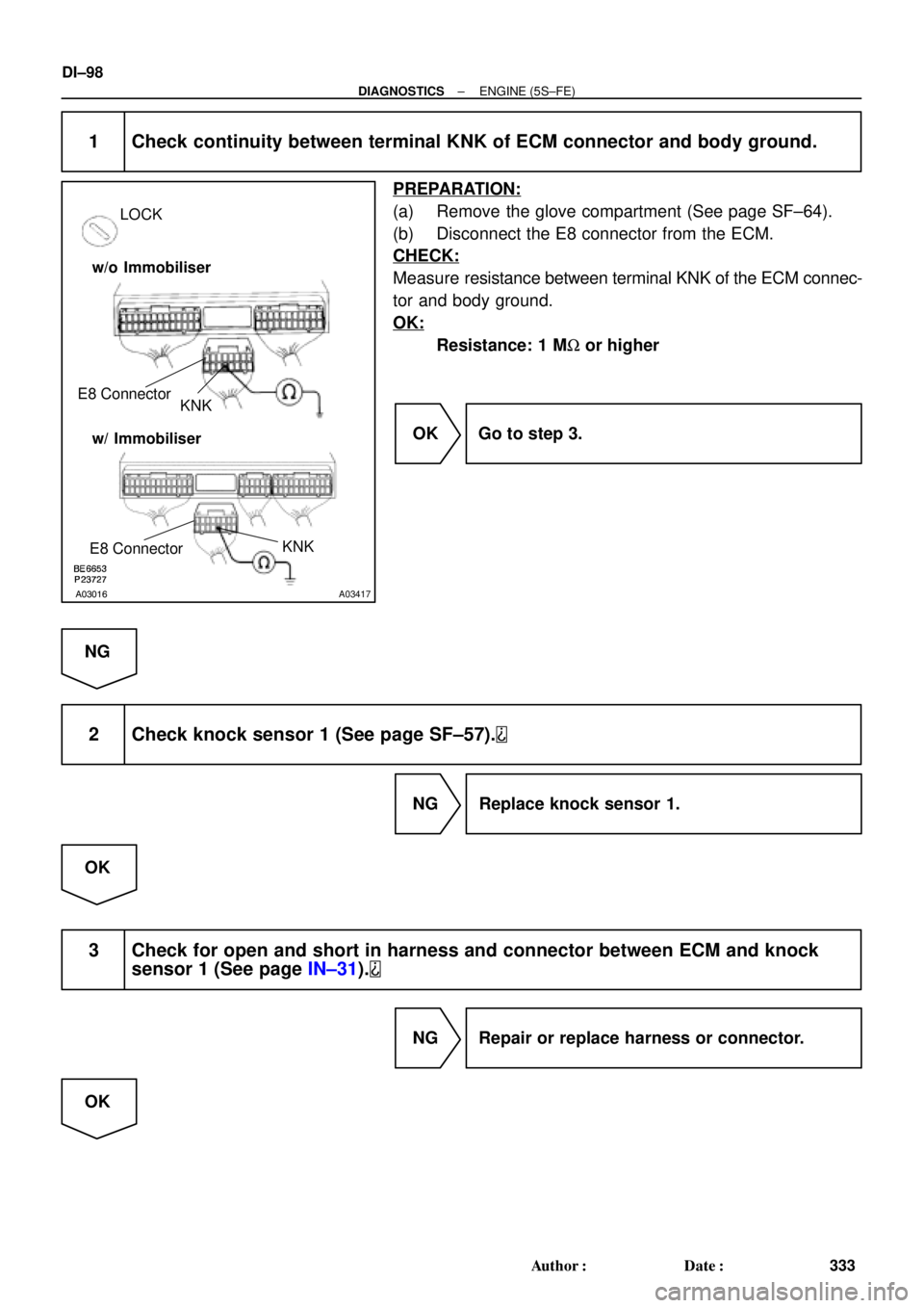
A03016A03417
LOCK
KNK E8 Connector
w/o Immobiliser
w/ Immobiliser
KNK
E8 Connector
DI±98
± DIAGNOSTICSENGINE (5S±FE)
333 Author�: Date�:
1 Check continuity between terminal KNK of ECM connector and body ground.
PREPARATION:
(a) Remove the glove compartment (See page SF±64).
(b) Disconnect the E8 connector from the ECM.
CHECK:
Measure resistance between terminal KNK of the ECM connec-
tor and body ground.
OK:
Resistance: 1 MW or higher
OK Go to step 3.
NG
2 Check knock sensor 1 (See page SF±57).
NG Replace knock sensor 1.
OK
3 Check for open and short in harness and connector between ECM and knock
sensor 1 (See page IN±31).
NG Repair or replace harness or connector.
OK
Page 2519 of 4770
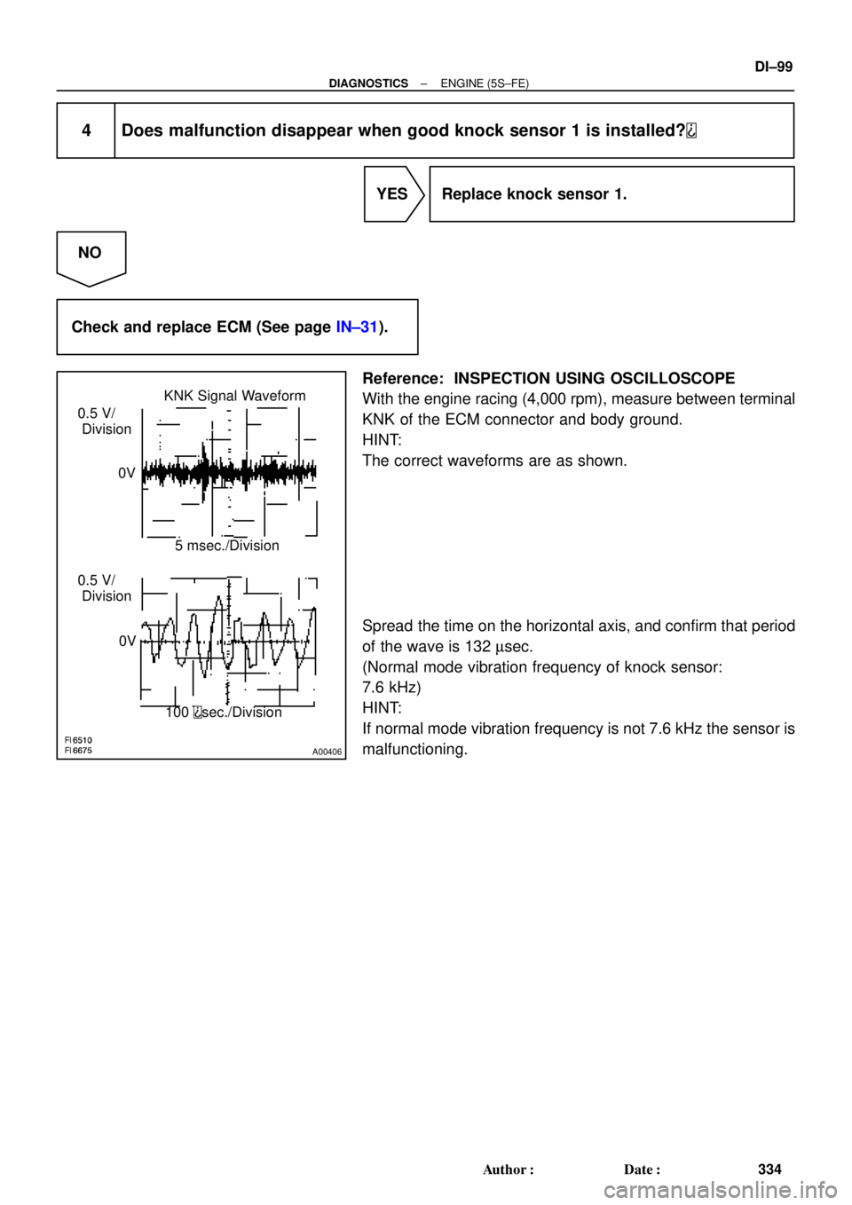
A00406
KNK Signal Waveform
0.5 V/
Division
0V
0V5 msec./Division
100
sec./Division 0.5 V/
Division
± DIAGNOSTICSENGINE (5S±FE)
DI±99
334 Author�: Date�:
4 Does malfunction disappear when good knock sensor 1 is installed?
YES Replace knock sensor 1.
NO
Check and replace ECM (See page IN±31).
Reference: INSPECTION USING OSCILLOSCOPE
With the engine racing (4,000 rpm), measure between terminal
KNK of the ECM connector and body ground.
HINT:
The correct waveforms are as shown.
Spread the time on the horizontal axis, and confirm that period
of the wave is 132 msec.
(Normal mode vibration frequency of knock sensor:
7.6 kHz)
HINT:
If normal mode vibration frequency is not 7.6 kHz the sensor is
malfunctioning.