2000 SUZUKI SWIFT key
[x] Cancel search: keyPage 13 of 447

MANUAL TRANSMISSION 7A-13
INPUT & COUNTER SHAFT
1. Input shaft 13. Input shaft 5th gear 26. Countershaft
2. Oil seal
: Apply grease 99000-25010 to oil seal lip14. 5th gear spacer 27. Countershaft 1st gear
3. Input shaft right bearing 15. 5th gear needle bearing
(separated steel cage type)28. 1st gear synchronizer ring
4. Input shaft 3rd gear 16. 5th speed synchronizer ring 29. Low speed synchronizer spring
5. Needle bearing (resin cage type) 17. 5th synchronizer spring 30. Low speed sleeve & hub
5-1. Needle bearing (resin cage type) 18. 5th speed sleeve & hub 31. Low speed synchronizer key
6. High speed synchronizer ring 19. 5th synchronizer key 32. Circlip
7. High speed synchronizer spring 20. 5th synchronizer hub plate 33. 2nd gear synchronizer outer ring
8. High speed sleeve & hub 21. Circlip 34. Needle bearing
(separated steel cage type)
9. High speed synchronizer key 22. Reverse gear shaft 34-1. Needle bearing (steel cage type)
10. Circlip 23. Reverse idler gear 35. Countershaft 2nd gear
11. Input shaft 4th gear 24. Reverse shaft washer 36. Countershaft 3rd gear
12. Input shaft left bearing 25. Countershaft right bearing 37. 3rd & 4th gear spacer
Page 23 of 447

MANUAL TRANSMISSION 7A-23
INSPECTION AND REASSEMBLY
1) Clean all components thoroughly, inspect them for any
abnormality and replace with new ones as necessary.
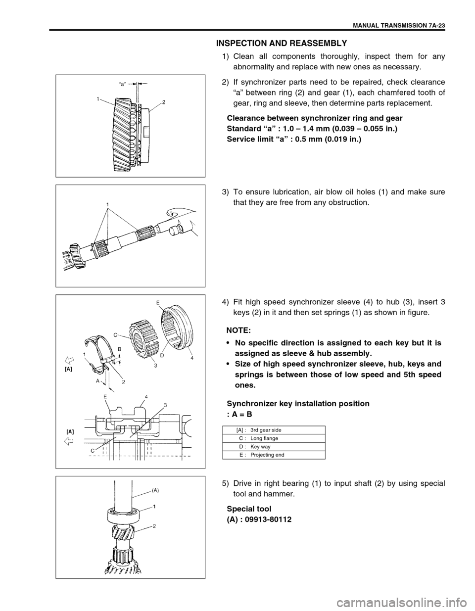
2) If synchronizer parts need to be repaired, check clearance
“a” between ring (2) and gear (1), each chamfered tooth of
gear, ring and sleeve, then determine parts replacement.
Clearance between synchronizer ring and gear
Standard “a” : 1.0 – 1.4 mm (0.039 – 0.055 in.)
Service limit “a” : 0.5 mm (0.019 in.)
3) To ensure lubrication, air blow oil holes (1) and make sure
that they are free from any obstruction.
4) Fit high speed synchronizer sleeve (4) to hub (3), insert 3
keys (2) in it and then set springs (1) as shown in figure.
Synchronizer key installation position
: A = B
5) Drive in right bearing (1) to input shaft (2) by using special
tool and hammer.
Special tool
(A) : 09913-80112
NOTE:
No specific direction is assigned to each key but it is
assigned as sleeve & hub assembly.
Size of high speed synchronizer sleeve, hub, keys and
springs is between those of low speed and 5th speed
ones.
[A] : 3rd gear side
C : Long flange
D : Key way
E : Projecting end
Page 24 of 447

7A-24 MANUAL TRANSMISSION
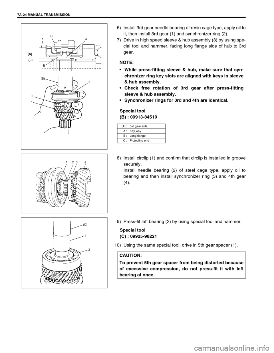
6) Install 3rd gear needle bearing of resin cage type, apply oil to
it, then install 3rd gear (1) and synchronizer ring (2).
7) Drive in high speed sleeve & hub assembly (3) by using spe-
cial tool and hammer, facing long flange side of hub to 3rd
gear.
Special tool
(B) : 09913-84510
8) Install circlip (1) and confirm that circlip is installed in groove
securely.
Install needle bearing (2) of steel cage type, apply oil to
bearing and then install synchronizer ring (3) and 4th gear
(4).
9) Press-fit left bearing (2) by using special tool and hammer.
Special tool
(C) : 09925-98221
10) Using the same special tool, drive in 5th gear spacer (1).NOTE:
While press-fitting sleeve & hub, make sure that syn-
chronizer ring key slots are aligned with keys in sleeve
& hub assembly.
Check free rotation of 3rd gear after press-fitting
sleeve & hub assembly.
Synchronizer rings for 3rd and 4th are identical.
[A] : 3rd gear side
A : Key way
B : Long flange
C : Projecting end
CAUTION:
To prevent 5th gear spacer from being distorted because
of excessive compression, do not press-fit it with left
bearing at once.
Page 27 of 447

MANUAL TRANSMISSION 7A-27
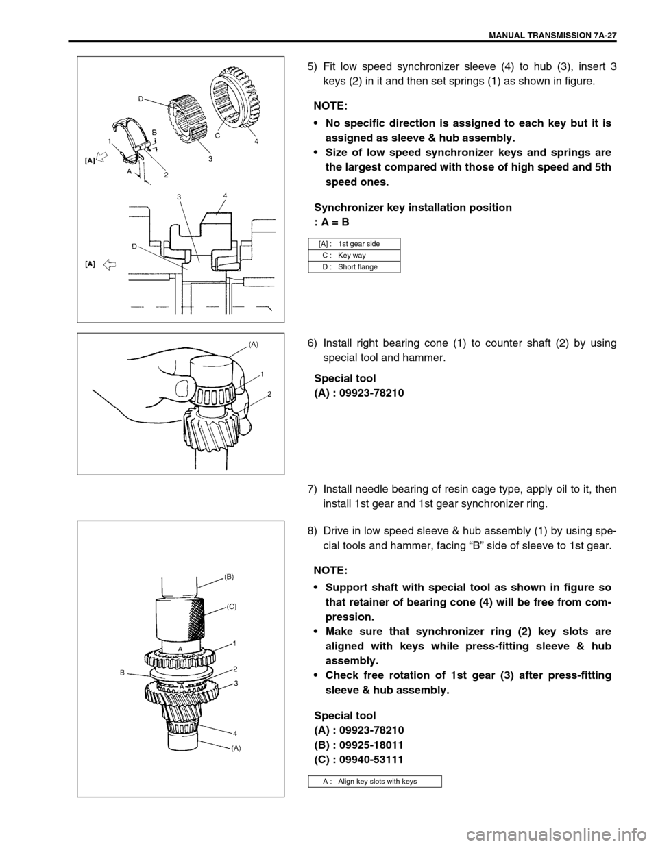
5) Fit low speed synchronizer sleeve (4) to hub (3), insert 3
keys (2) in it and then set springs (1) as shown in figure.
Synchronizer key installation position
: A = B
6) Install right bearing cone (1) to counter shaft (2) by using
special tool and hammer.
Special tool
(A) : 09923-78210
7) Install needle bearing of resin cage type, apply oil to it, then
install 1st gear and 1st gear synchronizer ring.
8) Drive in low speed sleeve & hub assembly (1) by using spe-
cial tools and hammer, facing “B” side of sleeve to 1st gear.
Special tool
(A) : 09923-78210
(B) : 09925-18011
(C) : 09940-53111 NOTE:
No specific direction is assigned to each key but it is
assigned as sleeve & hub assembly.
Size of low speed synchronizer keys and springs are
the largest compared with those of high speed and 5th
speed ones.
[A] : 1st gear side
C : Key way
D : Short flange
NOTE:
Support shaft with special tool as shown in figure so
that retainer of bearing cone (4) will be free from com-
pression.
Make sure that synchronizer ring (2) key slots are
aligned with keys while press-fitting sleeve & hub
assembly.
Check free rotation of 1st gear (3) after press-fitting
sleeve & hub assembly.
A : Align key slots with keys
Page 36 of 447

7A-36 MANUAL TRANSMISSION
Available shim thickness
0.40, 0.45, 0.50, 0.55, 0.6, 0.65,0.7, 0.75, 0.8, 0.85, 0.9, 0.95,
1.0,1.05, 1.1 and 1.15 mm (0.015, 0.017, 0.019, 0.021,
0.023,0.025, 0.027, 0.029, 0.031, 0.033,0.035, 0.037, 0.039,
0.041, 0.043 and 0.045 in.)
4) Place left case plate (2) inserting its end in groove of shift
guide shaft (4) and tighten new adhesive pre-coated
screw(s) (1) (and new adhesive per-coated bolts (7) tempo-
rarily with less than specified toque.
5) Tighten new screw(s) (and new bolts) to specified torque
finally in the order of circled numbers (➀→➁→➂→➃→➄→➅
) shown in figure.
Tightening torque
Left case plate screw(s) (and bolts)
(a) : 11 N·m (1.1 kg-m, 8.0 lb-ft)
6) Assemble 5th speed synchronizer sleeve (4) and hub (3)
with keys (2) and springs (1).
Synchronizer key installation position
: A = B
7) Install 5th gear (1) to counter shaft facing machined boss A
inward. CAUTION:
Do not reuse left case plate screw(s) (1) (and bolts (7)).
Be sure to use new adhesive pre-coated screw(s) (and
new adhesive pre-coated bolts). Otherwise, screw(s)
(and/or bolts) may loosen.
NOTE:
After tightening screw(s) (and bolts), make sure that
countershaft (5) can be rotated by hand feeling certain
load.
[A]: In case 6 screws are used 3. Input shaft
[B]: In case 1 screw and 5 bolts are used 6. Transaxle left case
NOTE:
Short side C in keys, long flange D in hub and chamfered
spline F in sleeve should face inward (5th gear side).
[A] : Short side C D : Long flange (Inward)
[B] : Long side E : Key way
C : Short side (Inward) F : Chamfered spline (Inward)
A : Machined boss (Inside)
B : No machining (Outside)
Page 44 of 447

7B-2 AUTOMATIC TRANSMISSION (4 A/T)
DTC P0702/P1702 (DTC No.52)
TRANSMISSION CONTROL SYSTEM
ELECTRICAL OR INTERNAL
MALFUNCTION OF TCM ....................... 7B-52
INSPECTION OF TCM AND ITS
CIRCUITS ............................................... 7B-53
ON-VEHICLE SERVICE ................................. 7B-55
MAINTENANCE SERVICE ......................... 7B-55
FLUID LEVEL AT NORMAL OPERATING
TEMPERATURE ..................................... 7B-55
FLUID LEVEL AT ROOM
TEMPERATURE ..................................... 7B-56
FLUID CHANGE ..................................... 7B-56
SELECTOR LEVER .................................... 7B-57
TRANSMISSION RANGE SENSOR
(SHIFT SWITCH) ........................................ 7B-58
SELECTOR CABLE .................................... 7B-60
OUTPUT SHAFT SPEED SENSOR
(A/T VSS) .................................................... 7B-62
INPUT SHAFT SPEED SENSOR ............... 7B-63
VEHICLE SPEED SENSOR (VSS)............. 7B-63
THROTTLE POSITION SENSOR............... 7B-63
ENGINE COOLANT TEMP. (ECT)
SENSOR ..................................................... 7B-64
DROPPING RESISTOR ............................. 7B-64
O/D OFF SWITCH ...................................... 7B-65
SHIFT SOLENOID VALVES AND
TRANSMISSION TEMPERATURE
SENSOR ..................................................... 7B-65
SHIFT SOLENOID VALVES ................... 7B-66
TRANSMISSION TEMPERATURE
SENSOR ................................................. 7B-66
DIFFERENTIAL SIDE OIL SEAL ................ 7B-68TRANSMISSION CONTROL MODULE
(TCM).......................................................... 7B-69
LEARNING CONTROL INITIALIZATION 7B-70
BRAKE INTERLOCK SYSTEM
(IF EQUIPPED)........................................... 7B-70
KEY INTERLOCK CABLE
(IF EQUIPPED)........................................... 7B-72
TRANSMISSION UNIT REPAIR
OVERHAUL ................................................... 7B-75
DISMOUNTING .......................................... 7B-76
REMOUNTING ........................................... 7B-77
UNIT DISASSEMBLY ................................. 7B-78
DISASSEMBLY/ASSEMBLY OF
SUBASSEMBLY ......................................... 7B-88
OIL PUMP ............................................... 7B-88
FRONT CLUTCH (C2 CLUTCH) ............ 7B-91
REAR CLUTCH (C1 CLUTCH) ............... 7B-95
DIRECT CLUTCH (C0 CLUTCH) ......... 7B-100
PLANETARY SET................................. 7B-104
VALVE BODY ....................................... 7B-106
DIFFERENTIAL ASSEMBLY ................ 7B-112
REAR COVER (O/D BRAKE PISTON
ASSEMBLY) ......................................... 7B-115
PLANETARY SUN GEAR NO.1
ASSEMBLY .......................................... 7B-115
TORQUE CONVERTER HOUSING ..... 7B-116
TRANSMISSION CASE ........................ 7B-117
UNIT ASSEMBLY ..................................... 7B-118
TIGHTENING TORQUE SPECIFICATION .. 7B-136
SPECIAL TOOL ........................................... 7B-137
REQUIRED SERVICE MATERIAL .............. 7B-139
Page 112 of 447

7B-70 AUTOMATIC TRANSMISSION (4 A/T)
LEARNING CONTROL INITIALIZATION
When one or more operations such as shown below are per-
formed, all learned contents which are stored in TCM memory
should be erased after the operations.
Replacing transmission with new or used one.
Repairing transmission partially by replacing any brake com-
ponent parts with new and/or used brake disc(s), plate(s)
and/or flange.
Repairing transmission partially by replacing any clutch com-
ponent parts with new and/or used clutch disc(s), plate(s)
and/or flange.
Replacing TCM with used one.
1) Turn ignition switch ON, leaving engine OFF.
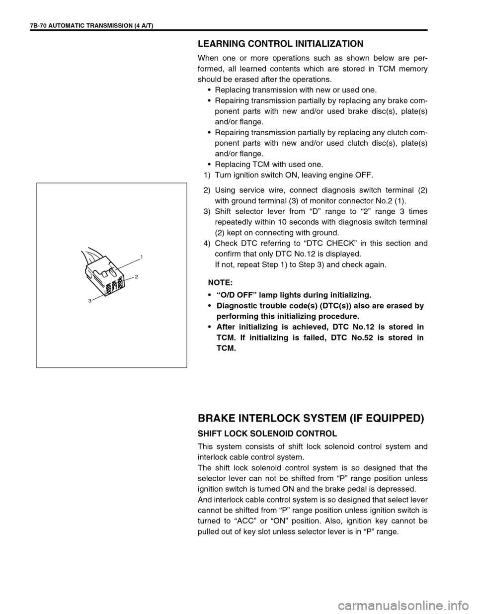
2) Using service wire, connect diagnosis switch terminal (2)
with ground terminal (3) of monitor connector No.2 (1).
3) Shift selector lever from “D” range to “2” range 3 times
repeatedly within 10 seconds with diagnosis switch terminal
(2) kept on connecting with ground.
4) Check DTC referring to “DTC CHECK” in this section and
confirm that only DTC No.12 is displayed.
If not, repeat Step 1) to Step 3) and check again.
BRAKE INTERLOCK SYSTEM (IF EQUIPPED)
SHIFT LOCK SOLENOID CONTROL
This system consists of shift lock solenoid control system and
interlock cable control system.
The shift lock solenoid control system is so designed that the
selector lever can not be shifted from “P” range position unless
ignition switch is turned ON and the brake pedal is depressed.
And interlock cable control system is so designed that select lever
cannot be shifted from “P” range position unless ignition switch is
turned to “ACC” or “ON” position. Also, ignition key cannot be
pulled out of key slot unless selector lever is in “P” range. NOTE:
“O/D OFF” lamp lights during initializing.
Diagnostic trouble code(s) (DTC(s)) also are erased by
performing this initializing procedure.
After initializing is achieved, DTC No.12 is stored in
TCM. If initializing is failed, DTC No.52 is stored in
TCM.
1
2
3
Page 113 of 447

AUTOMATIC TRANSMISSION (4 A/T) 7B-71
SHIFT LOCK SOLENOID MANUAL RLEASE
Without using brake pedal, shift lock can be moved by pushing
shift lock solenoid cam (1) with screw driver or like through hole
(2). (To shift selector lever from “P” range to any other position,
turn ignition switch to “ACC” or “ON” position.)
INSPECTION
1) Check to make sure that selector lever cannot be moved to
any other range from “P” range position when ignition switch
key is at “ACC” position, at “LOCK” position (or it is removed
from keyhole of ignition switch) or brake pedal is not
depressed.
2) Shift selector lever to “P” range position, release knob button
and check for the following.
Ignition key can be turned between “LOCK” and “ACC” posi-
tions back and forth and also it can be removed from ignition
switch.
With shift lock solenoid cam (1) moved in arrow direction and
ignition key turned to “ACC” position, selector lever can be
shifted from “P” range position to any other range.
With shift lock solenoid cam moved in arrow direction and
ignition key turned to “LOCK” position, selector lever can not
be shifted from “P” range position to any other range.
1
2
1