2000 SUZUKI SWIFT parking brake
[x] Cancel search: parking brakePage 168 of 447

7B-126 AUTOMATIC TRANSMISSION (4 A/T)
32) Install parking lock pawl (2).
33) Install parking lock pawl shaft (4), torsional spring (3), and
cover (1), then hold them with 2 bolts.
Tightening torque
Parking lock pawl bolts (a) : 11 N·m (1.1 kg-m, 8.0 lb-ft)
34) Install reverse brake (B2) plates, discs, flange and cushion
plate in following order :
(1) Cushion plate →
(2) Plate →
(3) Disc →
(4) Plate →
(5)
Disc →
(6) Plate →
(7) Disc →
(8) Plate →
(9) Disc →
(10)
Flange
35) Hold above parts with snap ring.
NOTE:
Note the direction of cushion plate (1).
Make sure that the plates are fitted into groove of
transmission case as shown in figure.
2. Brake plate side
3. Transmission case side
Page 228 of 447

7F-6 REAR DIFFERENTIAL
DIFFERENTIAL UNIT
DISMOUNTING
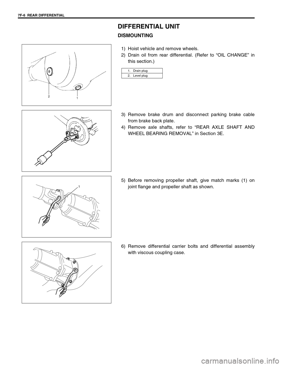
1) Hoist vehicle and remove wheels.
2) Drain oil from rear differential. (Refer to “OIL CHANGE” in
this section.)
3) Remove brake drum and disconnect parking brake cable
from brake back plate.
4) Remove axle shafts, refer to “REAR AXLE SHAFT AND
WHEEL BEARING REMOVAL” in Section 3E.
5) Before removing propeller shaft, give match marks (1) on
joint flange and propeller shaft as shown.
6) Remove differential carrier bolts and differential assembly
with viscous coupling case.
1. Drain plug
2. Level plug
1
Page 245 of 447

BODY ELECTRICAL SYSTEM 8-1
6F1
6F2
6G
6H
6K
7A
7A1
7B1
7C1
7D
7E
7F
8A
8
8D
8E
9
10
10A
10B
SECTION 8
BODY ELECTRICAL SYSTEM
CONTENTS
DIAGNOSIS ........................................................ 8-3
HEADLIGHT .................................................... 8-3
HEADLIGHTS WITH LEVELING SYSTEM
(IF EQUIPPED) ............................................... 8-3
TURN SIGNAL AND HAZARD WARNING
LIGHT .............................................................. 8-3
CLEARANCE, TAIL AND LICENSE
PLATE LIGHT ................................................. 8-4
BACK-UP LIGHT ............................................. 8-4
BRAKE LIGHT ................................................ 8-4
FRONT FOG LIGHT (IF EQUIPPED) ............. 8-4
REAR FOG LIGHT (IF EQUIPPED) ................ 8-4
SPEEDOMETER AND VSS ............................ 8-5
FUEL METER AND FUEL LEVEL SENSOR
(GAUGE UNIT) ............................................... 8-5
ENGINE COOLANT TEMPERATURE (ECT)
METER AND ECT SENSOR ........................... 8-5
OIL PRESSURE WARNING LIGHT ................ 8-5
BRAKE AND PARKING BRAKE WARNING
LIGHT .............................................................. 8-6
REAR WINDOW DEFOGGER ........................ 8-6
WIPERS AND WASHERS .............................. 8-6
FRONT WIPER AND WASHER .................. 8-6
REAR WIPER AND WASHER (IF
EQUIPPED)................................................. 8-6
POWER WINDOW CONTROL SYSTEM
(IF EQUIPPED) ............................................... 8-7
CIGARETTE LIGHTER ................................... 8-7
POWER DOOR LOCK CONTROL SYSTEM
(IF EQUIPPED) ............................................... 8-7
KEYLESS ENTRY SYSTEM (IF
EQUIPPED) .................................................... 8-7POWER DOOR MIRROR CONTROL
SYSTEM (IF EQUIPPED) ............................... 8-8
INTERIOR LIGHT ........................................... 8-8
HORN ............................................................. 8-8
IGNITION KEY REMAINDER (IF EQUIPPED)
AND LIGHT REMAINDER WARNING
BUZZER.......................................................... 8-8
SEAT BELT WARNING LIGHT (IF
EQUIPPED) .................................................... 8-8
FRONT SEAT HEATER (IF EQUIPPED) ....... 8-9
ON-VEHICLE SERVICE ..................................... 8-9
CAUTIONS IN SERVICING ............................ 8-9
HEADLIGHT ................................................... 8-9
HEADLIGHT SWITCH ................................ 8-9
HEADLIGHT ASSEMBLY ......................... 8-10
HEADLIGHT BULB ................................... 8-10
HEADLIGHT AIMING ADJUSTMENT
WITH SCREEN ......................................... 8-11
HEADLIGHT LEVELING SWITCH (IF
EQUIPPED) .............................................. 8-12
TURN SIGNAL AND HAZARD WARNING
LIGHTS ......................................................... 8-12
TURN SIGNAL LIGHT SWITCH ............... 8-12
REMOVAL AND INSTALLATION ............. 8-12
TURN SIGNAL AND HAZARD RELAY ..... 8-13
HAZARD SWITCH .................................... 8-13
FRONT FOG LIGHTS (IF EQUIPPED)......... 8-13
FRONT FOG LIGHT SWITCH .................. 8-13
REAR FOG LIGHT (IF EQUIPPED) ............. 8-14
REAR FOG LIGHT SWITCH..................... 8-14
IGNITION SWITCH ....................................... 8-14
COMBINATION METER ............................... 8-15 WARNING:
For vehicles equipped with Supplemental Restraint (Air Bag) System :
Service on and around the air bag system components or wiring must be performed only by an
authorized SUZUKI dealer. Refer to “Air Bag System Components and Wiring Location View” under
“General Description” in air bag system section in order to confirm whether you are performing ser-
vice on or near the air bag system components or wiring. Please observe all WARNINGS and “Ser-
vice Precautions” under “On-Vehicle Service” in air bag system section before performing service
on or around the air bag system components or wiring. Failure to follow WARNINGS could result in
unintentional activation of the system or could render the system inoperative. Either of these two
conditions may result in severe injury.
Technical service work must be started at least 90 seconds after the ignition switch is turned to the
“LOCK” position and the negative cable is disconnected from the battery. Otherwise, the system
may be activated by reserve energy in the Sensing and Diagnostic Module (SDM).
Page 246 of 447

8-2 BODY ELECTRICAL SYSTEM
CIRCUIT.................................................... 8-15
FUEL METER AND FUEL LEVEL
SENSOR (GAUGE UNIT) ............................. 8-16
FUEL LEVEL METER ............................... 8-16
FUEL LEVEL SENSOR (GAUGE UNIT) ... 8-17
SPEED METER AND VSS ........................... 8-17
VSS ........................................................... 8-17
ENGINE COOLANT TEMPERATURE (ECT)
METER AND SENSOR................................. 8-17
ENGINE COOLANT TEMPERATURE
(ECT) METER ........................................... 8-17
ECT SENSOR ........................................... 8-18
OIL PRESSURE WARNING LIGHT ............. 8-18
OIL PRESSURE SWITCH ........................ 8-18
BRAKE FLUID LEVEL AND PARKING
BRAKE WARNING LIGHT ............................ 8-18
BRAKE FLUID LEVEL SWITCH ............... 8-18
PARKING BRAKE SWITCH...................... 8-19
REAR WINDOW DEFOGGER...................... 8-19
DEFOGGER SWITCH .............................. 8-19
DEFOGGER WIRE ................................... 8-19
WIPERS AND WASHERS ............................ 8-21
COMPONENTS ........................................ 8-21
FRONT WIPER AND WASHER
SWITCH .................................................... 8-21
FRONT WIPER MOTOR........................... 8-23
WASHER TANK AND WASHER
PUMP ........................................................ 8-24
REAR WIPER AND WASHER SWITCH
(IF EQUIPPED) ......................................... 8-25REAR WIPER MOTOR .............................. 8-25
IGNITION KEY REMAINDER (IF EQUIPPED)
AND LIGHT REMAINDER WARNING
BUZZER ........................................................ 8-25
POWER WINDOW CONTROL SYSTEM
(IF EQUIPPED).............................................. 8-26
POWER WINDOW MAIN SWITCH ........... 8-26
POWER WINDOW SUB SWITCH ............. 8-27
DOOR SWITCH ............................................. 8-27
STOP LAMP (BRAKE) SWITCH ................... 8-27
POWER DOOR LOCK SYSTEM (IF
EQUIPPED) ................................................... 8-28
DOOR LOCK CONTROLLER .................... 8-28
DRIVER’S DOOR KNOB SWITCH ............ 8-28
DOOR LOCK ACTUATOR......................... 8-29
KEYLESS ENTRY SYSTEM (IF
EQUIPPED) ................................................... 8-29
DOOR LOCK CONTROLLER .................... 8-29
DOOR LOCK ACTUATOR......................... 8-29
RECEIVER................................................. 8-30
TRANSMITTER ......................................... 8-30
POWER DOOR MIRROR CONTROL
SYSTEM (IF EQUIPPED) .............................. 8-31
MIRROR SWITCH ..................................... 8-31
DOOR MIRROR ACTUATOR .................... 8-32
FRONT SEAT HEATER (IF EQUIPPED) ...... 8-32
SEAT HEATER SWITCH (DRIVER AND
PASSENGER SIDE) .................................. 8-32
SEAT HEATER WIRE................................ 8-33
Page 250 of 447

8-6 BODY ELECTRICAL SYSTEM
BRAKE AND PARKING BRAKE WARNING LIGHT
REAR WINDOW DEFOGGER
WIPERS AND WASHERS
FRONT WIPER AND WASHER
REAR WIPER AND WASHER (IF EQUIPPED)
Condition Possible Cause Correction
Brake warning light
does not light up
(when fluid low level
and/or parking brake
pull up)Bulb in combination meter blown Replace bulb.
Printed plate in combination meter faulty Check printed plate.
“IG/METER” fuse blown Replace fuse to check for short.
Brake fluid level switch faulty Check brake fluid level switch.
Parking brake switch faulty Check parking brake switch.
Wiring or grounding faulty Repair circuit.
Brake warning light
does not light up
when cranking (when
turned ignition switch
to ST position)Ignition switch faulty Check ignition switch.
Printed plate in combination meter faulty Check printed plate.
Wiring or grounding faulty Repair circuit.
Brake warning light
stay onBrake fluid level switch and/or parking brake
switch faultyCheck switch.
Condition Possible Cause Correction
Defogger does not
operate“REAR DEFG” fuse blown Replace fuse to check for short.
Heat wire faulty Repair heat wire.
Rear window defogger switch faulty Check switch.
Wiring or grounding faulty Repair circuit.
Condition Possible Cause Correction
Wiper malfunctions
“WIPER/WASHER” fuse blown Replace fuse to check for short.
Wiper motor faulty Check wiper motor.
Combination switch (wiper switch) faulty Check wiper switch.
Wiring or grounding faulty Repair circuit.
Washer malfunctions
Washer hose or nozzle clogged Clean or repair clogged hose or
nozzle.
“WIPER/WASHER” fuse blown Replace fuse to check for short.
Washer motor faulty Check washer motor.
Combination switch (wiper switch) faulty Check wiper switch.
Wiring or grounding faulty Repair circuit.
Page 259 of 447

BODY ELECTRICAL SYSTEM 8-15
COMBINATION METER
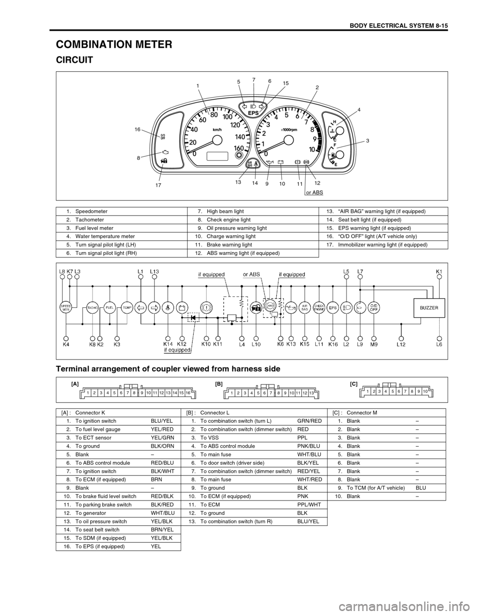
CIRCUIT
Terminal arrangement of coupler viewed from harness side
12
3 4
56 7
8
910
1112 13
14
1715
16
or ABS
1. Speedometer 7. High beam light 13.“AIR BAG” warning light (if equipped)
2. Tachometer 8. Check engine light 14. Seat belt light (if equipped)
3. Fuel level meter 9. Oil pressure warning light 15. EPS warning light (if equipped)
4. Water temperature meter 10. Charge warning light 16.“O/D OFF” light (A/T vehicle only)
5. Turn signal pilot light (LH) 11. Brake warning light 17. Immobilizer warning light (if equipped)
6. Turn signal pilot light (RH) 12. ABS warning light (if equipped)
[A] : Connector K [B] : Connector L [C] : Connector M
1. To ignition switch BLU/YEL 1. To combination switch (turn L) GRN/RED 1. Blank–
2. To fuel level gauge YEL/RED 2. To combination switch (dimmer switch) RED 2. Blank–
3. To ECT sensor YEL/GRN 3. To VSS PPL 3. Blank–
4. To ground BLK/ORN 4. To ABS control module PNK/BLU 4. Blank–
5. Blank–5. To main fuse WHT/BLU 5. Blank–
6. To ABS control module RED/BLU 6. To door switch (driver side) BLK/YEL 6. Blank–
7. To ignition switch BLK/WHT 7. To combination switch (dimmer switch) RED/YEL 7. Blank–
8. To ECM (if equipped) BRN 8. To main fuse WHT/RED 8. Blank–
9. Blank–9. To ground BLK 9. To TCM (for A/T vehicle) BLU
10. To brake fluid level switch RED/BLK 10. To ECM (if equipped) PNK 10. Blank–
11. To parking brake switch BLK/RED 11. To ECM PPL/WHT
12. To generator WHT/BLU 12. To ground BLK
13. To oil pressure switch YEL/BLK 13. To combination switch (turn R) BLU/YEL
14. To seat belt switch BRN/YEL
15. To SDM (if equipped) YEL/BLK
16. To EPS (if equipped) YEL
1 2 3 4 5 6 7 8 9 10 11 12 13 14 15 161 2 3 4 5 6 7 8 9 10 11 12 131234 567 8910[A] [B] [C]
Page 262 of 447

8-18 BODY ELECTRICAL SYSTEM
ECT SENSOR
REMOVAL, INSTALLATION AND INSPECTION
Refer to “ECT SENSOR” in Section 6E1.
OIL PRESSURE WARNING LIGHT
OIL PRESSURE SWITCH
ON-VEHICLE INSPECTION
1) Disconnect oil pressure switch (1) lead wire.
2) Check for continuity between oil pressure switch terminal (2)
and cylinder block (3) as shown in figure.
If not, replace oil pressure switch (1).
Oil pressure switch specification
During engine running : No continuity
At engine stop : Continuity
REMOVAL AND INSTALLATION
Refer to “OIL PRESSURE CHECK” in Section 6A1.
BRAKE FLUID LEVEL AND PARKING BRAKE
WARNING LIGHT
BRAKE FLUID LEVEL SWITCH
INSPECTION
Check for continuity between terminals of brake fluid level switch
coupler.
If found defective, replace switch.
Brake fluid level switch specification
OFF position (float up) : No continuity
ON position (float down) : Continuity
Page 263 of 447

BODY ELECTRICAL SYSTEM 8-19
PARKING BRAKE SWITCH
INSPECTION
Check for continuity between parking brake switch terminal and
body ground as shown in figure.
If found defective, replace switch.
Parking brake switch specification
OFF position (parking brake released) (1) :
No continuity
ON position (parking brake lever pulled up) (2) :
Continuity
REAR WINDOW DEFOGGER
DEFOGGER SWITCH
INSPECTION
Check for continuity between terminals at each switch position as
shown below. If check result is not satisfied, replace.
DEFOGGER WIRE
INSPECTION
SwitchPositionTerminal
ON (PUSH IN)IG LOAD E IL ILE
OFF
NOTE:
When cleaning rear window glass, use a dry cloth to
wipe it along heat wire (1) direction.
When cleaning glass, do not use detergent or abra-
sive-containing glass cleaner.
When measuring wire voltage, use a tester with nega-
tive probe (2) wrapped with a tin foil (3) which should
be held down on wire by finger pressure.