Page 110 of 447
7B-68 AUTOMATIC TRANSMISSION (4 A/T)
DIFFERENTIAL SIDE OIL SEAL
REPLACEMENT
1) Lift up vehicle and drain transmission oil.
2) Remove drive shaft joints from differential gear of transmis-
sion.
Refer to Section 4 for procedure to disconnect drive shaft
joints.
For differential side oil seal removal, it is not necessary to
remove drive shafts from steering knuckle.
For 4WD vehicle, remove transfer referring to Section 7D.
3) Remove differential side oil seal (1) by using flat end rod or
like.
4) Install new differential side oil seal by using special tool.
Special tool
(A) : 09940-53111
(B) : 09913-75510
5) Install drive shaft referring to Section 4.
6) Refill A/T fluid referring to “FLUID CHANGE” in this section. NOTE:
For oil seal installation, press-fit oil seal so that transmis-
sion case end face is flush with oil seal end face.
2. Steering gear box
3. A/T oil pan
4. Torque converter hous-
ing
5. Transmission case
Page 117 of 447
AUTOMATIC TRANSMISSION (4 A/T) 7B-75
TRANSMISSION UNIT REPAIR OVERHAUL
NOTE:
When transmission is replaced, or when clutch or brake disc, plate and/or flange is changed to new
and/or used one, all learned contents which are stored in TCM memory should be erased referring to
“LEARNING CONTROL INITIALIZATION” in this section.
1. Torque converter 9. Counter drive gear 17. 1st & 2nd brake (B1) assembly
2. Torque converter housing 10. Reverse brake (B2) piston assembly 18. Planetary gear assembly
3. Oil pump assembly 11. A/T oil pan 19. O/D brake (B0) assembly
4. Front clutch (C2) assembly 12. Oil strainer 20. Planetary sun gear No.1 assembly
5. Rear Clutch (C1) assembly 13. Valve body assembly 21. Direct clutch (C0) assembly
6. Reverse brake (B2) assembly 14. Transmission case 22. O/D brake (B0) piston and rear cover assembly
7. Intermediate shaft 15. Counter driven gear assembly
8. Follow shaft 16. 1st & 2nd brake (B1) piston assembly
Page 201 of 447

TRANSFER 7D-3
ON-VEHICLE SERVICE
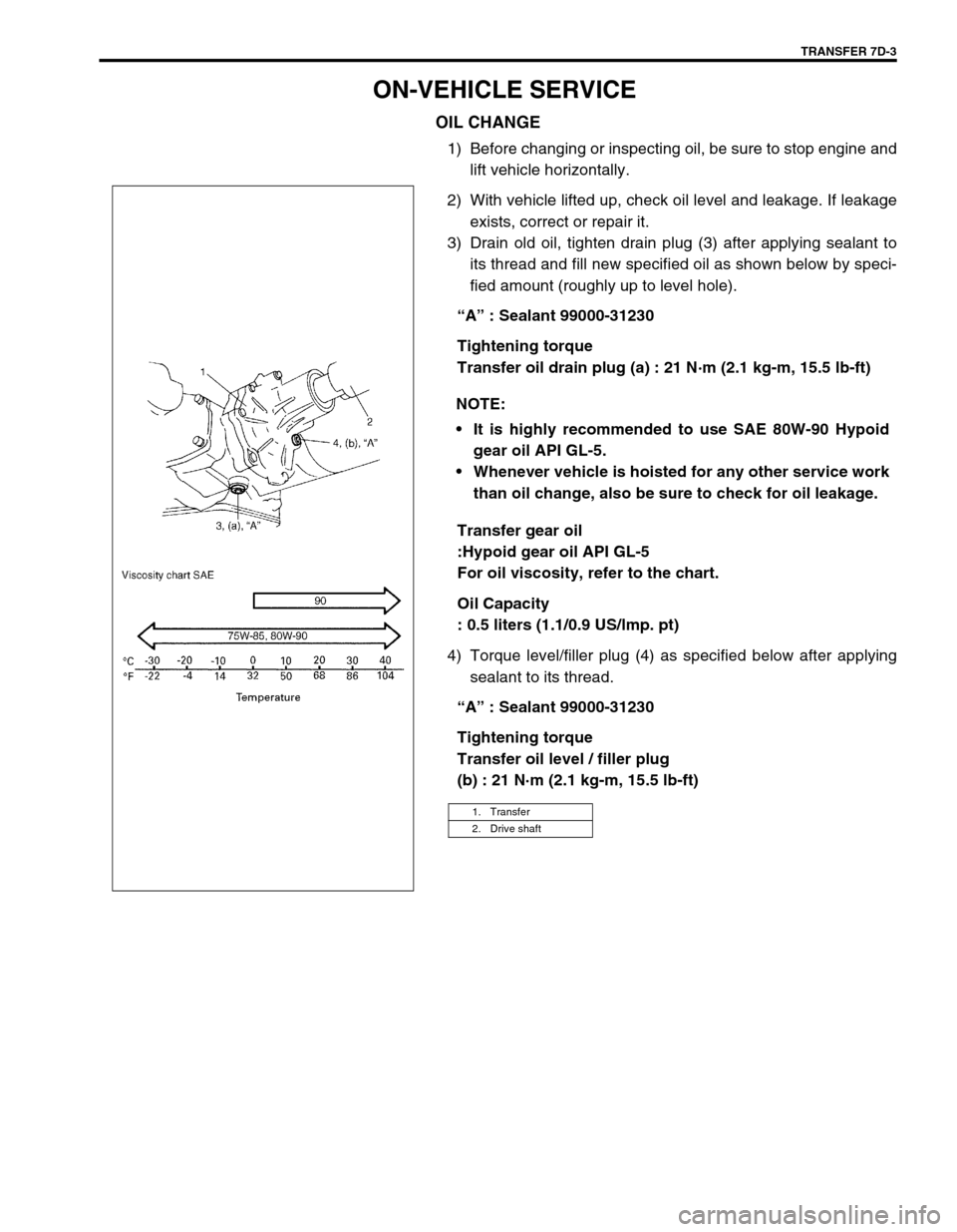
OIL CHANGE
1) Before changing or inspecting oil, be sure to stop engine and
lift vehicle horizontally.
2) With vehicle lifted up, check oil level and leakage. If leakage
exists, correct or repair it.
3) Drain old oil, tighten drain plug (3) after applying sealant to
its thread and fill new specified oil as shown below by speci-
fied amount (roughly up to level hole).
“A” : Sealant 99000-31230
Tightening torque
Transfer oil drain plug (a) : 21 N·m (2.1 kg-m, 15.5 lb-ft)
Transfer gear oil
:Hypoid gear oil API GL-5
For oil viscosity, refer to the chart.
Oil Capacity
: 0.5 liters (1.1/0.9 US/lmp. pt)
4) Torque level/filler plug (4) as specified below after applying
sealant to its thread.
“A” : Sealant 99000-31230
Tightening torque
Transfer oil level / filler plug
(b) : 21 N·m (2.1 kg-m, 15.5 lb-ft) NOTE:
It is highly recommended to use SAE 80W-90 Hypoid
gear oil API GL-5.
Whenever vehicle is hoisted for any other service work
than oil change, also be sure to check for oil leakage.
1. Transfer
2. Drive shaft
Page 219 of 447
TRANSFER 7D-21
Tighten mounting bolt and mounting bracket bolts and nuts
to specified torque.
Tightening torque
Transfer rear mounting bracket nuts
(a) : 50 N·m (5.0 kg-m, 36.5 lb-ft)
Transfer mounting bolt
(b) : 55 N·m (5.5 kg-m, 40.0 lb-ft)
Transfer rear mounting bracket No.2 bolts
(c) : 55 N·m (5.5 kg-m, 40.0 lb-ft)
Tighten transfer stiffener bolts (4) to specified torque.
Tightening torque
Transfer stiffener bolts (a) : 50 N·m (5.0 kg-m, 36.5 lb-ft)
Tighten exhaust pipe bolts.
Tightening torque
Exhaust pipe bolts
(a) : 50 N·m (5.0 kg-m, 36.5 lb-ft)
Install right side drive shaft, refer to Section 4A.
Install propeller shaft and tighten propeller shaft bolts and
center support bolts to specified torque (refer to Section 4B).
Fill gear oil to transfer as specified, refer to OIL CHANGE of
ON-VEHICLE SERVICE.
Check oil level and leakage.
(a)
(b)
(c)
1. Transmission
2. Transfer
3. Stiffener
1. Exhaust No.1 pipe
2. Exhaust No.2 pipe
1
(a)(a)2
Page 223 of 447
REAR DIFFERENTIAL 7F-1
6F1
6F2
6G
6H
6K
7A
7A1
7B1
7C1
7E
7F
7F
8B
8C
8D
8E
9
10
10A
10B
SECTION 7F
REAR DIFFERENTIAL
CONTENTS
GENERAL DESCRIPTION ............................... 7F-2
VISCOUS COUPLING .................................. 7F-2
DIAGNOSIS ...................................................... 7F-3
ON-VEHICLE SERVICE ................................... 7F-4
OIL CHANGE ................................................ 7F-4
UNIT REPAIR OVERHAUL .............................. 7F-5
DIFFERENTIAL UNIT ................................... 7F-6
UNIT DISASSEMBLY ................................... 7F-7SUB-ASSEMBLY REPAIR............................ 7F-8
VISCOUS COUPLING .............................. 7F-8
REAR DIFFERENTIAL............................ 7F-10
UNIT ASSEMBLY ....................................... 7F-20
TIGHTENING TORQUE SPECIFICATION..... 7F-20
REQUIRED SERVICE MATERIAL................. 7F-21
SPECIAL TOOL ............................................. 7F-21
Page 226 of 447

7F-4 REAR DIFFERENTIAL
ON-VEHICLE SERVICE
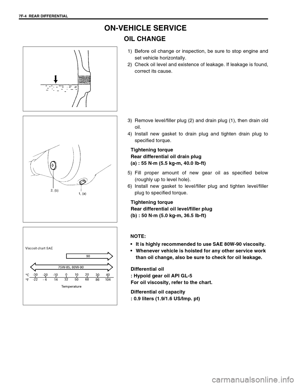
OIL CHANGE
1) Before oil change or inspection, be sure to stop engine and
set vehicle horizontally.
2) Check oil level and existence of leakage. If leakage is found,
correct its cause.
3) Remove level/filler plug (2) and drain plug (1), then drain old
oil.
4) Install new gasket to drain plug and tighten drain plug to
specified torque.
Tightening torque
Rear differential oil drain plug
(a) : 55 N·m (5.5 kg-m, 40.0 lb-ft)
5) Fill proper amount of new gear oil as specified below
(roughly up to level hole).
6) Install new gasket to level/filler plug and tighten level/filler
plug to specified torque.
Tightening torque
Rear differential oil level/filler plug
(b) : 50 N·m (5.0 kg-m, 36.5 lb-ft)
Differential oil
: Hypoid gear oil API GL-5
For oil viscosity, refer to the chart.
Differential oil capacity
: 0.9 liters (1.9/1.6 US/Imp. pt)
NOTE:
It is highly recommended to use SAE 80W-90 viscosity.
Whenever vehicle is hoisted for any other service work
than oil change, also be sure to check for oil leakage.
Page 228 of 447
7F-6 REAR DIFFERENTIAL
DIFFERENTIAL UNIT
DISMOUNTING
1) Hoist vehicle and remove wheels.
2) Drain oil from rear differential. (Refer to “OIL CHANGE” in
this section.)
3) Remove brake drum and disconnect parking brake cable
from brake back plate.
4) Remove axle shafts, refer to “REAR AXLE SHAFT AND
WHEEL BEARING REMOVAL” in Section 3E.
5) Before removing propeller shaft, give match marks (1) on
joint flange and propeller shaft as shown.
6) Remove differential carrier bolts and differential assembly
with viscous coupling case.
1. Drain plug
2. Level plug
1
Page 229 of 447

REAR DIFFERENTIAL 7F-7
REMOUNTING
Reverse removal procedure for installation, noting the following.
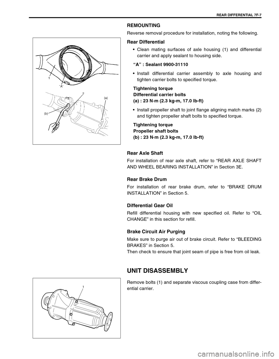
Rear Differential
Clean mating surfaces of axle housing (1) and differential
carrier and apply sealant to housing side.
“A” : Sealant 9900-31110
Install differential carrier assembly to axle housing and
tighten carrier bolts to specified torque.
Tightening torque
Differential carrier bolts
(a) : 23 N·m (2.3 kg-m, 17.0 lb-ft)
Install propeller shaft to joint flange aligning match marks (2)
and tighten propeller shaft bolts to specified torque.
Tightening torque
Propeller shaft bolts
(b) : 23 N·m (2.3 kg-m, 17.0 lb-ft)
Rear Axle Shaft
For installation of rear axle shaft, refer to “REAR AXLE SHAFT
AND WHEEL BEARING INSTALLATION” in Section 3E.
Rear Brake Drum
For installation of rear brake drum, refer to “BRAKE DRUM
INSTALLATION” in Section 5.
Differential Gear Oil
Refill differential housing with new specified oil. Refer to “OIL
CHANGE” in this section for refill.
Brake Circuit Air Purging
Make sure to purge air out of brake circuit. Refer to “BLEEDING
BRAKES” in Section 5.
Then check to ensure that joint seam of pipe is free from oil leak.
UNIT DISASSEMBLY
Remove bolts (1) and separate viscous coupling case from differ-
ential carrier.1