Page 300 of 557

1
2
ENGINE MECHANICAL (G13B, 1-CAM 16-VALVES ENGINE) 6A1-5
ON-VEHICLE SERVICE
COMPRESSION CHECK
Check compression pressure on all four cylinders as follows:
1) Warm up engine.
2) Stop engine after warming up.
NOTE:
After warming up engine, place transmission gear shift le-
ver in “Neutral” (shift selector lever to “P” range for A / T
model), and set parking brake and block drive wheels.
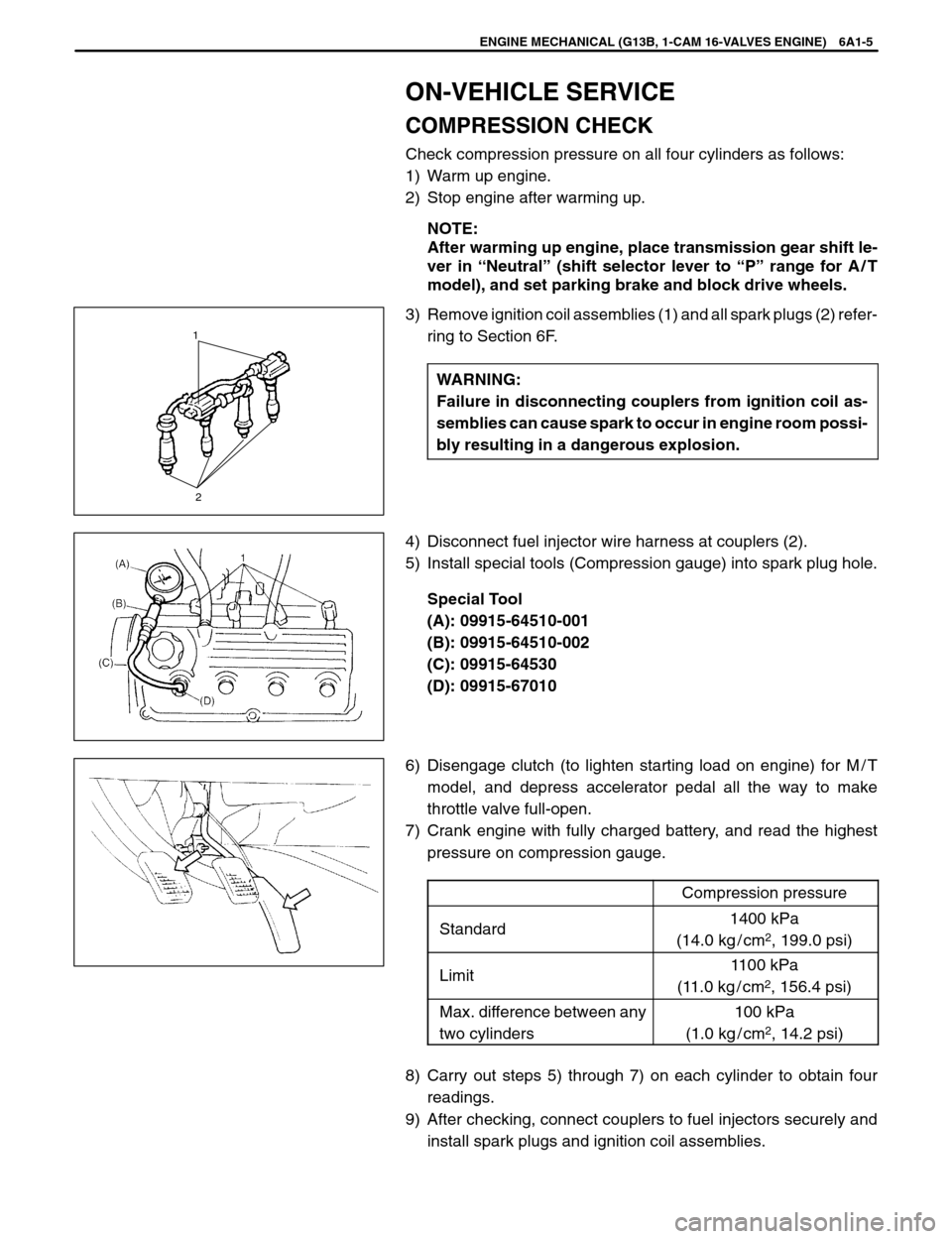
3) Remove ignition coil assemblies (1) and all spark plugs (2) refer-
ring to Section 6F.
WARNING:
Failure in disconnecting couplers from ignition coil as-
semblies can cause spark to occur in engine room possi-
bly resulting in a dangerous explosion.
4) Disconnect fuel injector wire harness at couplers (2).
5) Install special tools (Compression gauge) into spark plug hole.
Special Tool
(A): 09915-64510-001
(B): 09915-64510-002
(C): 09915-64530
(D): 09915-67010
6) Disengage clutch (to lighten starting load on engine) for M / T
model, and depress accelerator pedal all the way to make
throttle valve full-open.
7) Crank engine with fully charged battery, and read the highest
pressure on compression gauge.
Compression pressure
Standard1400 kPa
(14.0 kg / cm
2, 199.0 psi)
Limit1100 kPa
(11.0 kg / cm
2, 156.4 psi)
Max. difference between any
two cylinders100 kPa
(1.0 kg / cm
2, 14.2 psi)
8) Carry out steps 5) through 7) on each cylinder to obtain four
readings.
9) After checking, connect couplers to fuel injectors securely and
install spark plugs and ignition coil assemblies.
Page 312 of 557
: Tightening Torque
: Do not reuse
1. Exhaust manifold
2. Gasket
3. Cover
4. Heated oxygen sensor
7. Gasket
8. Exhaust No.1 pipe.
21
ENGINE MECHANICAL (G13B, 1-CAM 16-VALVES ENGINE) 6A1-17
EXHAUST MANIFOLD
WARNING:
To avoid danger of being burned, do not service exhaust
system while it is still hot.
Service should be performed after system cools down.
REMOVAL
1) Disconnect negative cable at battery.
2) Disconnect heated oxygen sensor coupler.
Release its wire from clamps.
3) Disconnect exhaust No.1 pipe (1) from WU-TWC.
4) Remove WU-TWC stiffener (2) (if equipped).
5) Remove exhaust manifold (1) and its gasket from cylinder head.
Page 366 of 557

1. Gaging plastic
ENGINE MECHANICAL (G13B, 1-CAM 16-VALVES ENGINE) 6A1-71
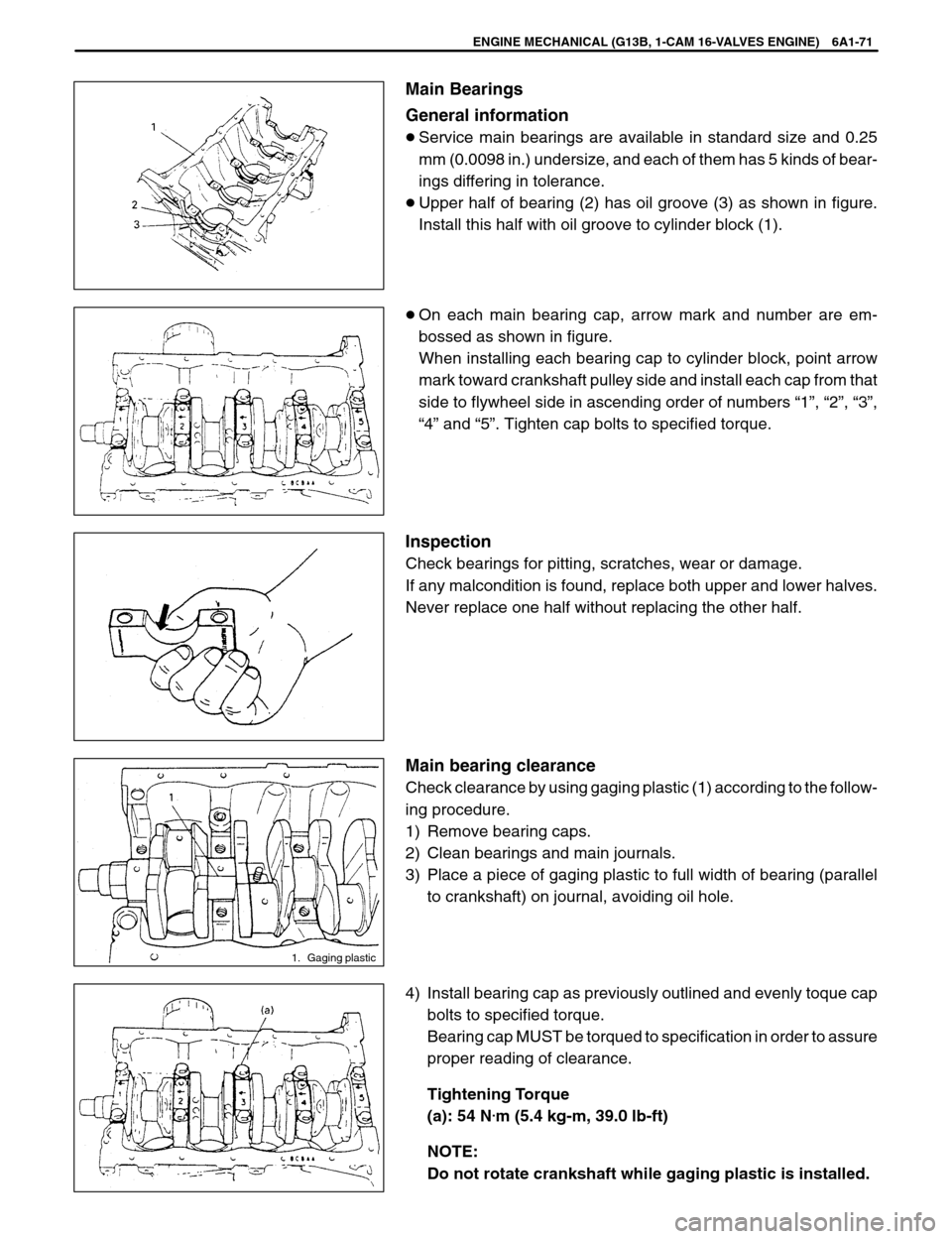
Main Bearings
General information
�Service main bearings are available in standard size and 0.25
mm (0.0098 in.) undersize, and each of them has 5 kinds of bear-
ings differing in tolerance.
�Upper half of bearing (2) has oil groove (3) as shown in figure.
Install this half with oil groove to cylinder block (1).
�On each main bearing cap, arrow mark and number are em-
bossed as shown in figure.
When installing each bearing cap to cylinder block, point arrow
mark toward crankshaft pulley side and install each cap from that
side to flywheel side in ascending order of numbers “1”, “2”, “3”,
“4” and “5”. Tighten cap bolts to specified torque.
Inspection
Check bearings for pitting, scratches, wear or damage.
If any malcondition is found, replace both upper and lower halves.
Never replace one half without replacing the other half.
Main bearing clearance
Check clearance by using gaging plastic (1) according to the follow-
ing procedure.
1) Remove bearing caps.
2) Clean bearings and main journals.
3) Place a piece of gaging plastic to full width of bearing (parallel
to crankshaft) on journal, avoiding oil hole.
4) Install bearing cap as previously outlined and evenly toque cap
bolts to specified torque.
Bearing cap MUST be torqued to specification in order to assure
proper reading of clearance.
Tightening Torque
(a): 54 N
.m (5.4 kg-m, 39.0 lb-ft)
NOTE:
Do not rotate crankshaft while gaging plastic is installed.
Page 376 of 557
09917-98221
Valve stem seal installer09916-77310
Piston ring compressor09924-17810
Flywheel holder09915-47330
Oil filter wrench
ENGINE MECHANICAL (G13B, 1-CAM 16-VALVES ENGINE) 6A1-81
REQUIRED SERVICE MATERIALS
MATERIALSRECOMMENDED
SUZUKI PRODUCTUSE
SealantSUZUKI BOND NO.1207C
(99000-31150)�Mating surfaces of cylinder block and oil pan.
SealantSUZUKI BOND NO.1215
(99000-31110)�Mating surfaces of camshaft housings (No.6).
�Mating surfaces of CMP sensor case and cylinder
block.
Page 378 of 557

6B
ENGINE COOLING 6B-1
SECTION 6B
ENGINE COOLING
NOTE:
For the descriptions (items) not found in this section, refer to the same section of Service Manual men-
tioned in FOREWORD of this manual.
CONTENTS
GENERAL DESCRIPTION6B-2 . . . . . . . . . . . . . . . . . . . . . . . . . . . . . . . . . . . . . . . . . . . . . . . . . . . . . . . . . . . . . . . . . .
DIAGNOSIS6B-4 . . . . . . . . . . . . . . . . . . . . . . . . . . . . . . . . . . . . . . . . . . . . . . . . . . . . . . . . . . . . . . . . . . . . . . . . . . . . . . .
MAINTENANCE6B-5 . . . . . . . . . . . . . . . . . . . . . . . . . . . . . . . . . . . . . . . . . . . . . . . . . . . . . . . . . . . . . . . . . . . . . . . . . . .
Coolant6B-5 . . . . . . . . . . . . . . . . . . . . . . . . . . . . . . . . . . . . . . . . . . . . . . . . . . . . . . . . . . . . . . . . . . . . . . . . . . . . . . . . .
Cooling System Flush and Refill 6B-6. . . . . . . . . . . . . . . . . . . . . . . . . . . . . . . . . . . . . . . . . . . . . . . . . . . . . . . . . . . .
ON-VEHICLE SERVICE6B-7 . . . . . . . . . . . . . . . . . . . . . . . . . . . . . . . . . . . . . . . . . . . . . . . . . . . . . . . . . . . . . . . . . . . .
Coolant Water Pipes or Hoses6B-7 . . . . . . . . . . . . . . . . . . . . . . . . . . . . . . . . . . . . . . . . . . . . . . . . . . . . . . . . . . . . .
Thermostat6B-7 . . . . . . . . . . . . . . . . . . . . . . . . . . . . . . . . . . . . . . . . . . . . . . . . . . . . . . . . . . . . . . . . . . . . . . . . . . . . . .
Water Pump6B-9 . . . . . . . . . . . . . . . . . . . . . . . . . . . . . . . . . . . . . . . . . . . . . . . . . . . . . . . . . . . . . . . . . . . . . . . . . . . . .
Page 384 of 557
1. Radiator hose
2. Clamp
ENGINE COOLING 6B-7
ON-VEHICLE SERVICE
WARNING:
�Check to make sure that engine coolant temperature is
cold before removing any part of cooling system.
�Also be sure to disconnect negative cord from battery ter-
minal before removing any part.
COOLING WATER PIPES OR HOSES
REMOVAL
1) Drain cooling system.
2) To remove these pipes or hoses, loosen screw on each pipe or
hose clip and pull hose end off.
INSTALLATION
Install removed parts in reverse order of removal procedure, noting
the following.
�Tighten each clamp bolt securely.
�Refill cooling system with proper coolant, referring to description
on COOLANT of MAINTENANCE.
THERMOSTAT
REMOVAL
1) Disconnect negative cable at battery.
2) Drain cooling system and tighten drain plug.
3) Disconnect thermostat cap (1) from thermostat case (2).
Page 388 of 557

6C
ENGINE FUEL 6C-1
GENERAL DESCRIPTION6C-1 . . . . . . . . . . . . . .
Fuel System 6C-1. . . . . . . . . . . . . . . . . . . . . . . . . . .
Fuel Pump Assembly 6C-1. . . . . . . . . . . . . . . . . . . ON-VEHICLE SERVICE6C-2 . . . . . . . . . . . . . . . .
Fuel Lines 6C-2. . . . . . . . . . . . . . . . . . . . . . . . . . .
Fuel Tank 6C-2. . . . . . . . . . . . . . . . . . . . . . . . . . .
Fuel Pump Assembly 6C-4. . . . . . . . . . . . . . . . .
SECTION 6C
ENGINE FUEL
NOTE:
For the descriptions (items) not found in this section, refer to the same section of Service Manual men-
tioned in FOREWORD of this manual.
CONTENTS
CAUTION:
BE SURE TO USE UNLEADED FUEL ONLY. USE OF LEADED AND / OR LOW LEAD FUEL CAN RESULT
IN ENGINE DAMAGE AND REDUCE THE EFFECTIVENESS OF THE EMISSION CONTROL SYSTEM.
GENERAL DESCRIPTION
FUEL SYSTEM
The main components of the fuel system are fuel tank, fuel pump, fuel filter and fuel level gauge and it includes
three lines; fuel feed line, fuel return line and fuel vapor line.
For the details of fuel vapor flow, refer to Section 6E “ENGINE AND EMISSION CONTROL SYSTEM”.
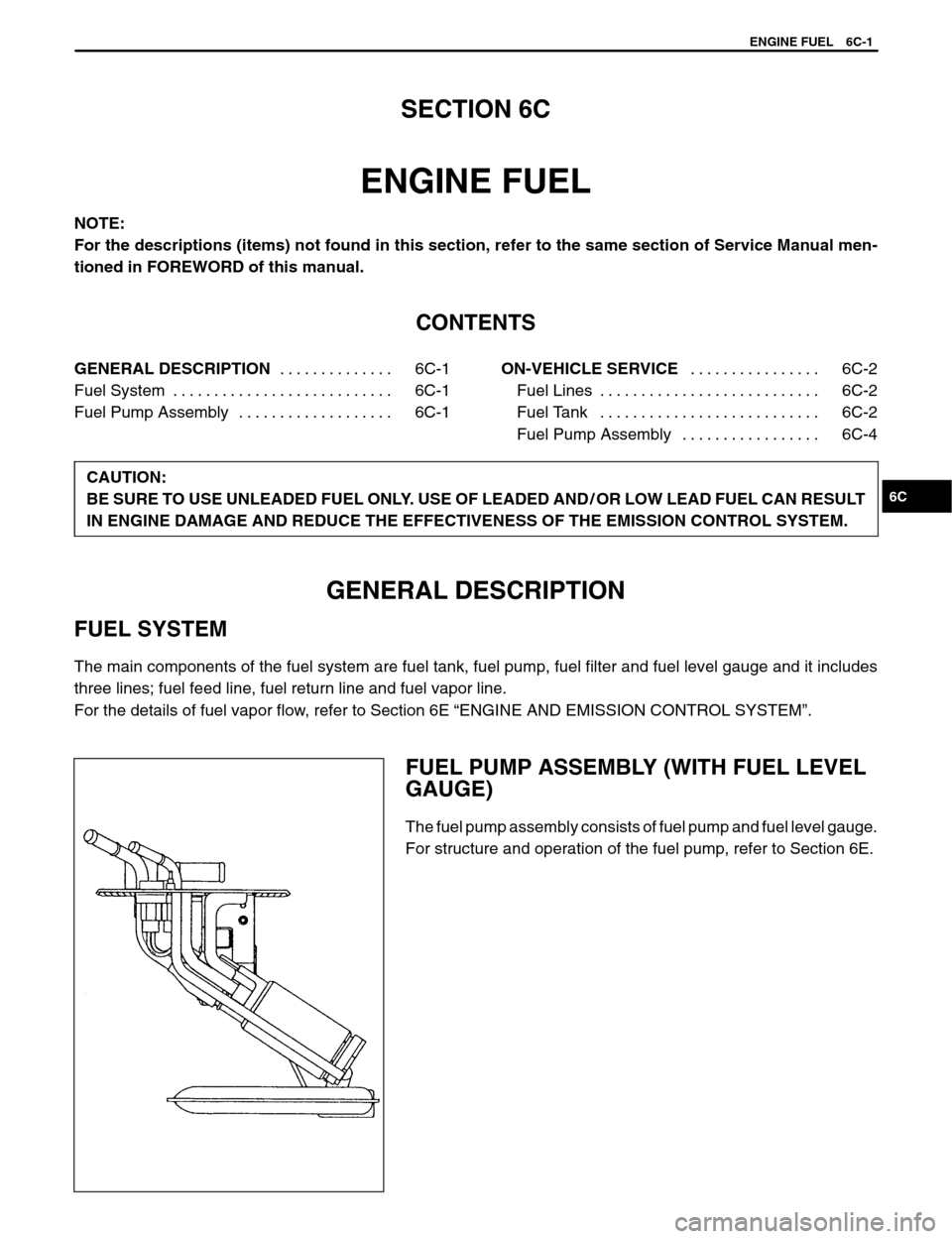
FUEL PUMP ASSEMBLY (WITH FUEL LEVEL
GAUGE)
The fuel pump assembly consists of fuel pump and fuel level gauge.
For structure and operation of the fuel pump, refer to Section 6E.
Page 389 of 557
1. Fuel tank
2. Fuel pump and level gauge
3. Fuel filler cap
4. 2-way check valve
5. Breather hose
6. Fuel feed line
7. Fuel return line
8. Fuel vapor line
9. Fuel cut valve
10. Fuel tank pad
11. Fuel tank fixer bolt
: Tightening Torque
6C-2 ENGINE FUEL
ON-VEHICLE SERVICE
FUEL LINES
INSPECTION
Visually inspect fuel lines for evidence of fuel leakage, hose crack
and deterioration, or damage.
Make sure all clamps are secure.
Replace parts as needed.
FUEL TANK
REMOVAL
1) Relieve fuel pressure in fuel feed line according to procedure de-
scribed in Section 6.
2) Disconnect negative cable at battery.
3) Remove rear seat cushion referring to Section 9.
4) Disconnect connectors (1) of fuel tank wire harness.
5) Hoist vehicle.
6) Disconnect fuel filler hose (3) from fuel tank and breather hose
(2) from filler neck (1).