2000 SUZUKI SWIFT injector
[x] Cancel search: injectorPage 11 of 698

0A-8 GENERAL INFORMATION
Make sure that all parts used in reassembly are perfectly
clean.
When use of a certain type of lubricant, bond or sealant
is specified, be sure to use the specified type.
“A” : Sealant 99000-31150
Be sure to use special tools when instructed.
Special Tool
(A) : 09917-98221
(B) : 09916-58210
When disconnecting vacuum hoses, attach a tag
describing the correct installation positions so that the
hoses can be reinstalled correctly.
After servicing fuel, oil, coolant, vacuum, exhaust or
brake systems, check all lines related to the system for
leaks.
For vehicles equipped with fuel injection systems, never
disconnect the fuel line between the fuel pump and
injector without first releasing the fuel pressure, or fuel
can be sprayed out under pressure.
When performing a work that produces a heat exceeding
80°C (176°F) in the vicinity of the electrical parts, remove
the heat sensitive electrical part(s) beforehand.
Page 372 of 698

ENGINE GENERAL INFORMATION AND DIAGNOSIS 6-3
DTC P1500 ENGINE STARTER SIGNAL
CIRCUIT MALFUNCTION ........................... 6-110
DTC P1510 ECM BACK-UP POWER
SUPPLY MALFUNCTION ........................... 6-111
DTC P1600 SERIAL COMMUNICATION
PROBLEM BETWEEN ECM AND TCM...... 6-112
DTC P1717 A/T DRIVE RANGE (PARK/
NEUTRAL POSITION) SIGNAL CIRCUIT
MALFUNCTION .......................................... 6-114
TABLE B-1 FUEL INJECTOR CIRCUIT
CHECK ........................................................ 6-117
TABLE B-2 FUEL PUMP AND ITS CIRCUIT CHECK ....................................................... 6-118
TABLE B-3 FUEL PRESSURE CHECK ..... 6-120
TABLE B-4 IDLE AIR CONTROL
SYSTEM CHECK........................................ 6-122
TABLE B-5 A/C SIGNAL CIRCUITS
CHECK (VEHICLE WITH A/C) ................... 6-124
TABLE B-6 ELECTRIC LOAD SIGNAL
CIRCUIT CHECK ........................................ 6-126
TABLE B-7 RADIATOR FAN CONTROL
SYSTEM CHECK........................................ 6-128
SPECIAL TOOL ............................................. 6-130
Page 374 of 698

ENGINE GENERAL INFORMATION AND DIAGNOSIS 6-5
PRECAUTION ON FUEL SYSTEM SERVICE
Work must be done with no smoking, in a well-ventilated
area and away from any open flames.
As fuel feed line (between fuel pump and fuel delivery pipe)
is still under high fuel pressure even after engine was
stopped, loosening or disconnecting fuel feed line directly
may cause dangerous spout of fuel to occur where loosened
or disconnected.
Before loosening or disconnecting fuel feed line, make sure
to release fuel pressure according to “FUEL PRESSURE
RELIEF PROCEDURE”. A small amount of fuel may be
released after the fuel line is disconnected. In order to
reduce the chance of personal injury, cover the fitting to be
disconnected with a shop cloth. Put that cloth in an approved
container when disconnection is completed.
Never run engine with fuel pump relay disconnected when
engine and exhaust system are hot.
Fuel or fuel vapor hose connection varies with each type of
pipe. When reconnecting fuel or fuel vapor hose, be sure to
connect and clamp each hose correctly referring to figure
Hose Connection.
After connecting, make sure that it has no twist or kink.
When installing injector or fuel delivery pipe, lubricate its O-
ring with spindle oil or gasoline.
When connecting fuel pipe flare nut, first tighten flare nut by
hand and then tighten it to specified torque.
[A] : With short pipe, fit hose as far as it reaches pipe joint as shown.
[B] : With following type pipe, fit hose as far as its peripheral projection as shown.
[C] : With bent pipe, fit hose as its bent part as shown or till pipe is about 20 to 30 mm
(0.79–1.18 in.) into the hose.
[D] : With straight pipe, fit hose till pipe is, about 20 to 30 mm (0.79–1.18 in.) into the
hose.
1. Hose
2. Pipe
3. Clamp
4. Clamp securely at a position 3 to 7 mm (0.1 2–0.27 in.) from hose end.
5. 20 to 30 mm (0.79–1.18 in.)
Page 393 of 698

6-24 ENGINE GENERAL INFORMATION AND DIAGNOSIS
Fig. 1 for Step 5
Fig. 2 for Step 611 Check ignition spark as follows :
1) Disconnect injector couplers.
2) Remove spark plugs and connect them to
high tension cords.
3) Ground spark plugs.
4) Crank engine and check if each spark plug
sparks.
Is it in good condition?Go to Step 12. Go to “DIAGNOSIS” in
Section 6F1.
12 Check fuel injector for operation as follows :
1) Install spark plugs and connect injector con-
nectors.
2) Using sound scope (1), check operating
sound of each injector (2) when cranking
engine. See Fig. 6.
Was injector operating sound heard from all
injectors?Go to “ENGINE DIAGNO-
SIS TABLE”.Go to “DIAG. FLOW
TABLE B-1”. Step Action Yes No
[A] : When not using SUZUKI scan tool:[A]
Page 397 of 698
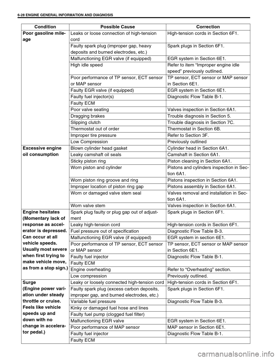
6-28 ENGINE GENERAL INFORMATION AND DIAGNOSIS
Poor gasoline mile-
age Leaks or loose connection of high-tension
cordHigh-tension cords in Section 6F1.
Faulty spark plug (improper gap, heavy
deposits and burned electrodes, etc.)Spark plugs in Section 6F1.
Malfunctioning EGR valve (if equipped) EGR system in Section 6E1.
High idle speed Refer to item “Improper engine idle
speed” previously outlined.
Poor performance of TP sensor, ECT sensor
or MAP sensorTP sensor, ECT sensor or MAP sensor
in Section 6E1.
Faulty EGR valve (if equipped) EGR system in Section 6E1.
Faulty fuel injector(s) Diagnostic Flow Table B-1.
Faulty ECM
Poor valve seating Valves inspection in Section 6A1.
Dragging brakes Trouble diagnosis in Section 5.
Slipping clutch Trouble diagnosis in Section 7C.
Thermostat out of order Thermostat in Section 6B.
Improper tire pressure Refer to Section 3F.
Low Compression Previously outlined
Excessive engine
oil consumption Blown cylinder head gasket Cylinder head in Section 6A1.
Leaky camshaft oil seals Camshaft in Section 6A1.
Sticky piston ring Piston cleaning in Section 6A1.
Worn piston and cylinder Pistons and cylinders inspection in Sec-
tion 6A1.
Worn piston ring groove and ring Pistons inspection in Section 6A1.
Improper location of piston ring gap Pistons assembly in Section 6A1.
Worn or damaged valve stem seal Valves removal and installation in Sec-
tion 6A1.
Worn valve stem Valves inspection in Section 6A1.
Engine hesitates
(Momentary lack of
response as accel-
erator is depressed.
Can occur at all
vehicle speeds.
Usually most severe
when first trying to
make vehicle move,
as from a stop sign.)Spark plug faulty or plug gap out of adjust-
mentSpark plugs in Section 6F1.
Leaky high-tension cord High-tension cords in Section 6F1.
Fuel pressure out of specification Diagnostic Flow Table B-3.
Malfunctioning EGR valve (if equipped) EGR system in section 6E1.
Poor performance of TP sensor, ECT sensor
or MAP sensorTP sensor, ECT sensor or MAP sensor
in Section 6E1.
Faulty fuel injector Diagnostic Flow Table B-1.
Faulty ECM
Engine overheating Refer to “Overheating” section.
Low compression Previously outlined.
Surge
(Engine power vari-
ation under steady
throttle or cruise.
Feels like vehicle
speeds up and
down with no
change in accelera-
tor pedal.)Leaky or loosely connected high-tension cord High-tension cords in Section 6F1.
Faulty spark plug (excess carbon deposits,
improper gap, and burned electrodes, etc.)Spark plugs in Section 6F1.
Variable fuel pressure Diagnostic Flow Table B-3.
Kinky or damaged fuel hose and lines
Faulty fuel pump (clogged fuel filter)
Malfunctioning EGR valve EGR system in Section 6E1.
Poor performance of MAP sensor MAP sensor in Section 6E1.
Faulty fuel injector Diagnostic Flow Table B-1.
Faulty ECM Condition Possible Cause Correction
Page 398 of 698

ENGINE GENERAL INFORMATION AND DIAGNOSIS 6-29
Excessive detona-
tion
(Engine makes con-
tinuously sharp
metallic knocks that
change with throttle
opening. Sounds
like pop corn pop-
ping.)Faulty spark plug Spark plugs in Section 6F1.
Loose connection of high-tension cord High-tension cords in Section 6F1.
Engine overheating Refer to “Overheating” section.
Clogged fuel filter (faulty fuel pump) or fuel
linesDiagnostic Flow Table B-1 or B-2.
Air inhaling from intake manifold or throttle
body gasket
Malfunctioning EGR valve (if equipped) EGR system in Section 6E1.
Poor performance of knock sensor, ECT sen-
sor or MAP sensorKnock sensor in Section 6, ECT sensor
or MAP sensor in Section 6E1.
Faulty fuel injector(s) Diagnostic Flow Table B-1.
Faulty ECM
Excessive combustion chamber deposits Piston and cylinder head cleaning in
Section 6A1.
Engine has no
powerFaulty spark plug Spark plugs in Section 6F1.
Faulty ignition coil with ignitor Ignition coil in Section 6F1.
Leaks, loose connection or disconnection of
high-tension cordHigh-tension cords in Section 6F1.
Faulty knock sensor Knock sensor malfunction in this sec-
tion.
Clogged fuel hose or pipe Diagnostic Flow Table B-3.
Malfunctioning fuel pump Diagnostic Flow Table B-2.
Air inhaling from intake manifold gasket or
throttle body gasket
Engine overheating Refer to “Overheating” section.
Engine has no
powerMalfunctioning EGR valve (if equipped) EGR system inspection in Section 6E1.
Maladjusted accelerator cable play Accelerator cable play in Section 6E1.
Poor performance of TP sensor, ECT sensor
or MAP sensorTP sensor, ECT sensor or MAP sensor
in Section 6E1.
Faulty fuel injector(s) Diagnostic Flow Table B-1.
Faulty ECM
Dragging brakes Trouble diagnosis in Section 5.
Slipping clutch Trouble diagnosis in Section 7C.
Low compression Previously outlined. Condition Possible Cause Correction
Page 399 of 698

6-30 ENGINE GENERAL INFORMATION AND DIAGNOSIS
Improper engine
idling or engine fails
to idleFaulty spark plug Spark plugs in Section 6F1.
Leaky or disconnected high-tension cord High-tension cords in Section 6F1.
Faulty ignition coil with ignitor Ignition coil in Section 6F1.
Fuel pressure out of specification Diagnostic Flow Table B-3.
Leaky manifold, throttle body, or cylinder
head gasket
Malfunctioning EGR valve (if equipped) EGR system in Section 6E1.
Faulty idle air control system Diagnostic Flow Table B-4.
Faulty evaporative emission control system EVAP control system in Section 6E1.
Faulty EGR system (if equipped) EGR system in Section 6E1.
Faulty fuel injector(s) Diagnostic Flow Table B-1.
Poor performance of ECT sensor, TP sensor
or MAP sensorECT sensor, TP sensor or MAP sensor
in Section 6E1.
Faulty ECM
Loose connection or disconnection of vacuum
hoses
Malfunctioning PCV valve PCV system in Section 6E1.
Engine overheating Refer to “Overheating” section.
Low compression Previously outlined.
Excessive hydrocar-
bon (HC) emission
or carbon monox-
ide (CO)Faulty spark plug Spark plugs in Section 6F1.
Leaky or disconnected high-tension cord High-tension cords in Section 6F1.
Faulty ignition coil with ignitor Ignition coil assembly in Section 6F1.
Low compression Refer to “Low compression” section.
Lead contamination of three way catalytic
converterCheck for absence of filler neck restric-
tor.
Faulty evaporative emission control system EVAP control system in Section 6E1.
Fuel pressure out of specification Diagnostic Flow Table B-3.
Closed loop system (A/F feed back compen-
sation) fails
Faulty TP sensor
Poor performance of ECT sensor or MAP
sensorTP sensor in Section 6E1.
ECT sensor or MAP sensor in Section
6E1.
Faulty injector(s) Diagnostic Flow Table B-1
Faulty ECM
Engine not at normal operating temperature
Clogged air cleaner
Vacuum leaks
Excessive nitrogen
oxides (NOx) emis-
sionImproper ignition timing See section 6F1.
Lead contamination of catalytic converter Check for absence of filler neck restric-
tor.
Faulty EGR system (if equipped) EGR system in Section 6E1.
Fuel pressure out of specification Diagnostic Flow Table B-3.
Closed loop system (A/F feed back compen-
sation) fails
Faulty TP sensor
Poor performance of ECT sensor or MAP
sensorTP sensor in Section 6E1.
ECT sensor or MAP sensor in Section
6E1.
Faulty injector(s) Diagnostic Flow Table B-1
Faulty ECM Condition Possible Cause Correction
Page 403 of 698

6-34 ENGINE GENERAL INFORMATION AND DIAGNOSIS
IGNITION ADVANCE (IGNITION TIMING ADVANCE FOR NO.1 CYLINDER, °)
Ignition timing of NO.1 cylinder is commanded by ECM. The actual ignition timing should be checked by using
the timing light.
INTAKE AIR TEMP. (°C, °F)
It is detected by intake air temp. sensor and used to determine the amount of air passing into the intake manifold
as air density varies with temperature.
MAF (MASS AIR FLOW RATE, gm/s, lb/min)
It represents total mass of air entering intake manifold which is computed based on signals from MAP sensor,
IAT sensor, TP sensor, etc.
THROTTLE POS (ABSOLUTE THROTTLE POSITION, %)
When throttle position sensor is fully closed position, throttle opening is indicated as 0% and 100% full open
position.
OXYGEN SENSOR B1 S1 (HEATED OXYGEN SENSOR-1, V)
It indicates output voltage of HO2S-1 installed on exhaust manifold (pre-catalyst).
OXYGEN SENSOR B1 S2 (HEATED OXYGEN SENSOR-2, V)
It indicates output voltage of HO2S-2 installed on exhaust pipe (post-catalyst). It is used to detect catalyst dete-
rioration.
DESIRED IDLE (DESIRED IDLE SPEED, rpm)
The Desired Idle Speed is an ECM internal parameter which indicates the ECM requested idle. If the engine is
not running, this number is not valid.
TP SENSOR VOLT (THROTTLE POSITION SENSOR OUTPUT VOLTAGE, V)
The Throttle Position Sensor reading provides throttle valve opening information in the form of voltage.
INJ PULSE WIDTH (FUEL INJECTION PULSE WIDTH, msec.)
This parameter indicates time of the injector drive (valve opening) pulse which is output from ECM (but injector
drive time of NO.1 cylinder for multiport fuel injection).
IAC FLOW DUTY (IDLE AIR (SPEED) CONTROL DUTY, %)
This parameter indicates current flow time rate within a certain set cycle of IAC valve (valve opening rate) which
controls the amount of bypass air (idle speed).
TOTAL FUEL TRIM (%)
The value of Total Fuel Trim is obtained by putting values of short Term Fuel Trim and Long Term Fuel Trim
together. This value indicates how much correction is necessary to keep the air/fuel mixture stoichiometrical.
BATTERY VOLTAGE (V)
This parameter indicates battery positive voltage inputted from main relay to ECM.
CANIST PURGE DUTY (EVAP CANISTER PURGE FLOW DUTY, %)
This parameter indicates valve ON (valve open) time rate within a certain set cycle of EVAP purge solenoid
valve which controls the amount of EVAP purge.
0% means that the purge valve is completely closed while 100% is a fully open valve.
CLOSED THROTTLE POSITION (ON/OFF)
This parameter will read ON when throttle valve is fully closed, or OFF when the throttle is not fully closed.
FUEL CUT (ON/OFF)
ON : Fuel being cut (output signal to injector is stopped)
OFF : Fuel not being cut