Page 681 of 698

CHARGING SYSTEM 6H-1
6F1
6F2
6G
6K
7A
6H
7B1
7C1
7D
7E
7F
8A
8B
8C
8D
8E
9
10
10A
10B
SECTION 6H
CHARGING SYSTEM
CONTENTS
GENERAL DESCRIPTION .............................. 6H-2
BATTERY ..................................................... 6H-2
CARRIER AND HOLD-DOWN ................. 6H-2
ELECTROLYTE FREEZING .................... 6H-2
SULFATION ............................................. 6H-2
BUILT-IN INDICATOR (IF EQUIPPED) ... 6H-2
CARE OF BATTERY ................................ 6H-3
GENERATOR .............................................. 6H-4
DIAGNOSIS ..................................................... 6H-5
BATTERY ..................................................... 6H-5
VISUAL INSPECTION.............................. 6H-5
HYDROMETER TEST.............................. 6H-5
GENERATOR .............................................. 6H-6
CHARGING INDICATOR LAMP
OPERATION ............................................ 6H-6
UNDERCHARGED BATTERY ................. 6H-7
OVERCHARGED BATTERY.................... 6H-8ON-VEHICLE SERVICE .................................. 6H-9
BATTERY .................................................... 6H-9
JUMP STARTING IN CASE OF
EMERGENCY .......................................... 6H-9
DISMOUNTING...................................... 6H-10
HANDLING............................................. 6H-10
REMOUNTING....................................... 6H-10
GENERATOR ............................................ 6H-10
GENERATOR BELT .............................. 6H-10
DISMOUNTING AND REMOUNTING ... 6H-11
DISASSEMBLY AND REASSEMBLY .... 6H-11
INSPECTION ......................................... 6H-12
SPECIFICATION ........................................... 6H-14
BATTERY .................................................. 6H-14
GENERATOR ............................................ 6H-14
TIGHTENING TORQUE SPECIFICATION.... 6H-14
WARNING:
For vehicles equipped with Supplemental Restraint (Air Bag) System:
Service on and around the air bag system components or wiring must be performed only by an
authorized SUZUKI dealer. Refer to “Air Bag System Components and Wiring Location View” under
“General Description” in air bag system section in order to confirm whether you are performing ser-
vice on or near the air bag system components or wiring. Please observe all WARNINGS and “Ser-
vice Precautions” under “On-Vehicle Service” in air bag system section before performing service
on or around the air bag system components or wiring. Failure to follow WARNINGS could result in
unintentional activation of the system or could render the system inoperative. Either of these two
conditions may result in severe injury.
Technical service work must be started at least 90 seconds after the ignition switch is turned to the
“LOCK” position and the negative cable is disconnected from the battery. Otherwise, the system
may be activated by reserve energy in the Sensing and Diagnostic Module (SDM).
Page 686 of 698

6H-6 CHARGING SYSTEM
GENERATOR
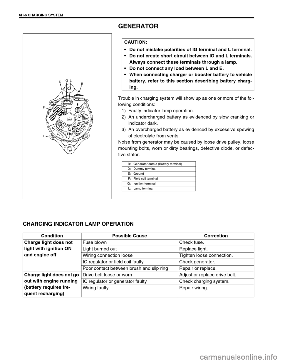
Trouble in charging system will show up as one or more of the fol-
lowing conditions:
1) Faulty indicator lamp operation.
2) An undercharged battery as evidenced by slow cranking or
indicator dark.
3) An overcharged battery as evidenced by excessive spewing
of electrolyte from vents.
Noise from generator may be caused by loose drive pulley, loose
mounting bolts, worn or dirty bearings, defective diode, or defec-
tive stator.
CHARGING INDICATOR LAMP OPERATION
CAUTION:
Do not mistake polarities of IG terminal and L terminal.
Do not create short circuit between IG and L terminals.
Always connect these terminals through a lamp.
Do not connect any load between L and E.
When connecting charger or booster battery to vehicle
battery, refer to this section describing battery charg-
ing.
B: Generator output (Battery terminal)
D: Dummy terminal
E: Ground
F: Field coil terminal
IG: Ignition terminal
L: Lamp terminal
Condition Possible Cause Correction
Charge light does not
light with ignition ON
and engine offFuse blown Check fuse.
Light burned out Replace light.
Wiring connection loose Tighten loose connection.
IC regulator or field coil faulty Check generator.
Poor contact between brush and slip ring Repair or replace.
Charge light does not go
out with engine running
(battery requires fre-
quent recharging)Drive belt loose or worn Adjust or replace drive belt.
IC regulator or generator faulty Check charging system.
Wiring faulty Repair wiring.
Page 687 of 698

CHARGING SYSTEM 6H-7
UNDERCHARGED BATTERY
This condition, as evidenced by slow cranking or indicator clear
with red dot can be caused by one or more of the following condi-
tions even though indicator lamp may be operating normal.
Following procedure also applies to cars with voltmeter and
ammeter.
Make sure that undercharged condition has not been caused
by accessories left on for extended period of time.
Check drive belt for proper tension.
If battery defect is suspected, refer to BATTERY section.
Inspect wiring for defects. Check all connections for tight-
ness and cleanliness, battery cable connections at battery,
starting motor and ignition ground cable.
NO-LOAD CHECK
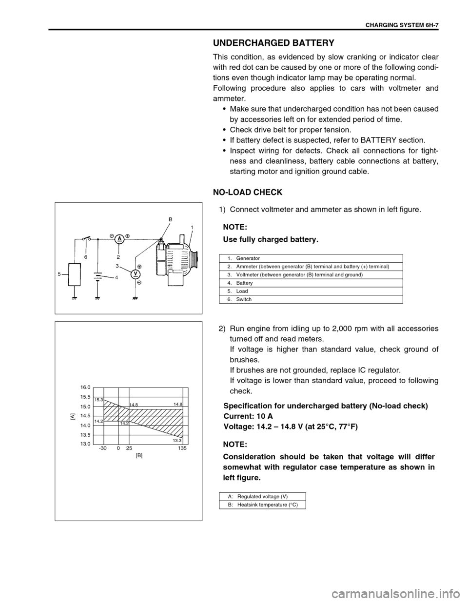
1) Connect voltmeter and ammeter as shown in left figure.
2) Run engine from idling up to 2,000 rpm with all accessories
turned off and read meters.
If voltage is higher than standard value, check ground of
brushes.
If brushes are not grounded, replace IC regulator.
If voltage is lower than standard value, proceed to following
check.
Specification for undercharged battery (No-load check)
Current: 10 A
Voltage: 14.2 – 14.8 V (at 25°C, 77°F) NOTE:
Use fully charged battery.
1. Generator
2. Ammeter (between generator (B) terminal and battery (+) terminal)
3. Voltmeter (between generator (B) terminal and ground)
4. Battery
5. Load
6. Switch
NOTE:
Consideration should be taken that voltage will differ
somewhat with regulator case temperature as shown in
left figure.
A: Regulated voltage (V)
B: Heatsink temperature (°C)
16.0
15.5
14.2 15.3
14.8
14.2
13.314.8
15.0
14.5
14.0
13.5
13.0
-30 0 25 135
[A]
[B]