Page 287 of 698

5-14 BRAKES
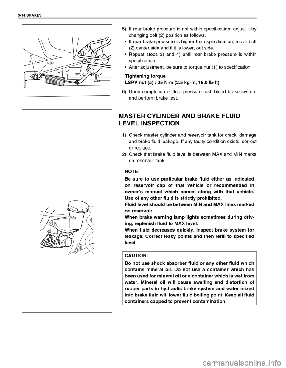
5) If rear brake pressure is not within specification, adjust it by
changing bolt (2) position as follows.
If rear brake pressure is higher than specification, move bolt
(2) center side and if it is lower, out side.
Repeat steps 3) and 4) until rear brake pressure is within
specification.
After adjustment, be sure to torque nut (1) to specification.
Tightening torque
LSPV nut (a) : 25 N·m (2.5 kg-m, 18.0 lb-ft)
6) Upon completion of fluid pressure test, bleed brake system
and perform brake test.
MASTER CYLINDER AND BRAKE FLUID
LEVEL INSPECTION
1) Check master cylinder and reservoir tank for crack, damage
and brake fluid leakage. If any faulty condition exists, correct
or replace.
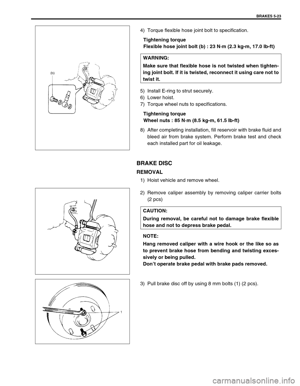
2) Check that brake fluid level is between MAX and MIN marks
on reservoir tank.
2
1, (a)
NOTE:
Be sure to use particular brake fluid either as indicated
on reservoir cap of that vehicle or recommended in
owner’s manual which comes along with that vehicle.
Use of any other fluid is strictly prohibited.
Fluid level should be between MIN and MAX lines marked
on reservoir.
When brake warning lamp lights sometimes during driv-
ing, replenish fluid to MAX level.
When fluid decreases quickly, inspect brake system for
leakage. Correct leaky points and then refill to specified
level.
CAUTION:
Do not use shock absorber fluid or any other fluid which
contains mineral oil. Do not use a container which has
been used for mineral oil or a container which is wet from
water. Mineral oil will cause swelling and distortion of
rubber parts in hydraulic brake system and water mixed
into brake fluid will lower fluid boiling point. Keep all fluid
containers capped to prevent contamination.
MAX
MIN
Page 288 of 698

BRAKES 5-15
BRAKE HOSE AND PIPE INSPECTION
HOSE
The brake hose assembly should be checked for road hazard
damage, for cracks and chafing of outer cover, for leaks and blis-
ters. A light and mirror may be needed for an adequate inspec-
tion. If any of above conditions are observed on brake hose, it is
necessary to replace it.
PIPE
Inspect the pipe for damage, cracks, dents and corrosion. If any
defect is found, replace it.
ON-VEHICLE SERVICE
AIR BLEEDING OF BRAKE SYSTEM
Bleeding operation is necessary to remove air whenever it
entered hydraulic brake system.
Hydraulic lines of brake system are based on the diagonal split
system. When a brake pipe or hose was disconnected at the
wheel, bleeding operation must be performed at both ends of the
line of the removed pipe or hose. When any joint part of the mas-
ter cylinder of other joint part between the master cylinder and
each brake (wheel) was removed, the hydraulic brake system
must be bled at all 4 wheel brakes.
CAUTION:
Brake fluid is extremely damaging to paint. If fluid should
accidentally touch painted surface, immediately wipe
fluid from paint and clean painted surface.
NOTE:
Perform bleeding operation starting with wheel cylinder
farthest from master cylinder and then at front caliper of
the same brake line. Do the same on the other brake line.
1. Right brake caliper 4. Left wheel cylinder
2. Left brake caliper A : FRONT
3. Right wheel cylinder B : REAR
Page 296 of 698

BRAKES 5-23
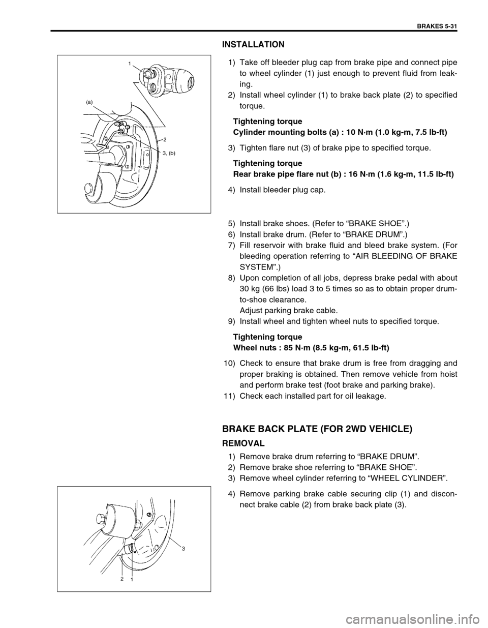
4) Torque flexible hose joint bolt to specification.
Tightening torque
Flexible hose joint bolt (b) : 23 N·m (2.3 kg-m, 17.0 Ib-ft)
5) Install E-ring to strut securely.
6) Lower hoist.
7) Torque wheel nuts to specifications.
Tightening torque
Wheel nuts : 85 N·m (8.5 kg-m, 61.5 Ib-ft)
8) After completing installation, fill reservoir with brake fluid and
bleed air from brake system. Perform brake test and check
each installed part for oil leakage.
BRAKE DISC
REMOVAL
1) Hoist vehicle and remove wheel.
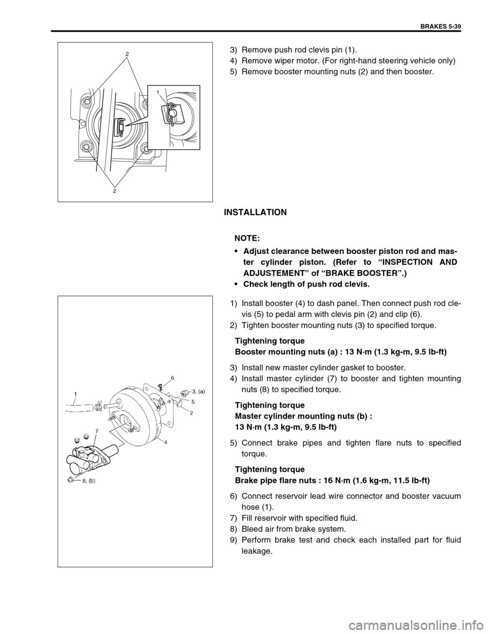
2) Remove caliper assembly by removing caliper carrier bolts
(2 pcs)
3) Pull brake disc off by using 8 mm bolts (1) (2 pcs).WARNING:
Make sure that flexible hose is not twisted when tighten-
ing joint bolt. If it is twisted, reconnect it using care not to
twist it.
CAUTION:
During removal, be careful not to damage brake flexible
hose and not to depress brake pedal.
NOTE:
Hang removed caliper with a wire hook or the like so as
to prevent brake hose from bending and twisting exces-
sively or being pulled.
Don’t operate brake pedal with brake pads removed.
Page 304 of 698

BRAKES 5-31
INSTALLATION
1) Take off bleeder plug cap from brake pipe and connect pipe
to wheel cylinder (1) just enough to prevent fluid from leak-
ing.
2) Install wheel cylinder (1) to brake back plate (2) to specified
torque.
Tightening torque
Cylinder mounting bolts (a) : 10 N·m (1.0 kg-m, 7.5 lb-ft)
3) Tighten flare nut (3) of brake pipe to specified torque.
Tightening torque
Rear brake pipe flare nut (b) : 16 N·m (1.6 kg-m, 11.5 lb-ft)
4) Install bleeder plug cap.
5) Install brake shoes. (Refer to “BRAKE SHOE”.)
6) Install brake drum. (Refer to “BRAKE DRUM”.)
7) Fill reservoir with brake fluid and bleed brake system. (For
bleeding operation referring to “AIR BLEEDING OF BRAKE
SYSTEM”.)
8) Upon completion of all jobs, depress brake pedal with about
30 kg (66 lbs) load 3 to 5 times so as to obtain proper drum-
to-shoe clearance.
Adjust parking brake cable.
9) Install wheel and tighten wheel nuts to specified torque.
Tightening torque
Wheel nuts : 85 N·m (8.5 kg-m, 61.5 lb-ft)
10) Check to ensure that brake drum is free from dragging and
proper braking is obtained. Then remove vehicle from hoist
and perform brake test (foot brake and parking brake).
11) Check each installed part for oil leakage.
BRAKE BACK PLATE (FOR 2WD VEHICLE)
REMOVAL
1) Remove brake drum referring to “BRAKE DRUM”.
2) Remove brake shoe referring to “BRAKE SHOE”.
3) Remove wheel cylinder referring to “WHEEL CYLINDER”.
4) Remove parking brake cable securing clip (1) and discon-
nect brake cable (2) from brake back plate (3).
Page 312 of 698

BRAKES 5-39
3) Remove push rod clevis pin (1).
4) Remove wiper motor. (For right-hand steering vehicle only)
5) Remove booster mounting nuts (2) and then booster.
INSTALLATION
1) Install booster (4) to dash panel. Then connect push rod cle-
vis (5) to pedal arm with clevis pin (2) and clip (6).
2) Tighten booster mounting nuts (3) to specified torque.
Tightening torque
Booster mounting nuts (a) : 13 N·m (1.3 kg-m, 9.5 lb-ft)
3) Install new master cylinder gasket to booster.
4) Install master cylinder (7) to booster and tighten mounting
nuts (8) to specified torque.
Tightening torque
Master cylinder mounting nuts (b) :
13 N·m (1.3 kg-m, 9.5 lb-ft)
5) Connect brake pipes and tighten flare nuts to specified
torque.
Tightening torque
Brake pipe flare nuts : 16 N·m (1.6 kg-m, 11.5 lb-ft)
6) Connect reservoir lead wire connector and booster vacuum
hose (1).
7) Fill reservoir with specified fluid.
8) Bleed air from brake system.
9) Perform brake test and check each installed part for fluid
leakage.
1
2
2
NOTE:
Adjust clearance between booster piston rod and mas-
ter cylinder piston. (Refer to “INSPECTION AND
ADJUSTEMENT” of “BRAKE BOOSTER”.)
Check length of push rod clevis.
Page 314 of 698
BRAKES 5-41
BRAKE HOSE/PIPE
FRONT BRAKE HOSE/PIPE
REMOVAL
1) Raise and support vehicle properly. Remove tire and wheel.
2) Clean dirt and foreign material from both flexible hose end and pipe end fittings.
3) Remove brake flexible hose or pipe.
INSTALLATION
Reverse brake flexible hose installation procedure, noting the followings.
Make sure that steering wheel is in straight-forward position and flexible hose has not twist or kink.
Check to make sure that flexible hose doesn’t contact any part of suspension, both in extreme right and
extreme left turn conditions. If it does at any point, remove and correct. Fill and maintain brake fluid level in
reservoir.
Bleed brake system. Refer to “AIR BLEEDING OF BRAKE SYSTEM”.
Perform brake test and check installed part for fluid leakage. NOTE:
This operation is not necessary when removing pipes connecting master cylinder.
Page 317 of 698
5-44 BRAKES
REAR BRAKE HOSE/PIPE
REMOVAL
1) Raise and support vehicle properly. Remove tire and wheel.
2) Clean dirt and foreign material from both flexible hose end and pipe end fittings.
3) Remove brake flexible hose or pipe.
INSTALLATION
Reverse brake flexible hose installation procedure, nothing the followings.
Fill and maintain brake fluid level in reservoir.
Bleed brake system. Refer to “AIR BLEEDING OF BRAKE SYSTEM”.
Perform brake test and check each installed part for fluid leakage.
Never reuse protector nut once removed. Be sure to use a new one.
Install clamps properly referring to figure below and tighten bolts.
When installing hose, make sure that it has no twist or kink.
Page 319 of 698
5-46 BRAKES
PARKING BRAKE CABLE
REMOVAL
1) Raise, suitably support vehicle and remove wheel.
2) Remove parking brake cable.
INSTALLATION
Install it by reversing removal procedure, noting the following points.
Install clamps properly referring to figure below.
Tighten bolts and nuts to specified torque.
Adjust parking brake cable. (Refer to “PARKING BRAKE INSPECTION AND ADJUSTMENT”.)
Check brake drum for dragging and brake system for proper performance. After removing vehicle from hoist,
brake test should be performed.