2000 SUZUKI SWIFT brake system
[x] Cancel search: brake systemPage 49 of 698

0B-20 MAINTENANCE AND LUBRICATION
ENGINE START
Check engine start for readiness.
On automatic transmission vehicles, try to start the engine in each select lever position. The starting motor
should crank only in “P” (Park) or “N” (Neutral).
On manual transmission vehicles, place the shift lever in “Neutral,” depress clutch pedal fully any try to start.
EXHAUST SYSTEM CHECK
Check for leakage, cracks or loose supports.
CLUTCH (FOR MANUAL TRANSMISSION)
Check for the following.
Clutch is completely released when depressing clutch pedal,
No slipping clutch occurs when releasing pedal and accelerating.
Clutch itself is free from any abnormal condition.
GEARSHIFT OR SELECT LEVER (TRANSMISSION)
Check gear shift or select lever for smooth shifting to all positions and for good performance of transmission in
any position.
With automatic transmission equipped vehicle, also check that shift indicator indicates properly according to
which position select lever is shifted to.
With automatic transmission equipped vehicle, make sure that vehicle is at complete stop when shifting select
lever to “P” range position and release all brakes.
BRAKE
Foot Brake
Check the followings:
that brake pedal has proper travel,
that brake works properly,
that it is free from noise,
that vehicle does not pull to one side when brake is applied.
and that brake do not drag.
Parking Brake
Check that lever has proper travel.
Check to ensure that parking brake is fully effective when the vehicle is stopped on the safe slope and brake
lever is pulled all the way.WARNING:
Before performing the following check, be sure to have enough room around the vehicle. Then, firmly
apply both the parking brake and the regular brakes. Do not use the accelerator pedal. If the engine
starts, be ready to turn off the ignition promptly. Take these precautions because the vehicle could
move without warning and possibly cause personal injury or property damage.
WARNING:
With vehicle parked on a fairly steep slope, make sure nothing is in the way downhill to avoid any per-
sonal injury or property damage. Be prepared to apply regular brake quickly even if vehicle should
start to move.
Page 50 of 698

MAINTENANCE AND LUBRICATION 0B-21
STEERING
Check to ensure that steering wheel is free from instability, or abnormally heavy feeling.
Check that the vehicle does not wander or pull to one side.
ENGINE
Check that engine responds readily at all speeds.
Check that engine is free from abnormal noise and abnormal vibration.
BODY, WHEELS AND POWER TRANSMITTING SYSTEM
Check that body, wheels and power transmitting system are free from abnormal noise and abnormal vibration or
any other abnormal condition.
METERS AND GAUGE
Check that speedometer, odometer, fuel meter, temperature gauge, etc. are operating accurately.
LIGHTS
Check that all lights operate properly.
WINDSHIELD DEFROSTER
Periodically check that air comes out from defroster outlet when operating heater or air conditioning.
Set mode control lever to defroster position and fan switch lever to “HI” position for this check.
RECOMMENDED FLUIDS AND LUBRICANTS
Engine oil SE, SF, SG, SH or SJ grade (Refer to “ENGINE OIL AND OIL FILTER”
in this section for engine oil viscosity.)
Engine coolant
(Ethylene glycol base coolant)“Antifreeze/Anticorrosion coolant”
Brake fluid DOT 3
Manual transmission oil Refer to “M/T OIL CHANGE” in Section 7A.
Transfer oil (4WD) Refer to “TRANSFER OIL CHANGE” in Section 7D.
Differential oil (4WD) Refer to “DIFFERENTIAL OIL CHANGE” in Section 7F.
Automatic transmission fluid
An equivalent of DEXRON
®-III
Door hinges Engine oil or water resistance chassis grease
Hood latch assembly Engine oil or water resistance chassis grease
Key lock cylinder Spray lubricant
Page 111 of 698

3-2 STEERING, SUSPENSION, WHEELS AND TIRES
DIAGNOSIS
GENERAL DIAGNOSIS
Since the problems in steering, suspension, wheels and tires involve several systems, they must all be consid-
ered when diagnosing a complaint. To avoid using the wrong symptom, always road test the vehicle first. Pro-
ceed with the following preliminary inspection and correct any defects which are found.
1) Inspect tires for proper pressure and uneven wear.
2) Raise vehicle on a hoist and inspect front and rear suspension and steering system for loose or damaged
parts.
3) Spin front wheels. Inspect for out-of-round tires, out-of-balance tires, bent rims, loosen and/or rough wheel
bearings.
DIAGNOSIS TABLE
Condition Possible Cause Correction
Vehicle Pulls (Leads)
Mismatched or uneven tires Replace tire.
Tires not adequately inflated Adjust tire pressure.
Broken or sagging springs Replace spring.
Radial tire lateral force Replace tire.
Disturbed front end alignment Check and adjust front end align-
ment.
Brake dragging in one road wheel Repair brake.
Loose, bent or broken front or rear suspension
partsTighten or replace suspension
parts.
Abnormal or
Excessive Tire WearSagging or broken spring Replace spring.
Tire out of balance Adjust balance or replace tire.
Disturbed front end alignment Check and adjust front end align-
ment.
Faulty strut (shock absorber) Replace strut.
Hard driving Replace tire.
Overloaded vehicle Replace tire.
Not rotating tire Replace or rotate tire.
Worn or loose wheel bearing Replace wheel bearing.
Wobbly wheel or tire Replace wheel or tire.
Tires not adequately inflated Adjust tire pressure.
Wheel Tramp
Blister or bump on tire Replace tire.
Improper strut (shock absorber) action Replace strut.
Shimmy, Shake or
VibrationTire or wheel out of balance Balance wheels or replace tire and/
or wheel.
Loosen wheel bearings Replace wheel bearing.
Worn tie rod ends Replace tie rod end.
Worn lower ball joints Replace front suspension arm.
Excessive wheel runout Repair or replace wheel and/or tire.
Blister or bump on tire Replace tire.
Excessively loaded radial runout of tire/wheel
assemblyReplace tire or wheel.
Disturbed front end alignment Check and adjust front end align-
ment.
Loose or worn steering linkage Tighten or replace steering linkage.
Loose steering gear case bolts Tighten case bolts.
Page 149 of 698

3B1-8 ELECTRICAL POWER STEERING (P/S) SYSTEM
DTC CHECK
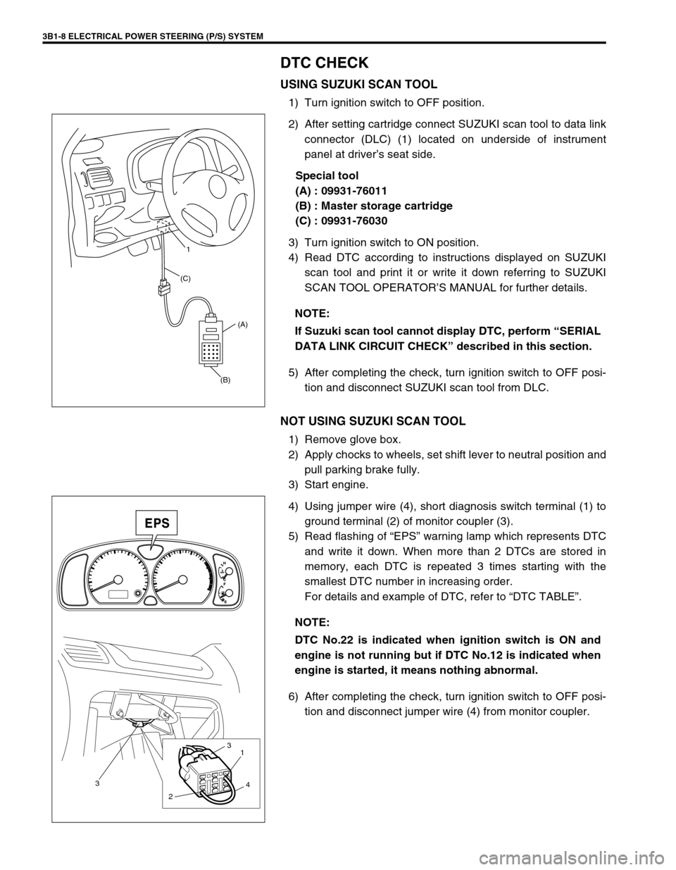
USING SUZUKI SCAN TOOL
1) Turn ignition switch to OFF position.
2) After setting cartridge connect SUZUKI scan tool to data link
connector (DLC) (1) located on underside of instrument
panel at driver’s seat side.
Special tool
(A) : 09931-76011
(B) : Master storage cartridge
(C) : 09931-76030
3) Turn ignition switch to ON position.
4) Read DTC according to instructions displayed on SUZUKI
scan tool and print it or write it down referring to SUZUKI
SCAN TOOL OPERATOR’S MANUAL for further details.
5) After completing the check, turn ignition switch to OFF posi-
tion and disconnect SUZUKI scan tool from DLC.
NOT USING SUZUKI SCAN TOOL
1) Remove glove box.
2) Apply chocks to wheels, set shift lever to neutral position and
pull parking brake fully.
3) Start engine.
4) Using jumper wire (4), short diagnosis switch terminal (1) to
ground terminal (2) of monitor coupler (3).
5) Read flashing of “EPS” warning lamp which represents DTC
and write it down. When more than 2 DTCs are stored in
memory, each DTC is repeated 3 times starting with the
smallest DTC number in increasing order.
For details and example of DTC, refer to “DTC TABLE”.
6) After completing the check, turn ignition switch to OFF posi-
tion and disconnect jumper wire (4) from monitor coupler. NOTE:
If Suzuki scan tool cannot display DTC, perform “SERIAL
DATA LINK CIRCUIT CHECK” described in this section.
(B)(A) (C)1
NOTE:
DTC No.22 is indicated when ignition switch is ON and
engine is not running but if DTC No.12 is indicated when
engine is started, it means nothing abnormal.
3
21
3
4
Page 155 of 698

3B1-14 ELECTRICAL POWER STEERING (P/S) SYSTEM
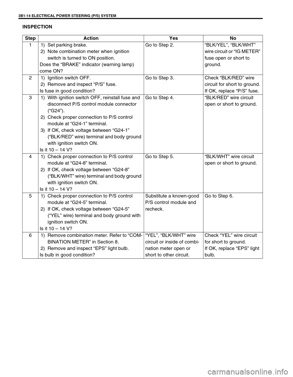
INSPECTION
Step Action Yes No
1 1) Set parking brake.
2) Note combination meter when ignition
switch is turned to ON position.
Does the “BRAKE” indicator (warning lamp)
come ON?Go to Step 2.“BLK/YEL”, “BLK/WHT”
wire circuit or “IG METER”
fuse open or short to
ground.
2 1) Ignition switch OFF.
2) Remove and inspect “P/S” fuse.
Is fuse in good condition?Go to Step 3. Check “BLK/RED” wire
circuit for short to ground.
If OK, replace “P/S” fuse.
3 1) With ignition switch OFF, reinstall fuse and
disconnect P/S control module connector
(“G24”).
2) Check proper connection to P/S control
module at “G24-1” terminal.
3) If OK, check voltage between “G24-1”
(“BLK/RED” wire) terminal and body ground
with ignition switch ON.
Is it 10 – 14 V?Go to Step 4.“BLK/RED” wire circuit
open or short to ground.
4 1) Check proper connection to P/S control
module at “G24-8” terminal.
2) If OK, check voltage between “G24-8”
(“BLK/WHT” wire) terminal and body ground
with ignition switch ON.
Is it 10 – 14 V?Go to Step 5.“BLK/WHT” wire circuit
open or short to ground.
5 1) Check proper connection to P/S control
module at “G24-5” terminal.
2) If OK, check voltage between “G24-5”
(“YEL” wire) terminal and body ground with
ignition switch ON.
Is it 10 – 14 V?Substitute a known-good
P/S control module and
recheck.Go to Step 6.
6 1) Remove combination meter. Refer to “COM-
BINATION METER” in Section 8.
2) Remove and inspect “EPS” light bulb.
Is bulb in good condition?“YEL”, “BLK/WHT” wire
circuit or inside of combi-
nation meter open or
short to other circuit.Check “YEL” wire circuit
for short to ground.
If OK, replace “EPS” light
bulb.
Page 231 of 698

3E-18 REAR SUSPENSION
8) Install wheel speed sensor and clamp wire securely (right &
left) (if equipped with ABS).
9) Install LSPV spring (1) to rear axle (2).
Tighten nut (3) temporarily at this step (if equipped with
LSPV).
10) Connect brake pipes (1) (right & left) to wheel cylinders (2)
and tighten brake pipe flare nuts (3) to specified torque.
Tightening torque
Brake pipe flare nuts (a) : 16 N·m (1.6 kg-m, 11.5 lb-ft)
11) Connect brake flexible hoses (1) to bracket on rear axle and
secure it with E-rings (2).
12) Install brake drums (right & left). Refer to “BRAKE DRUM” in
Section 5.
13) Fill reservoir with brake fluid and bleed brake system (For
bleeding operation, refer to Section 5.)
14) Install wheel and tighten wheel nuts (1) to specified torque.
Tightening torque
Wheel nuts (a) : 85 N·m (8.5 kg-m, 61.5 lb-ft)
231
Page 238 of 698

REAR SUSPENSION 3E-25
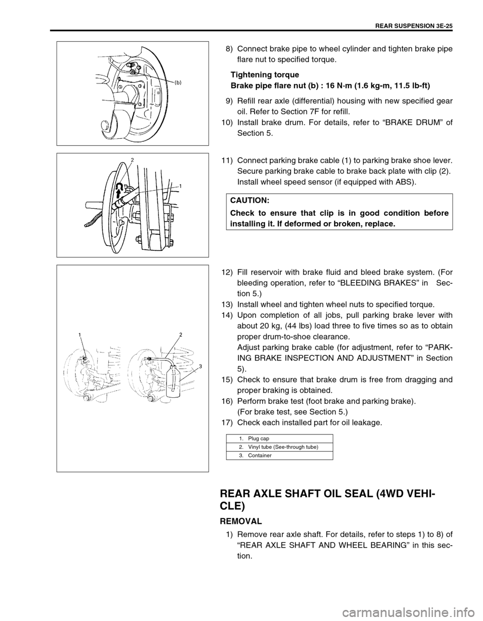
8) Connect brake pipe to wheel cylinder and tighten brake pipe
flare nut to specified torque.
Tightening torque
Brake pipe flare nut (b) : 16 N·m (1.6 kg-m, 11.5 lb-ft)
9) Refill rear axle (differential) housing with new specified gear
oil. Refer to Section 7F for refill.
10) Install brake drum. For details, refer to “BRAKE DRUM” of
Section 5.
11) Connect parking brake cable (1) to parking brake shoe lever.
Secure parking brake cable to brake back plate with clip (2).
Install wheel speed sensor (if equipped with ABS).
12) Fill reservoir with brake fluid and bleed brake system. (For
bleeding operation, refer to “BLEEDING BRAKES” in Sec-
tion 5.)
13) Install wheel and tighten wheel nuts to specified torque.
14) Upon completion of all jobs, pull parking brake lever with
about 20 kg, (44 lbs) load three to five times so as to obtain
proper drum-to-shoe clearance.
Adjust parking brake cable (for adjustment, refer to “PARK-
ING BRAKE INSPECTION AND ADJUSTMENT” in Section
5).
15) Check to ensure that brake drum is free from dragging and
proper braking is obtained.
16) Perform brake test (foot brake and parking brake).
(For brake test, see Section 5.)
17) Check each installed part for oil leakage.
REAR AXLE SHAFT OIL SEAL (4WD VEHI-
CLE)
REMOVAL
1) Remove rear axle shaft. For details, refer to steps 1) to 8) of
“REAR AXLE SHAFT AND WHEEL BEARING” in this sec-
tion.
CAUTION:
Check to ensure that clip is in good condition before
installing it. If deformed or broken, replace.
1. Plug cap
2. Vinyl tube (See-through tube)
3. Container
Page 243 of 698

3E-30 REAR SUSPENSION
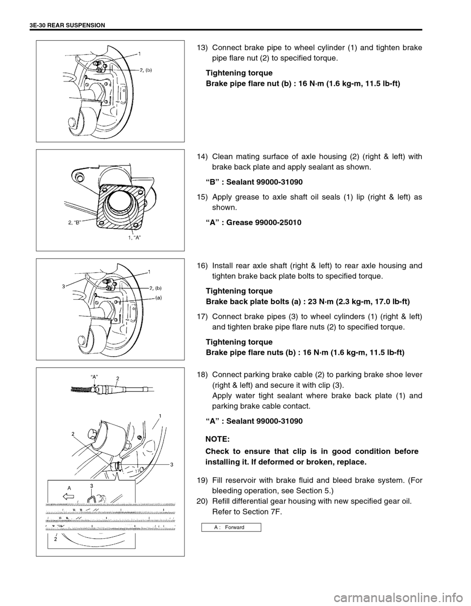
13) Connect brake pipe to wheel cylinder (1) and tighten brake
pipe flare nut (2) to specified torque.
Tightening torque
Brake pipe flare nut (b) : 16 N·m (1.6 kg-m, 11.5 lb-ft)
14) Clean mating surface of axle housing (2) (right & left) with
brake back plate and apply sealant as shown.
“B” : Sealant 99000-31090
15) Apply grease to axle shaft oil seals (1) lip (right & left) as
shown.
“A” : Grease 99000-25010
16) Install rear axle shaft (right & left) to rear axle housing and
tighten brake back plate bolts to specified torque.
Tightening torque
Brake back plate bolts (a) : 23 N·m (2.3 kg-m, 17.0 lb-ft)
17) Connect brake pipes (3) to wheel cylinders (1) (right & left)
and tighten brake pipe flare nuts (2) to specified torque.
Tightening torque
Brake pipe flare nuts (b) : 16 N·m (1.6 kg-m, 11.5 lb-ft)
18) Connect parking brake cable (2) to parking brake shoe lever
(right & left) and secure it with clip (3).
Apply water tight sealant where brake back plate (1) and
parking brake cable contact.
“A” : Sealant 99000-31090
19) Fill reservoir with brake fluid and bleed brake system. (For
bleeding operation, see Section 5.)
20) Refill differential gear housing with new specified gear oil.
Refer to Section 7F.
NOTE:
Check to ensure that clip is in good condition before
installing it. If deformed or broken, replace.
A : Forward