Page 239 of 698

3E-26 REAR SUSPENSION
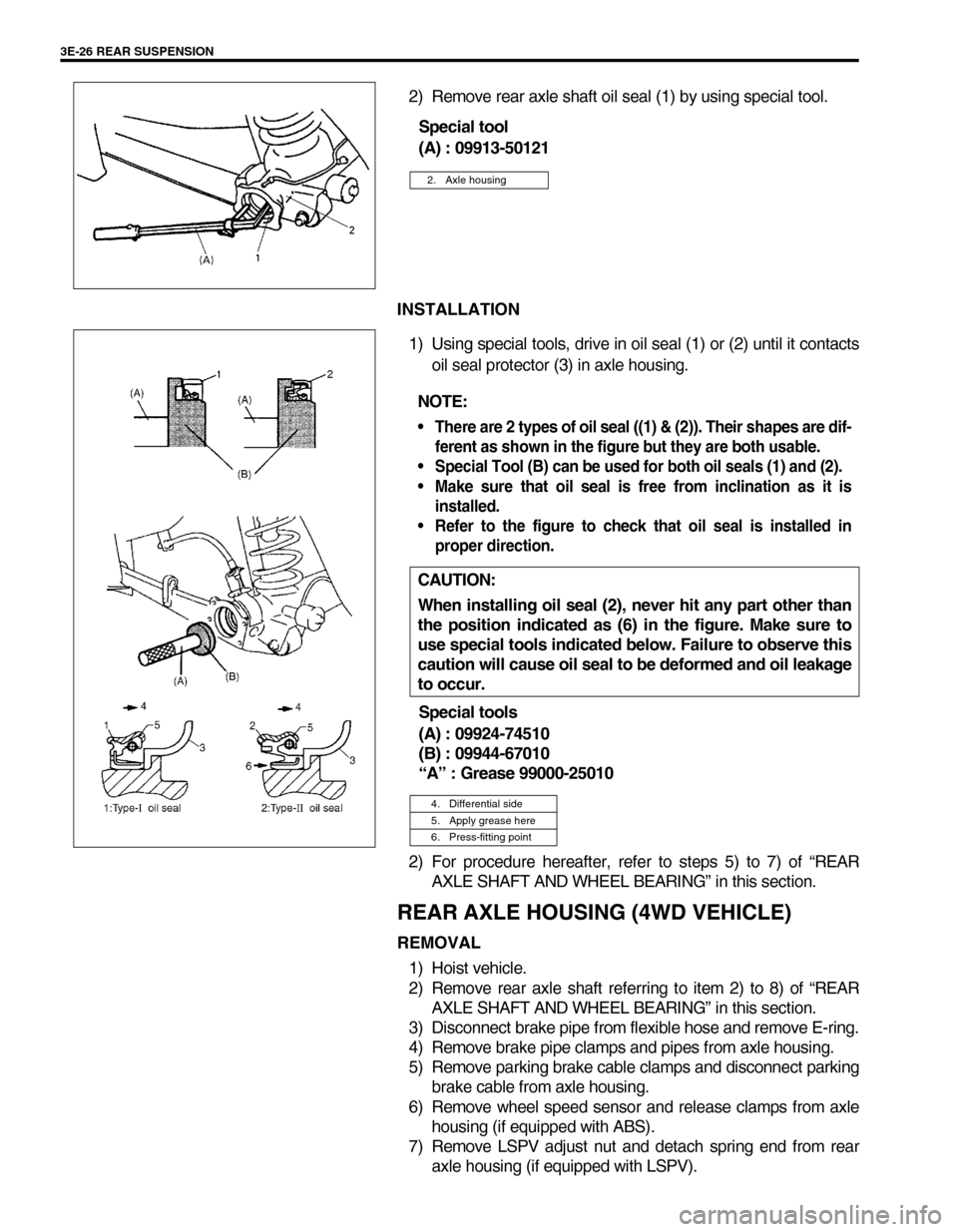
2) Remove rear axle shaft oil seal (1) by using special tool.
Special tool
(A) : 09913-50121
INSTALLATION
1) Using special tools, drive in oil seal (1) or (2) until it contacts
oil seal protector (3) in axle housing.
Special tools
(A) : 09924-74510
(B) : 09944-67010
“A” : Grease 99000-25010
2) For procedure hereafter, refer to steps 5) to 7) of “REAR
AXLE SHAFT AND WHEEL BEARING” in this section.
REAR AXLE HOUSING (4WD VEHICLE)
REMOVAL
1) Hoist vehicle.
2) Remove rear axle shaft referring to item 2) to 8) of “REAR
AXLE SHAFT AND WHEEL BEARING” in this section.
3) Disconnect brake pipe from flexible hose and remove E-ring.
4) Remove brake pipe clamps and pipes from axle housing.
5) Remove parking brake cable clamps and disconnect parking
brake cable from axle housing.
6) Remove wheel speed sensor and release clamps from axle
housing (if equipped with ABS).
7) Remove LSPV adjust nut and detach spring end from rear
axle housing (if equipped with LSPV).
2. Axle housing
NOTE:
There are 2 types of oil seal ((1) & (2)). Their shapes are dif-
ferent as shown in the figure but they are both usable.
Special Tool (B) can be used for both oil seals (1) and (2).
Make sure that oil seal is free from inclination as it is
installed.
Refer to the figure to check that oil seal is installed in
proper direction.
CAUTION:
When installing oil seal (2), never hit any part other than
the position indicated as (6) in the figure. Make sure to
use special tools indicated below. Failure to observe this
caution will cause oil seal to be deformed and oil leakage
to occur.
4. Differential side
5. Apply grease here
6. Press-fitting point
Page 247 of 698

3F-2 WHEELS AND TIRES
GENERAL DESCRIPTION
TIRES
This vehicle is equipped with the following tire.
Tire size
: 165/70R14
The tire is of tubeless type. The tire is designed to operate satisfactorily with loads up to the full rated load
capacity when inflated to the recommended inflation pressures.
Correct tire pressures and driving habits have an important influence on tire life. Heavy cornering, excessively
rapid acceleration, and unnecessary sharp braking increase tire wear.
WHEELS
Standard equipment wheels are the following steel wheel.
Wheel size
: 14 x 4 1/2 J
REPLACEMENT TIRES
When replacement is necessary, the original equipment type tire should be used. Refer to the “Tire Placard”.
Replacement tires should be of the same size, load range and construction as those originally on the vehicle.
Use of any other size or type tire may affect ride, handling, speedometer/odometer calibration, vehicle ground
clearance and tire or snow chain clearance to the body and chassis.
It is recommended that new tires be installed in pairs on the same axle. If necessary to replace only one tire, it
should be paired with the tire having the most tread, to equalize braking traction.
The metric term for tire inflation pressure is the kilo pascal (kPa).
Tire pressures is usually printed in both kPa and psi on the “Tire
Placard”.
Metric tire gauges are available from tool suppliers.
The chart, shown the table, converts commonly used inflation
pressures from kPa to psi.
REPLACEMENT WHEELS
Wheels must be replaced if they are bent, dented, have excessive lateral or radial runout, air leak through
welds, have elongated bolt holes, if lug nuts won’t stay tight, or if they are heavily rusted. Wheels with greater
runout than shown in figure below may cause objectional vibrations.
Replacement wheels must be equivalent to the original equipment wheels in load capacity, diameter, rim with
offset and mounting configuration. A wheel of improper size or type may affect wheel and bearing life, brake
cooling, speedometer/odometer calibration, vehicle ground clearance and tire clearance to body and chassis.WARNING:
Do not mix different types of tires on the same vehicle such as radial, bias and bias-belted tires except
in emergencies, because handling may be seriously affected and may result in loss of control.
kPa kgf/cm²pis
160 1.6 23
180 1.8 26
200 2.0 29
220 2.2 32
240 2.4 35
260 2.6 38
280 2.8 41
300 3.0 44
Page 252 of 698
WHEELS AND TIRES 3F-7
ON-VEHICLE SERVICE
WHEEL
REMOVAL
1) Loosen wheel nuts by approximately 180° (half a rotation).
2) Hoist vehicle.
3) Remove wheel.
INSTALLATION
For installation, reverse removal procedure, noting the followings.
Wheel nuts must be tightened in sequence and to proper
torque to avoid bending wheel or brake disc.
Tightening order
: “A”-“B”-“C”-“D”
Tightening torque
Wheel nut (a) : 85 N·m (8.5 kg-m, 61.5 lb-ft) CAUTION:
Never use heat to loosen tight wheel because application
of heat to wheel can shorten life of wheel and damage
wheel bearings.
NOTE:
Before installing wheels, remove any build-up of corro-
sion on wheel mounting surface and brake disc mount-
ing surface by scraping and wire brushing. Installing
wheels without good metal-to-metal contact at mounting
surfaces can cause wheel nuts to loosen, which can later
allow a wheel to come off while vehicle is moving.
Page 255 of 698
4A-2 FRONT DRIVE SHAFT
GENERAL DESCRIPTION
COMPONENT
A constant velocity ball joint is used on the wheel side of front drive shaft. For right side drive shaft of 2WD vehi-
cle, a constant velocity tripod joint on the differential side. For left side drive shaft of every type vehicles and
right side drive shaft of 4WD vehicle, a constant velocity double offset joint is used on the differential or transfer
side. The drive shaft can slide through the tripod joint or the double offset joint in the extension/contraction direc-
tion.
DIAGNOSIS
DIAGNOSIS TABLE
DRIVE SHAFT BOOT CHECK
Inspect drive shaft boot for tear.
If even a small tear is noted, replace with new one. Condition Possible Cause Correction
Abnormal Noise
Worn or breakage drive shaft joint Replace.
Worn or breakage center bearing Replace.
Page 256 of 698

FRONT DRIVE SHAFT 4A-3
ON-VEHICLE SERVICE
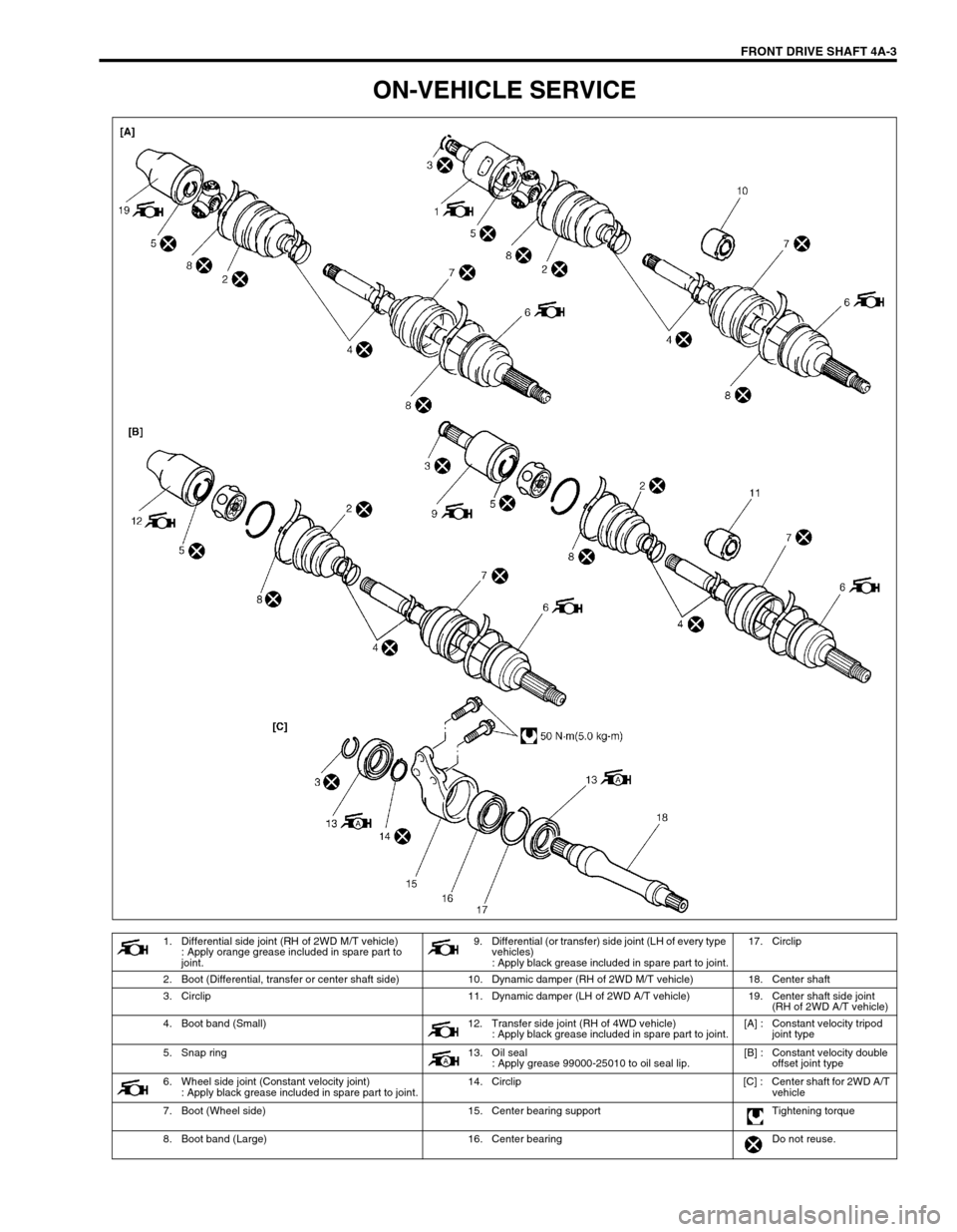
1. Differential side joint (RH of 2WD M/T vehicle)
: Apply orange grease included in spare part to
joint.9. Differential (or transfer) side joint (LH of every type
vehicles)
: Apply black grease included in spare part to joint.17. Circlip
2. Boot (Differential, transfer or center shaft side) 10. Dynamic damper (RH of 2WD M/T vehicle) 18. Center shaft
3. Circlip 11. Dynamic damper (LH of 2WD A/T vehicle) 19. Center shaft side joint
(RH of 2WD A/T vehicle)
4. Boot band (Small) 12. Transfer side joint (RH of 4WD vehicle)
: Apply black grease included in spare part to joint.[A] : Constant velocity tripod
joint type
5. Snap ring 13. Oil seal
: Apply grease 99000-25010 to oil seal lip.[B] : Constant velocity double
offset joint type
6. Wheel side joint (Constant velocity joint)
: Apply black grease included in spare part to joint.14. Circlip [C] : Center shaft for 2WD A/T
vehicle
7. Boot (Wheel side) 15. Center bearing support Tightening torque
8. Boot band (Large) 16. Center bearing Do not reuse.
Page 260 of 698
FRONT DRIVE SHAFT 4A-7
4) Draw away cage (1) by using bearing puller (2), and remove
boot (3) from shaft.
5) Remove boot band, then pull out differential side boot from
shaft.
6) Pull out damper through shaft. (if equipped)
7) Undo boot bands of wheel side joint boot, then pull out boot
through shaft.
For Center Shaft and Center Bearing Support
1) Remove right side oil seal from center bearing support (1).
2) Remove circlip by using special tool.
Special tool
(A) : 09900-06108
3) Using hydraulic press (1), draw out center shaft (2) from cen-
ter bearing.
4) Remove left side oil seal from center bearing support (3).
CAUTION:
Do not disassemble wheel side joint. If any malcondition
is found in any joint, replace it as assembly.
Page 261 of 698

4A-8 FRONT DRIVE SHAFT
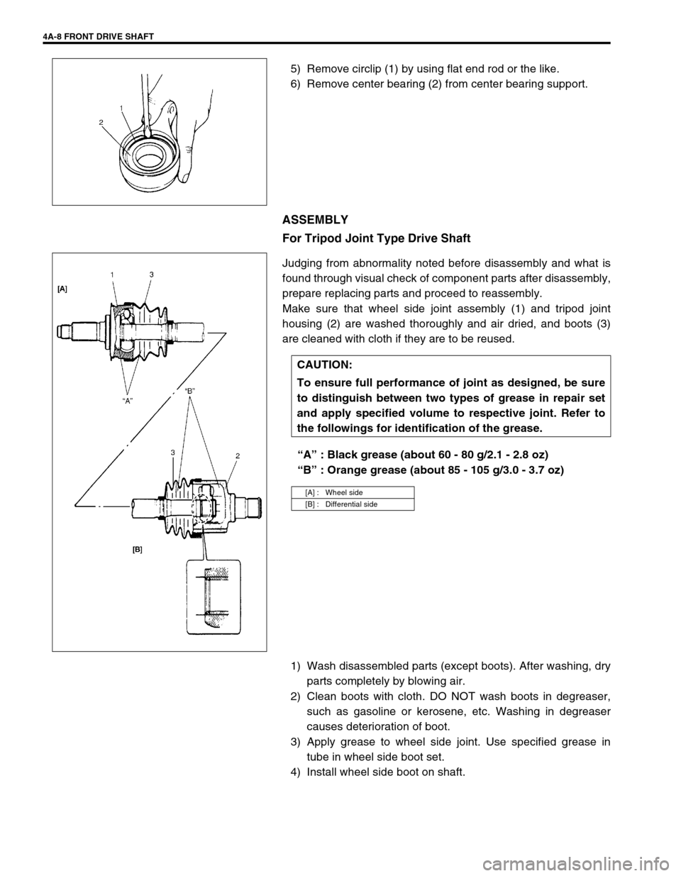
5) Remove circlip (1) by using flat end rod or the like.
6) Remove center bearing (2) from center bearing support.
ASSEMBLY
For Tripod Joint Type Drive Shaft
Judging from abnormality noted before disassembly and what is
found through visual check of component parts after disassembly,
prepare replacing parts and proceed to reassembly.
Make sure that wheel side joint assembly (1) and tripod joint
housing (2) are washed thoroughly and air dried, and boots (3)
are cleaned with cloth if they are to be reused.
“A” : Black grease (about 60 - 80 g/2.1 - 2.8 oz)
“B” : Orange grease (about 85 - 105 g/3.0 - 3.7 oz)
1) Wash disassembled parts (except boots). After washing, dry
parts completely by blowing air.
2) Clean boots with cloth. DO NOT wash boots in degreaser,
such as gasoline or kerosene, etc. Washing in degreaser
causes deterioration of boot.
3) Apply grease to wheel side joint. Use specified grease in
tube in wheel side boot set.
4) Install wheel side boot on shaft.
CAUTION:
To ensure full performance of joint as designed, be sure
to distinguish between two types of grease in repair set
and apply specified volume to respective joint. Refer to
the followings for identification of the grease.
[A] : Wheel side
[B] : Differential side
Page 267 of 698
4A-14 FRONT DRIVE SHAFT
When installing right oil seal (1), use care so that oil seal in
proper direction as shown figure.
Be sure apply grease to oil seal lip and bearing side space
indicated in figure.
“A” : Grease 99000-25010
INSTALLATION
Install drive shaft assembly by reversing removal procedure and
noting following points.
Clean front wheel bearing oil seal (1) and then apply grease.
Replace it if required.
“A” : Grease 99000-25010
CAUTION:
To avoid excessive expansion of boot and consequen-
tial disconnection of joint in boot, do not pull differen-
tial side joint housing.
Protect oil seals and boots from any damage, prevent-
ing them from unnecessary contact while installing
drive shaft.
Do not hit joint boot with hammer. Inserting joint only
by hands is allowed.
Make sure that differential side joint is inserted fully
and its snap ring is seated as it was.