2000 SUZUKI SWIFT turn signal
[x] Cancel search: turn signalPage 483 of 698

6-114 ENGINE GENERAL INFORMATION AND DIAGNOSIS
DTC P1717 A/T DRIVE RANGE (PARK/NEUTRAL POSITION) SIGNAL CIRCUIT
MALFUNCTION
WIRING DIAGRAM / CIRCUIT DESCRIPTION
DTC CONFIRMATION PROCEDURE
1) Turn ignition switch OFF.
2) Clear DTC with ignition switch ON.
3) Start engine and shift selector lever to “D” range.
4) Increase vehicle speed to higher than 20 mph, 32 km/h and then stop vehicle.
5) Repeat above step 4) 9 times.
6) Shift selector lever to “2” range and repeat above step 4) and 5).
7) Shift selector lever to “L” range and repeat above step 4) and 5).
8) Check DTC in “DTC” mode and pending DTC in “ON BOARD TEST” or “PENDING DTC” mode.
1. From ignition switch 2. Transmission range switch
[A] : Case of TYPE A is shown (See NOTE) [B] : Case of TYPE B is shown (See NOTE)
TCMECMIG1
12V P
R
N
D
2
L
C42 (31P) C41 (24P) G02 (17P)1 2 3 4 5 6 7 8 9
10 11 12 13 14 15 16 17 18 19 20 21
22 23 24 25 26 28 27 29 30 315 6
1 2 3 4 5 6 7
11 12
9 10 11 13 12 14 15 16
16 171 2
7 8
13 14 3 4
9 10
15 17 188
19 20 21 22 23 24
IG11
C44-8
REDGRN/ORN1
2G02-6 [B] C41-14 [A]
C41-15 [A]
G02-2 [B] GRN RED [B]LT BLU [A]
NOTE:
For TYPE A and TYPE B, refer to NOTE in “ECM VOLTAGE VALUES TABLE” for applicable model.
DTC DETECTING CONDITION POSSIBLE CAUSE
“D” range signal not inputted (Park/Neutral position
signal inputted) to ECM while vehicle running
✱2 driving cycle detection logic, continuous monitor-
ing.“LT BLU” circuit open
Transmission range switch malfunction
“R”, “D”, “2” or “L” range signal circuit open
TCM power or ground circuit open
TCM malfunction
ECM malfunction
WARNING:
When performing a road test, select a place where there is no traffic or possibility of a traffic acci-
dent and be very careful during testing to avoid occurrence of an accident.
Road test should be carried out with 2 persons, a driver and a tester.
Page 484 of 698

ENGINE GENERAL INFORMATION AND DIAGNOSIS 6-115
INSPECTION
Fig. 1 for Step 3Step Action Yes No
1Was “ENGINE DIAG. FLOW TABLE” per-
formed?Go to Step 2. Go to “ENGINE DIAG.
FLOW TABLE”.
2 Is SUZUKI scan tool available? Go to Step 3. Go to Step 4.
3 Check PNP Signal (“D” range signal).
1) Connect SUZUKI scan tool to DLC with igni-
tion switch OFF. See Fig. 1.
2) Turn ignition switch ON and check PNP sig-
nal (“P/N” or “D” range) on display when
shifting selector lever to each range.
Is “D” range on display (Is 0 – 1 V indicated) no
matter which of “R”, “D”, “2” and “L” range posi-
tions selector lever may be at? See Table 1.Intermittent trouble or
faulty ECM. Check for
intermittent referring to
“Intermittent and poor
connection” in Section 0A.Go to Step 5.
4 Check PNP Signal (“D” range signal).
1) Turn ignition switch ON.
2) Check voltage at terminal C41-14 (Case of
TYPE A. See NOTE) or G02-6 (Case of
TYPE B. See NOTE) of ECM connector
connected. See Fig. 2.
Is “D” range on display (Is 0 – 1 V indicated) no
matter which of “R”, “D”, “2” and “L” range posi-
tions selector lever may be at? See Table 1.Intermittent trouble or
faulty ECM. Check for
intermittent referring to
“Intermittent and poor
connection” in Section 0A.Go to Step 5.
5Is “P/N range on display (Is 10 – 14 V indicated)
when selector lever is at one of “R”, “D”, “2” and
“L” range positions only?Check transmission range
switch and circuits refer-
ring to section 7B.Go to Step 6.
6 Check PNP Signal Circuit.
1) Turn ignition switch OFF.
2) Disconnect TCM connectors.
3) Check for proper connection to TCM at ter-
minal C44-8.
4) If OK, then check voltage at terminal
C44-8 in TCM connector disconnected, with
ignition switch ON.
Is it 10 – 14 V? See Fig. 3“GRN/ORN” circuit open,
poor transmission range
switch connector connec-
tion, select cable malad-
justed, transmission
range sensor malad-
justed or transmission
range sensor malfunction.
If all above are OK, sub-
stitute a known-good
TCM and recheck.“LT BLU” (Case of TYPE
A. See NOTE) or “GRN
RED” (Case of TYPE B.
See NOTE) circuit open or
poor C41-14 (Case of
TYPE A. See NOTE) or
G02-6 (Case of TYPE B.
See NOTE) connection.
If wire and connection are
OK, substitute a known-
good ECM and recheck.
Page 492 of 698

ENGINE GENERAL INFORMATION AND DIAGNOSIS 6-123
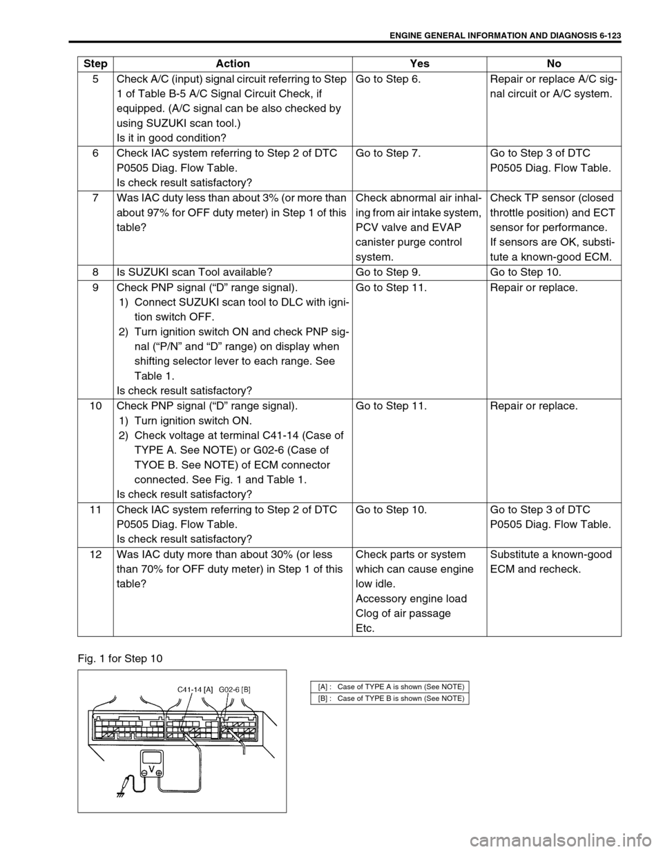
Fig. 1 for Step 105 Check A/C (input) signal circuit referring to Step
1 of Table B-5 A/C Signal Circuit Check, if
equipped. (A/C signal can be also checked by
using SUZUKI scan tool.)
Is it in good condition?Go to Step 6. Repair or replace A/C sig-
nal circuit or A/C system.
6 Check IAC system referring to Step 2 of DTC
P0505 Diag. Flow Table.
Is check result satisfactory?Go to Step 7. Go to Step 3 of DTC
P0505 Diag. Flow Table.
7 Was IAC duty less than about 3% (or more than
about 97% for OFF duty meter) in Step 1 of this
table?Check abnormal air inhal-
ing from air intake system,
PCV valve and EVAP
canister purge control
system.Check TP sensor (closed
throttle position) and ECT
sensor for performance.
If sensors are OK, substi-
tute a known-good ECM.
8 Is SUZUKI scan Tool available? Go to Step 9. Go to Step 10.
9 Check PNP signal (“D” range signal).
1) Connect SUZUKI scan tool to DLC with igni-
tion switch OFF.
2) Turn ignition switch ON and check PNP sig-
nal (“P/N” and “D” range) on display when
shifting selector lever to each range. See
Table 1.
Is check result satisfactory?Go to Step 11. Repair or replace.
10 Check PNP signal (“D” range signal).
1) Turn ignition switch ON.
2) Check voltage at terminal C41-14 (Case of
TYPE A. See NOTE) or G02-6 (Case of
TYOE B. See NOTE) of ECM connector
connected. See Fig. 1 and Table 1.
Is check result satisfactory?Go to Step 11. Repair or replace.
11 Check IAC system referring to Step 2 of DTC
P0505 Diag. Flow Table.
Is check result satisfactory?Go to Step 10. Go to Step 3 of DTC
P0505 Diag. Flow Table.
12 Was IAC duty more than about 30% (or less
than 70% for OFF duty meter) in Step 1 of this
table?Check parts or system
which can cause engine
low idle.
Accessory engine load
Clog of air passage
Etc.Substitute a known-good
ECM and recheck. Step Action Yes No
[A] : Case of TYPE A is shown (See NOTE)
[B] : Case of TYPE B is shown (See NOTE)
Page 495 of 698
![SUZUKI SWIFT 2000 1.G RG413 Service Workshop Manual 6-126 ENGINE GENERAL INFORMATION AND DIAGNOSIS
TABLE B-6 ELECTRIC LOAD SIGNAL CIRCUIT CHECK
INSPECTION
1. Blower fan motor 3. Rear defogger 5. To A/C switch
2. Blower fan switch 4. Position lamp
[A] : SUZUKI SWIFT 2000 1.G RG413 Service Workshop Manual 6-126 ENGINE GENERAL INFORMATION AND DIAGNOSIS
TABLE B-6 ELECTRIC LOAD SIGNAL CIRCUIT CHECK
INSPECTION
1. Blower fan motor 3. Rear defogger 5. To A/C switch
2. Blower fan switch 4. Position lamp
[A] :](/manual-img/20/7606/w960_7606-494.png)
6-126 ENGINE GENERAL INFORMATION AND DIAGNOSIS
TABLE B-6 ELECTRIC LOAD SIGNAL CIRCUIT CHECK
INSPECTION
1. Blower fan motor 3. Rear defogger 5. To A/C switch
2. Blower fan switch 4. Position lamp
[A] : Case of TYPE A is shown (See NOTE) [B] : Case of TYPE B is shown (See NOTE)
IG2
M
ECM
PNK/BLUG02-13
C42 (31P) C41 (24P) G02 (17P)1 2 3 4 5 6 7 8 9
10 11 12 13 14 15 16 17 18 19 20 21
22 23 24 25 26 28 27 29 30 315 6
1 2 3 4 5 6 7
11 12
9 10 11 13 12 14 15 16
16 171 2
7 8
13 14 3 4
9 10
15 17 188
19 20 21 22 23 24
RED/BLK [A]
IG11
+BB
43 25 1
C42-17 [A]
C41-17 [B] RED/YEL [B]
NOTE:
For TYPE A and TYPE B, refer to NOTE in “ECM VOLTAGE VALUES TABLE” for applicable model.
Step Action Yes No
1 Is SUZUKI scan tool available? Go to Step 2. Go to Step 3.
2 Check Electric Load Signal Circuit.
1) Connect SUZUKI scan tool to DLC with igni-
tion switch OFF.
2) Start engine and select “DATA LIST” mode
on scan tool.
3) Check electric load signal under following
each condition. See Fig. 1 and Table 1.
Is check result satisfactory?Electric load signal circuit
is in good condition.“RED/BLK” (Case of
TYPE A. See NOTE) or
C41-17 (Case of TYPE B.
See NOTE) and/or “PNK/
BLU” circuit open or short,
Electric load diodes mal-
function or Each electric
load circuit malfunction.
3 Check Electric Load Signal Circuit.
1) Turn ignition switch ON.
2) Check voltage at each terminals C42-17
(Case of TYPE A. See NOTE) or C41-17
(Case of TYPE B. See NOTE) and G02-13
of ECM connector connected, under above
each condition. See Fig. 2 and Table 1.
Is each voltage as specified?Electric load signal circuit
is in good condition.“RED/BLK” (Case of
TYPE A. See NOTE) or
C41-17 (Case of TYPE B.
See NOTE) and/or “PNK/
BLU” circuit open or short,
Electric load diodes mal-
function or Each electric
load circuit malfunction.
Page 657 of 698

6E1-36 ENGINE AND EMISSION CONTROL SYSTEM
OUTPUT SIGNALS OF THROTTLE VALVE OPENING
AND ENGINE COOLANT TEMP. (VEHICLE WITH A/T
ONLY)
THROTTLE VALVE OPENING SIGNAL INSPECTION
Check throttle valve opening (throttle position) signal referring to
step 1 of DTC P1700 (No.32 or 33) Flow Table in Section 7B. If
check result is not satisfactory, check each wire harness, circuit
connections and TP sensor.
ENGINE COOLANT TEMP. SIGNAL INSPECTION
Check engine coolant temp. signal referring to step 1 of DTC
P1705 (NO.51) Flow Table in Section 7B.
If check result is not satisfactory, check each wire harness, circuit
connection and ECT sensor.
EMISSION CONTROL SYSTEM
EGR SYSTEM
SYSTEM INSPECTION (USING SUZUKI SCAN TOOL)
1) Connect SUZUKI scan tool to DLC with ignition switch OFF.
2) Turn ignition switch ON and then select “DATA LIST” mode
on scan tool.
3) Make sure that vehicle condition is as following.
Vehicle speed = 0 km/h (0 KPH)
Engine speed ≤ 3000 rpm
4) Clear DTC by using “CLEAR INFO” mode.
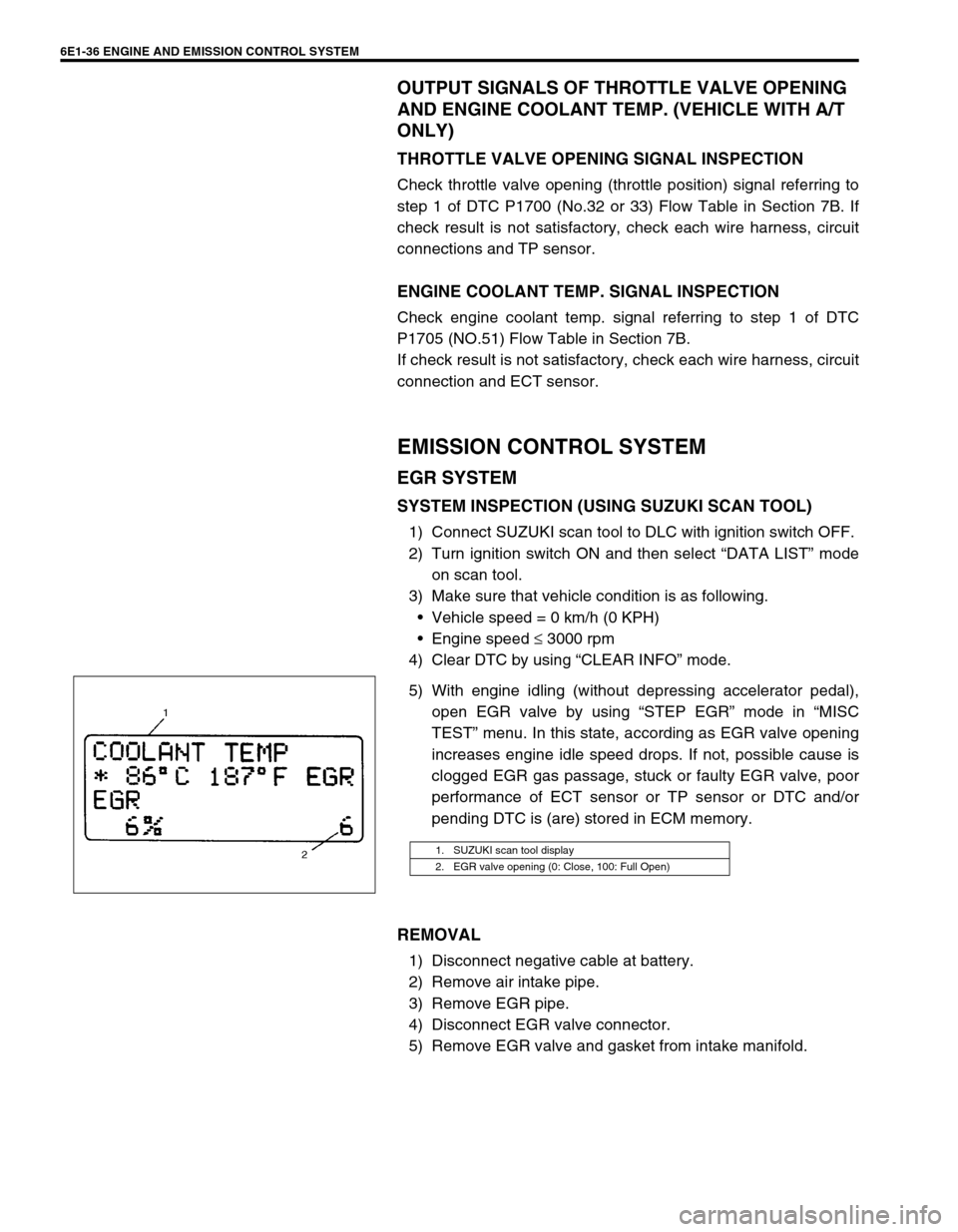
5) With engine idling (without depressing accelerator pedal),
open EGR valve by using “STEP EGR” mode in “MISC
TEST” menu. In this state, according as EGR valve opening
increases engine idle speed drops. If not, possible cause is
clogged EGR gas passage, stuck or faulty EGR valve, poor
performance of ECT sensor or TP sensor or DTC and/or
pending DTC is (are) stored in ECM memory.
REMOVAL
1) Disconnect negative cable at battery.
2) Remove air intake pipe.
3) Remove EGR pipe.
4) Disconnect EGR valve connector.
5) Remove EGR valve and gasket from intake manifold.
1. SUZUKI scan tool display
2. EGR valve opening (0: Close, 100: Full Open)
Page 664 of 698

6F1-2 IGNITION SYSTEM (ELECTRONIC IGNITION SYSTEM)
GENERAL DESCRIPTION
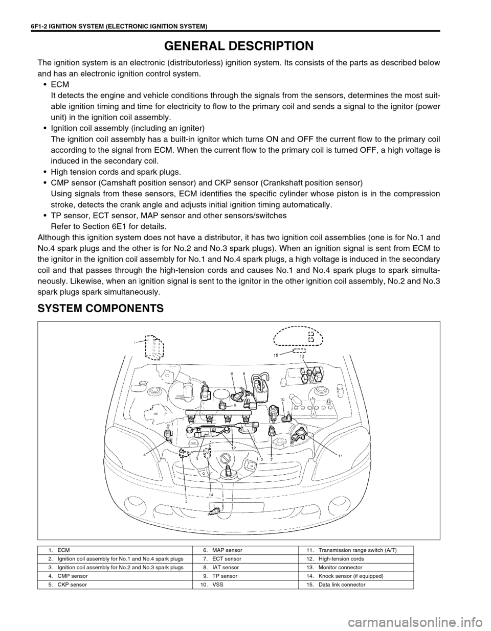
The ignition system is an electronic (distributorless) ignition system. Its consists of the parts as described below
and has an electronic ignition control system.
ECM
It detects the engine and vehicle conditions through the signals from the sensors, determines the most suit-
able ignition timing and time for electricity to flow to the primary coil and sends a signal to the ignitor (power
unit) in the ignition coil assembly.
Ignition coil assembly (including an igniter)
The ignition coil assembly has a built-in ignitor which turns ON and OFF the current flow to the primary coil
according to the signal from ECM. When the current flow to the primary coil is turned OFF, a high voltage is
induced in the secondary coil.
High tension cords and spark plugs.
CMP sensor (Camshaft position sensor) and CKP sensor (Crankshaft position sensor)
Using signals from these sensors, ECM identifies the specific cylinder whose piston is in the compression
stroke, detects the crank angle and adjusts initial ignition timing automatically.
TP sensor, ECT sensor, MAP sensor and other sensors/switches
Refer to Section 6E1 for details.
Although this ignition system does not have a distributor, it has two ignition coil assemblies (one is for No.1 and
No.4 spark plugs and the other is for No.2 and No.3 spark plugs). When an ignition signal is sent from ECM to
the ignitor in the ignition coil assembly for No.1 and No.4 spark plugs, a high voltage is induced in the secondary
coil and that passes through the high-tension cords and causes No.1 and No.4 spark plugs to spark simulta-
neously. Likewise, when an ignition signal is sent to the ignitor in the other ignition coil assembly, No.2 and No.3
spark plugs spark simultaneously.
SYSTEM COMPONENTS
1. ECM 6. MAP sensor 11. Transmission range switch (A/T)
2. Ignition coil assembly for No.1 and No.4 spark plugs 7. ECT sensor 12. High-tension cords
3. Ignition coil assembly for No.2 and No.3 spark plugs 8. IAT sensor 13. Monitor connector
4. CMP sensor 9. TP sensor 14. Knock sensor (if equipped)
5. CKP sensor 10. VSS 15. Data link connector