Page 153 of 698
3B1-12 ELECTRICAL POWER STEERING (P/S) SYSTEM
DTC (displayed
on SUZUKI scan
tool)“EPS” light flashing pattern
DTC (indicated
by “EPS” light
flashing pattern)Model DIAGNOSTIC ITEM DIAGNOSIS
NO DTC 12 NormalThis code appears
when none of the other
codes are identified.
C1111 11
Torque sensor
Diagnose trouble
according to “DIAG-
NOSTIC FLOW
TABLE” corresponding
to each code No. C1113 13
C1114 14
C1115 15
C1116 16
C1121 21
VSS signal C1123 23
C1124 24
C1122 22Engine speed sig-
nal
C1141 41
Motor C1142 42
C1143 43
C1144 44
C1145 45
C1151 51 Clutch
C1152 52
P/S control module C1154 54
C1155 55
C1153 53P/S control module
power supply
Page 157 of 698

3B1-16 ELECTRICAL POWER STEERING (P/S) SYSTEM
DTC C1111 (DTC No.11) TORQUE SENSOR MAIN CIRCUIT FAILURE
DTC C1113 (DTC No.13) TORQUE SENSOR MAIN AND SUB CIRCUIT FAILURE
DTC C1115 (DTC No.15) TORQUE SENSOR SUB CIRCUIT FAILURE
1. To main fuse 4.“IG METER” fuse (15A) in fuse box 7. Connector “G24”
2. Ignition switch 5. P/S control module 8. Connector “G24-1”
3.“P/S” fuse (30A) in fuse box 6. Torque sensor
G24-2 G24-1
G24-8G24-1-4 G24-1-3
G24-1-5G24-1-2G24-1-1
1
23
45
6
BLK/WHT BLK/RED
BLK WHTYEL BLK BLU RED
G24-1
G24-8G24-2
7
G24-1-5
G24-1-4 G24-1-3 G24-1-2 G24-1-18
Step Action Yes No
11)Was “SYSTEM CHECK FLOW TABLE” per-
formed?Go to STEP 2. Go to “SYSTEM CHECK
FLOW TABLE”.
2 1) Is DTC C1114 (DTC No.14) or C1116 (DTC
No.16) indicated, too?Go to flow table corre-
sponding to each DTC
No.Go to STEP 3.
3 1) Check proper connection for 5-terminals
connector (“G24-1”) to P/S control module.
2) If OK, check torque sensor and its circuit.
Refer to “TORQUE SENSOR”.
Is torque sensor in good condition?Substitute a known-good
P/S control module and
recheck.Replace steering column
assembly and recheck.
Page 158 of 698

ELECTRICAL POWER STEERING (P/S) SYSTEM 3B1-17
DTC C1114 (DTC No.14) TORQUE SENSOR 5V POWER SUPPLY CIRCUIT FAIL-
URE
Fig. for Step 2
1. To main fuse 4.“IG METER” fuse (15A) in fuse box 7. Connector “G24”
2. Ignition switch 5. P/S control module 8. Connector “G24-1”
3.“P/S” fuse (30A) in fuse box 6. Torque sensor
G24-1
G24-8G24-2
7
G24-1-5
G24-1-4 G24-1-3 G24-1-2 G24-1-18
G24-2 G24-1
G24-8G24-1-4G24-1-3
G24-1-5G24-1-2G24-1-1
1
23
45
6
BLK/WHT BLK/RED
BLK WHTYEL BLK BLU RED
Step Action Yes No
1Was “SYSTEM CHECK FLOW TABLE” per-
formed?Go to STEP 2. Go to “SYSTEM CHECK
FLOW TABLE”.
2 1) Remove steering column hole cover.
2) Check proper connection for 5-terminals
connector (“G24-1”) to P/S control module.
3) If OK, turn ignition switch ON.
4) Check voltage between “G24-1-2” (“BLU”
wire) terminal of 5-terminals connector
(“G24-1”) and body ground with connector
(“G24-1”) connected to P/S control module.
Is it about 5 V?Go to STEP 3. Repair high resistance,
open or short to power cir-
cuit or ground in 5V power
supply (“BLU” wire) cir-
cuit.
3 1) Check torque sensor and its circuit. Refer to
“TORQUE SENSOR”.
Is torque sensor in good condition?Substitute a known-good
P/S control module and
recheck.Replace steering column
assembly and recheck.
Page 159 of 698

3B1-18 ELECTRICAL POWER STEERING (P/S) SYSTEM
DTC C1116 (DTC No.16) TORQUE SENSOR 8V POWER SUPPLY CIRCUIT FAIL-
URE
Fig. for Step 2
1. To main fuse 4.“IG METER” fuse (15A) in fuse box 7. Connector “G24”
2. Ignition switch 5. P/S control module 8. Connector “G24-1”
3.“P/S” fuse (30A) in fuse box 6. Torque sensor
G24-1
G24-8G24-2
7
G24-1-5
G24-1-4 G24-1-3 G24-1-2 G24-1-18
G24-2 G24-1
G24-8G24-1-4 G24-1-3
G24-1-5 G24-1-2 G24-1-1
1
23
45
6
BLK/WHTBLK/RED
BLK WHTYEL BLK BLU RED
Step Action Yes No
1Was “SYSTEM CHECK FLOW TABLE” per-
formed?Go to STEP 2. Go to “SYSTEM CHECK
FLOW TABLE”.
2 1) Remove steering column hole cover.
2) Check proper connection for 5-terminals
connector (“G24-1”) to P/S control module.
3) If OK, turn ignition switch ON.
4) Measure voltage between “G24-1-1” (“RED”
wire) terminal of 5-terminals connector
(“G24-1”) and body ground with connector
(“G24-1”) connected to P/S control module.
Is it about 8 V?Go to STEP 3. Repair high resistance,
open or short to power cir-
cuit or ground in 8V power
supply (“RED” wire) cir-
cuit.
3 1) Check torque sensor and its circuit. Refer to
“TORQUE SENSOR”.
Is torque sensor in good condition?Substitute a known-good
P/S control module and
recheck.Replace steering column
assembly and recheck.
Page 166 of 698

ELECTRICAL POWER STEERING (P/S) SYSTEM 3B1-25
TROUBLE DIAGNOSIS (FOR TROUBLE NOT INDICATED BY ON BOARD DIAG-
NOSTIC SYSTEM)
This section describes trouble diagnosis of P/S system parts whose trouble is not indicated by the on-board
diagnostic system (self-diagnostic function).
When DTC No.12 is indicated by the on-board diagnostic system (self-diagnosis function) and assuredly those
steering basic parts as described in “DIAGNOSIS TABLE” in Section 3 are all in good condition, check the fol-
lowing power steering system parts which may be a possible cause for each symptom of the steering.
Condition Possible Cause Correction
Steering wheel feels
heavy (Perform
STEERING FORCE
INSPECTION before
diagnosis.)Steering wheel installed improperly (twisted) Install steering wheel correctly.
Poor performance of torque sensor Check torque sensor. Refer to
“TORQUE SENSOR”.
Poor performance of motor and clutch Check motor and clutch. Refer to
“MOTOR AND CLUTCH”.
Faulty steering column Replace.
Poor performance of VSS Check VSS. Refer to Section 6E.
Vehicle pulls to one
side during straight
drivingPoor performance of torque sensor Check torque sensor. Refer to
“TORQUE SENSOR”.
Poor recovery from
turnsPoor performance of torque sensor Check torque sensor. Refer to
“TORQUE SENSOR”.
Faulty steering column Replace.
Page 168 of 698

ELECTRICAL POWER STEERING (P/S) SYSTEM 3B1-27
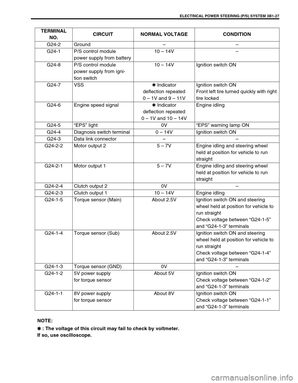
TERMINAL
NO.CIRCUIT NORMAL VOLTAGE CONDITION
G24-2 Ground––
G24-1 P/S control module
power supply from battery10 – 14V–
G24-8 P/S control module
power supply from igni-
tion switch10 – 14V Ignition switch ON
G24-7 VSS✱ Indicator
deflection repeated
0 – 1V and 9 – 11VIgnition switch ON
Front left tire turned quickly with right
tire locked
G24-6 Engine speed signal✱ Indicator
deflection repeated
0 – 1V and 10 – 14VEngine idling
G24-5“EPS” light 0V“EPS” warning lamp ON
G24-4 Diagnosis switch terminal 0 – 14V Ignition switch ON
G24-3 Data link connector––
G24-2-2 Motor output 2 5 – 7V Engine idling and steering wheel
held at position for vehicle to run
straight
G24-2-1 Motor output 1 5 – 7V Engine idling and steering wheel
held at position for vehicle to run
straight
G24-2-4 Clutch output 2 0V–
G24-2-3 Clutch output 1 10 – 14V Engine idling
G24-1-5 Torque sensor (Main) About 2.5V Ignition switch ON and steering
wheel held at position for vehicle to
run straight
Check voltage between “G24-1-5”
and “G24-1-3” terminals
G24-1-4 Torque sensor (Sub) About 2.5V Ignition switch ON and steering
wheel held at position for vehicle to
run straight
Check voltage between “G24-1-4”
and “G24-1-3” terminals
G24-1-3 Torque sensor (GND) 0V–
G24-1-2 5V power supply
for torque sensorAbout 5V Ignition switch ON
Check voltage between “G24-1-2”
and “G24-1-3” terminals
G24-1-1 8V power supply
for torque sensorAbout 8V Ignition switch ON
Check voltage between “G24-1-1”
and “G24-1-3” terminals
NOTE:
✱
✱✱ ✱ : The voltage of this circuit may fail to check by voltmeter.
If so, use oscilloscope.
Page 170 of 698

ELECTRICAL POWER STEERING (P/S) SYSTEM 3B1-29
ON-VEHICLE SERVICE
P/S CONTROL MODULE
REMOVAL
1) Disconnect negative cable at battery.
2) Remove steering column hole cover.
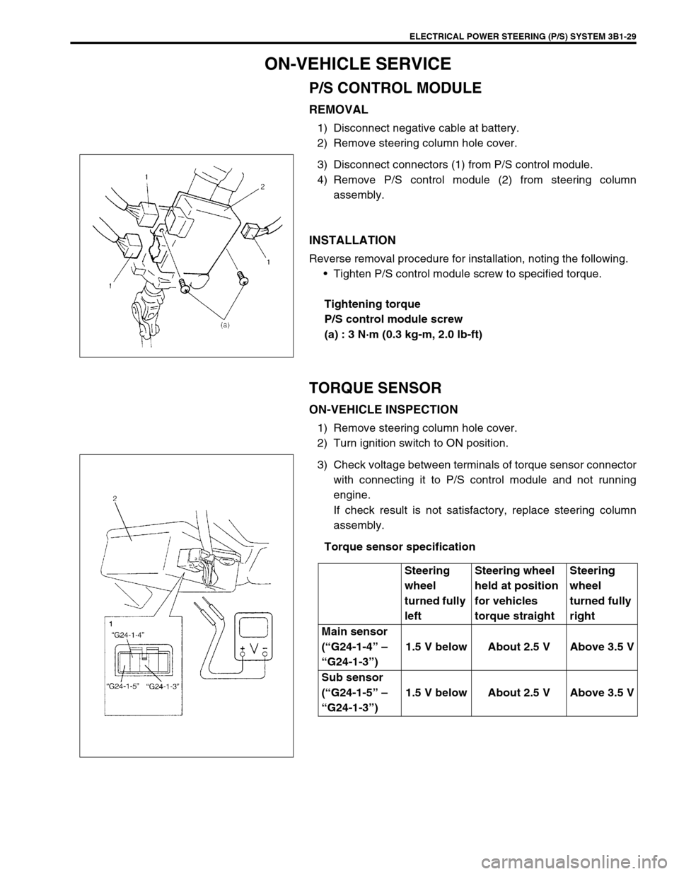
3) Disconnect connectors (1) from P/S control module.
4) Remove P/S control module (2) from steering column
assembly.
INSTALLATION
Reverse removal procedure for installation, noting the following.
Tighten P/S control module screw to specified torque.
Tightening torque
P/S control module screw
(a) : 3 N·m (0.3 kg-m, 2.0 lb-ft)
TORQUE SENSOR
ON-VEHICLE INSPECTION
1) Remove steering column hole cover.
2) Turn ignition switch to ON position.
3) Check voltage between terminals of torque sensor connector
with connecting it to P/S control module and not running
engine.
If check result is not satisfactory, replace steering column
assembly.
Torque sensor specification
Steering
wheel
turned fully
leftSteering wheel
held at position
for vehicles
torque straightSteering
wheel
turned fully
right
Main sensor
(“G24-1-4” –
“G24-1-3”)1.5 V below About 2.5 V Above 3.5 V
Sub sensor
(“G24-1-5” –
“G24-1-3”)1.5 V below About 2.5 V Above 3.5 V
Page 205 of 698
3D-12 FRONT SUSPENSION
7) Pull out wheel hub (1) with special tools.
Special tool
(A) : 09943-17912
(B) : 09942-15510
8) Disconnect tie rod end (1) from steering knuckle (2) with
special tool.
Special tool
(A) : 09913-65210
9) Remove wheel speed sensor (1) from knuckle (if equipped
with ABS).
10) Loosen strut bracket nuts (1).
11) Remove ball joint bolt (3).
12) Remove strut bracket bolts from strut bracket and then steer-
ing knuckle (2). CAUTION:
When wheel hub is removed, replace wheel bearing as a
set.
F: Forward
R: Rearward