2000 SUZUKI SWIFT service indicator
[x] Cancel search: service indicatorPage 416 of 698

ENGINE GENERAL INFORMATION AND DIAGNOSIS 6-47
TABLE A-2 MALFUNCTION INDICATOR LAMP CIRCUIT CHECK - LAMP
REMAINS “ON” AFTER ENGINE STARTS
WIRING DIAGRAM / CIRCUIT DESCRIPTION
Refer to table A-1.
INSPECTION
3 MIL Circuit Check
1) Turn ignition switch OFF and disconnect
connectors from ECM.
2) Check for proper connection to ECM at ter-
minal G02-1 (Case of TYPE A. See NOTE)
or G02-9 (Case of TYPE B. See NOTE).
3) If OK, then using service wire, ground termi-
nal G02-1 (Case of TYPE A. See NOTE) or
G02-9 (Case of TYPE B. See NOTE) in con-
nector disconnected.
Does MIL turn on at ignition switch ON?Substitute a known-good
ECM and recheck.Bulb burned out or “PPL/
YEL” (Case of TYPE A.
See NOTE) or “PPL/
WHT” (Case of TYPE B.
See NOTE) wire circuit
open.
Test switch terminal cir-
cuit grounded (vehicle
without immobilizer indi-
cator lamp) Step Action Yes No
NOTE:
For TYPE A and TYPE B, refer to NOTE in “ECM VOLTAGE VALUES TABLE” for applicable model.
Step Action Yes No
1 Diagnostic Trouble Code (DTC) Check
1) Check DTC referring to DTC CHECK
section.
Is there any DTC(s)?Go to Step 2 of ENGINE DIAG.
FLOW TABLE.Go to Step 2.
2DTC Check
1) Start engine and recheck DTC while
engine running.
Is there any DTC(s)?Go to Step 3.
3 MIL Circuit Check
1) Turn OFF ignition switch.
2) Disconnect connectors from ECM.
Does MIL turn ON at ignition switch ON?“PPL/YEL” (Case of TYPE A.
See NOTE) or “PPL/WHT”
(Case of TYPE B. See NOTE)
wire circuit shorted to ground.Substitute a known-good
ECM and recheck.
Page 417 of 698

6-48 ENGINE GENERAL INFORMATION AND DIAGNOSIS
TABLE A-3 MIL CHECK - MIL FLASHES AT IGNITION SWITCH ON (VEHICLE
WITHOUT IMMOBILIZER INDICATOR LAMP)
WIRING DIAGRAM / CIRCUIT DESCRIPTION
Refer to TABLE A-1.
INSPECTION
TABLE A-4 MIL CHECK - MIL DOES NOT FLASH OR JUST REMAINS ON EVEN
WITH GROUNDING DIAGNOSIS SWITCH TERMINAL (VEHICLE WITHOUT
IMMOBILIZER INDICATOR LAMP)
WIRING DIAGRAM / CIRCUIT DESCRIPTION
Refer to TABLE A-1.
INSPECTION
NOTE:
For TYPE A and TYPE B, refer to NOTE in “ECM VOLTAGE VALUES TABLE” for applicable model.
Step Action Yes No
1 MIL Flashing Pattern Check
1) Turn ignition switch ON.
Does lamp flashing pattern indicate diag-
nostic trouble code?Go to Step 2. Substitute a known-good ECM
and recheck.
2 Diag. Switch Circuit Check
Is diag. switch terminal connected to
ground via service wire?System is in good condi-
tion.“PPL/WHT” circuit for monitor
connector shorted to ground. If
circuit is OK substitute a known-
good ECM and recheck.
NOTE:
For TYPE A and TYPE B, refer to NOTE in “ECM VOLTAGE VALUES TABLE” for applicable model.
Step Action Yes No
1 MIL Circuit Check
1) Turn ignition switch OFF and disconnect connec-
tors from ECM.
Does MIL turn ON at ignition switch ON?“PPL/YEL” (Case of TYPE A.
See NOTE) or “PPL/WHT”
(Case of TYPE B. See NOTE)
circuit shorted to ground.Go to Step 2.
2 ECM/PCM Connection Check
1) Turn ignition switch OFF.
Is connector (C42-27 (Case of TYPE A. See NOTE)
or C41-14 (Case of TYPE B. See NOTE) connection)
connected to ECM/PCM properly?Go to Step 3. Poor connector connec-
tion.
3 Diag. Switch Terminal Circuit Check
1) Connect connectors to ECM.
2) Using service wire, ground C42-27 (Case of
TYPE A. See NOTE) or C41-14 (Case of TYPE
B. See NOTE) connection) terminal with connec-
tors connected to ECM.
3) Turn ignition switch ON.
Does MIL flash?“PPL/WHT” or “BLK” circuit in
monitor connector is open.Substitute a known-good
ECM and recheck.
Page 622 of 698

ENGINE AND EMISSION CONTROL SYSTEM 6E1-1
6F1
6F2
6G
6H
6E1
7A
7A1
7B1
7C1
7D
7E
7F
8A
8B
8C
8D
8E
9
10
10A
10B
SECTION 6E1
ENGINE AND EMISSION CONTROL SYSTEM
CONTENTS
GENERAL DESCRIPTION ............................ 6E1-2
AIR INTAKE SYSTEM ............................... 6E1-5
FUEL DELIVERY SYSTEM ....................... 6E1-6
FUEL PUMP ........................................... 6E1-6
ELECTRONIC CONTROL SYSTEM .......... 6E1-7
ENGINE & EMISSION CONTROL
INPUT/OUTPUT TABLE ........................ 6E1-8
ECM INPUT/OUTPUT CIRCUIT
DIAGRAM............................................... 6E1-9
ECM TERMINAL ARRANGEMENT
TABLE .................................................. 6E1-13
ON-VEHICLE SERVICE .............................. 6E1-15
ACCELERATOR CABLE
ADJUSTMENT ..................................... 6E1-15
IDLE SPEED/IDLE AIR CONTROL
(IAC) DUTY INSPECTION ................... 6E1-15
IDLE MIXTURE INSPECTION /
ADJUSTMENT (VEHICLE WITHOUT
HEATED OXYGEN SENSOR) ............. 6E1-17
AIR INTAKE SYSTEM ............................. 6E1-18
THROTTLE BODY ............................... 6E1-18IDLE AIR CONTROL VALVE (IAC
VALVE) ................................................ 6E1-20
FUEL DELIVERY SYSTEM ..................... 6E1-21
FUEL PRESSURE INSPECTION ........ 6E1-21
FUEL PUMP WITH PRESSURE
REGULATOR ....................................... 6E1-22
FUEL INJECTOR ................................. 6E1-23
ELECTRONIC CONTROL SYSTEM ....... 6E1-27
ENGINE CONTROL MODULE
(ECM) ................................................... 6E1-27
MANIFOLD ABSOLUTE PRESSURE
SENSOR (MAP SENSOR)................... 6E1-27
THROTTLE POSITION SENSOR (TP
SENSOR) ............................................. 6E1-28
INTAKE AIR TEMPERATURE
SENSOR (IAT SENSOR) ..................... 6E1-29
ENGINE COOLANT TEMPERATURE
SENSOR (ECT SENSOR) ................... 6E1-30
HEATED OXYGEN SENSOR (HO2S-1
AND HO2S-2) ...................................... 6E1-31
CAMSHAFT POSITION SENSOR ....... 6E1-32 WARNING:
For vehicles equipped with Supplemental Restraint (Air Bag) System :
Service on and around the air bag system components or wiring must be performed only by an
authorized SUZUKI dealer. Refer to “Air Bag System Components and Wiring Location View” under
“General Description” in air bag system section in order to confirm whether you are performing ser-
vice on or near the air bag system components or wiring. Please observe all WARNINGS and “Ser-
vice Precautions” under “On-Vehicle Service” in air bag system section before performing service
on or around the air bag system components or wiring. Failure to follow WARNINGS could result in
unintentional activation of the system or could render the system inoperative. Either of these two
conditions may result in severe injury.
Technical service work must be started at least 90 seconds after the ignition switch is turned to the
“LOCK” position and the negative cable is disconnected from the battery. Otherwise, the system
may be activated by reserve energy in the Sensing and Diagnostic Module (SDM).
NOTE:
Whether the following system (parts) are used in the particular vehicle or not depends on vehicle
specifications. Be sure to bear this in mind when performing service work.
EGR valve
Heated oxygen sensor(s) or CO adjusting resistor
Three way catalytic converter
Immobilizer indicator lamp
Knock sensor
Page 637 of 698

6E1-16 ENGINE AND EMISSION CONTROL SYSTEM
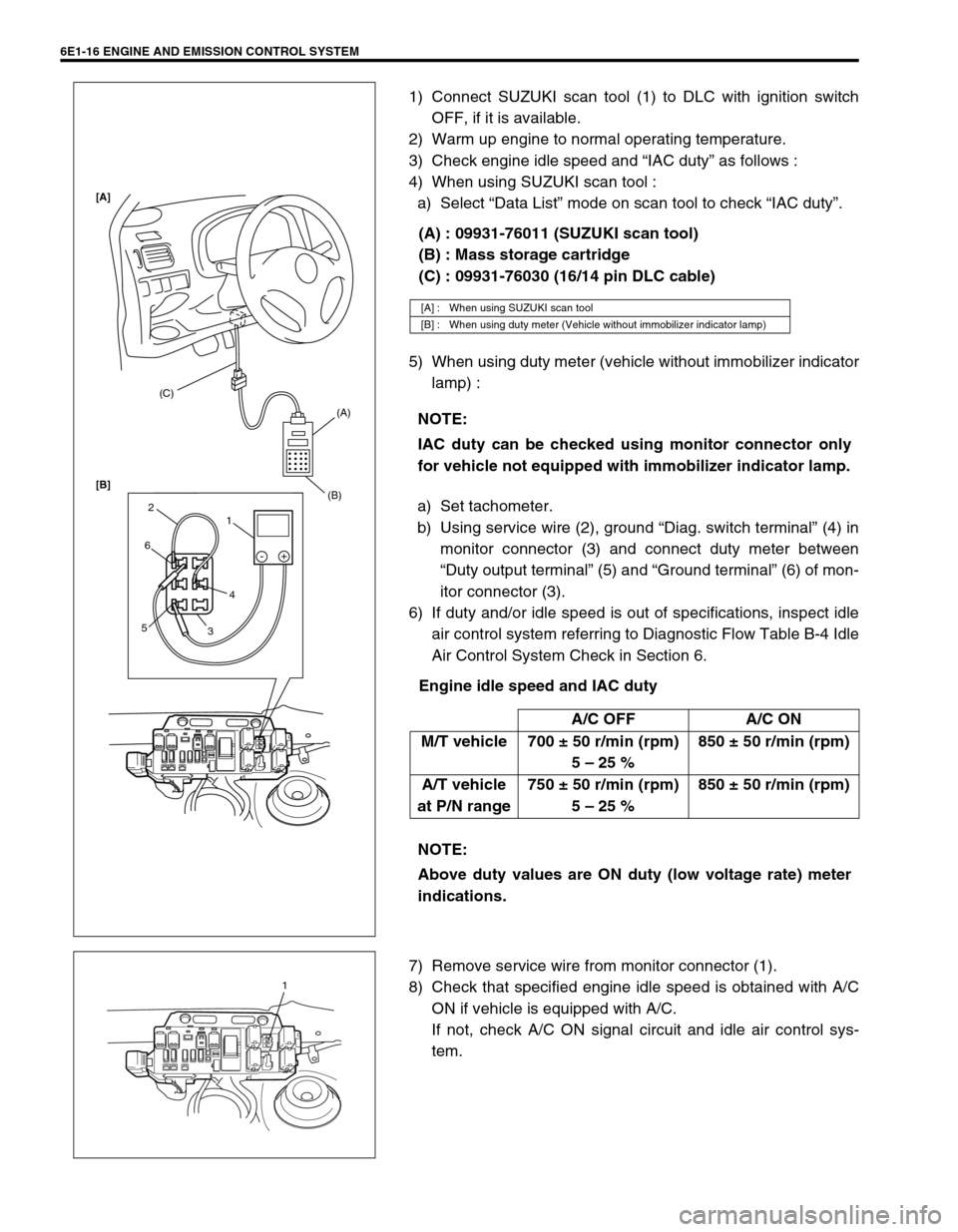
1) Connect SUZUKI scan tool (1) to DLC with ignition switch
OFF, if it is available.
2) Warm up engine to normal operating temperature.
3) Check engine idle speed and “IAC duty” as follows :
4) When using SUZUKI scan tool :
a) Select “Data List” mode on scan tool to check “IAC duty”.
(A) : 09931-76011 (SUZUKI scan tool)
(B) : Mass storage cartridge
(C) : 09931-76030 (16/14 pin DLC cable)
5) When using duty meter (vehicle without immobilizer indicator
lamp) :
a) Set tachometer.
b) Using service wire (2), ground “Diag. switch terminal” (4) in
monitor connector (3) and connect duty meter between
“Duty output terminal” (5) and “Ground terminal” (6) of mon-
itor connector (3).
6) If duty and/or idle speed is out of specifications, inspect idle
air control system referring to Diagnostic Flow Table B-4 Idle
Air Control System Check in Section 6.
Engine idle speed and IAC duty
7) Remove service wire from monitor connector (1).
8) Check that specified engine idle speed is obtained with A/C
ON if vehicle is equipped with A/C.
If not, check A/C ON signal circuit and idle air control sys-
tem.
[A] : When using SUZUKI scan tool
[B] : When using duty meter (Vehicle without immobilizer indicator lamp)
NOTE:
IAC duty can be checked using monitor connector only
for vehicle not equipped with immobilizer indicator lamp.
A/C OFF A/C ON
M/T vehicle 700 ± 50 r/min (rpm)
5 – 25 %850 ± 50 r/min (rpm)
A/T vehicle
at P/N range750 ± 50 r/min (rpm)
5 – 25 %850 ± 50 r/min (rpm)
NOTE:
Above duty values are ON duty (low voltage rate) meter
indications.
(C)
(A)
(B)
1 2
6
54
3-+
[A]
[B]
1
Page 681 of 698

CHARGING SYSTEM 6H-1
6F1
6F2
6G
6K
7A
6H
7B1
7C1
7D
7E
7F
8A
8B
8C
8D
8E
9
10
10A
10B
SECTION 6H
CHARGING SYSTEM
CONTENTS
GENERAL DESCRIPTION .............................. 6H-2
BATTERY ..................................................... 6H-2
CARRIER AND HOLD-DOWN ................. 6H-2
ELECTROLYTE FREEZING .................... 6H-2
SULFATION ............................................. 6H-2
BUILT-IN INDICATOR (IF EQUIPPED) ... 6H-2
CARE OF BATTERY ................................ 6H-3
GENERATOR .............................................. 6H-4
DIAGNOSIS ..................................................... 6H-5
BATTERY ..................................................... 6H-5
VISUAL INSPECTION.............................. 6H-5
HYDROMETER TEST.............................. 6H-5
GENERATOR .............................................. 6H-6
CHARGING INDICATOR LAMP
OPERATION ............................................ 6H-6
UNDERCHARGED BATTERY ................. 6H-7
OVERCHARGED BATTERY.................... 6H-8ON-VEHICLE SERVICE .................................. 6H-9
BATTERY .................................................... 6H-9
JUMP STARTING IN CASE OF
EMERGENCY .......................................... 6H-9
DISMOUNTING...................................... 6H-10
HANDLING............................................. 6H-10
REMOUNTING....................................... 6H-10
GENERATOR ............................................ 6H-10
GENERATOR BELT .............................. 6H-10
DISMOUNTING AND REMOUNTING ... 6H-11
DISASSEMBLY AND REASSEMBLY .... 6H-11
INSPECTION ......................................... 6H-12
SPECIFICATION ........................................... 6H-14
BATTERY .................................................. 6H-14
GENERATOR ............................................ 6H-14
TIGHTENING TORQUE SPECIFICATION.... 6H-14
WARNING:
For vehicles equipped with Supplemental Restraint (Air Bag) System:
Service on and around the air bag system components or wiring must be performed only by an
authorized SUZUKI dealer. Refer to “Air Bag System Components and Wiring Location View” under
“General Description” in air bag system section in order to confirm whether you are performing ser-
vice on or near the air bag system components or wiring. Please observe all WARNINGS and “Ser-
vice Precautions” under “On-Vehicle Service” in air bag system section before performing service
on or around the air bag system components or wiring. Failure to follow WARNINGS could result in
unintentional activation of the system or could render the system inoperative. Either of these two
conditions may result in severe injury.
Technical service work must be started at least 90 seconds after the ignition switch is turned to the
“LOCK” position and the negative cable is disconnected from the battery. Otherwise, the system
may be activated by reserve energy in the Sensing and Diagnostic Module (SDM).
Page 684 of 698

6H-4 CHARGING SYSTEM
GENERATOR
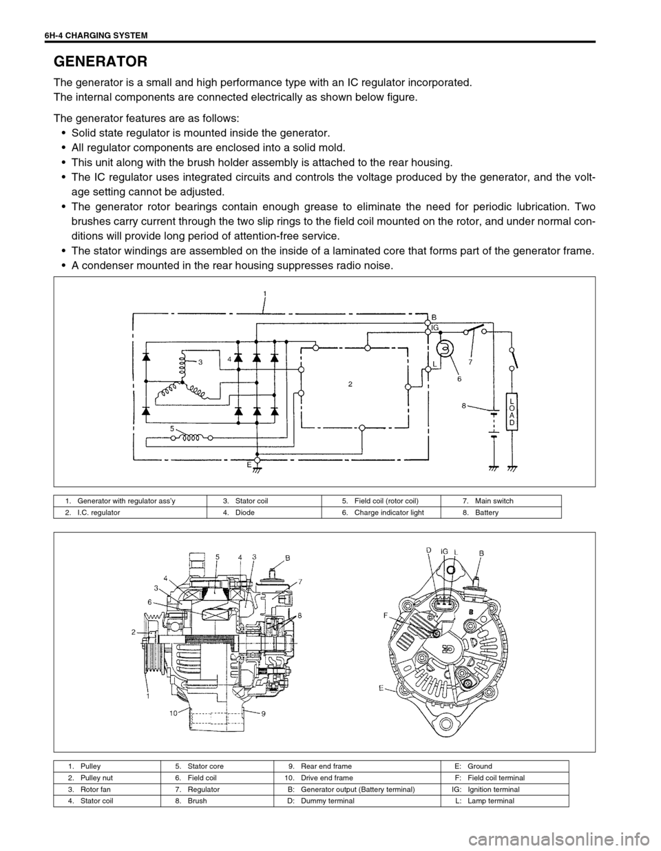
The generator is a small and high performance type with an IC regulator incorporated.
The internal components are connected electrically as shown below figure.
The generator features are as follows:
Solid state regulator is mounted inside the generator.
All regulator components are enclosed into a solid mold.
This unit along with the brush holder assembly is attached to the rear housing.
The IC regulator uses integrated circuits and controls the voltage produced by the generator, and the volt-
age setting cannot be adjusted.
The generator rotor bearings contain enough grease to eliminate the need for periodic lubrication. Two
brushes carry current through the two slip rings to the field coil mounted on the rotor, and under normal con-
ditions will provide long period of attention-free service.
The stator windings are assembled on the inside of a laminated core that forms part of the generator frame.
A condenser mounted in the rear housing suppresses radio noise.
1. Generator with regulator ass’y 3. Stator coil 5. Field coil (rotor coil) 7. Main switch
2. I.C. regulator 4. Diode 6. Charge indicator light 8. Battery
1. Pulley 5. Stator core 9. Rear end frame E: Ground
2. Pulley nut 6. Field coil 10. Drive end frame F: Field coil terminal
3. Rotor fan 7. Regulator B: Generator output (Battery terminal) IG: Ignition terminal
4. Stator coil 8. Brush D: Dummy terminal L: Lamp terminal