2000 SUZUKI SWIFT air condition
[x] Cancel search: air conditionPage 663 of 698

IGNITION SYSTEM (ELECTRONIC IGNITION SYSTEM) 6F1-1
6G
6F2
6G
6H
6K
6F1
7A
7A1
7A1
7D
7E
7F
8A
8B
8C
8D
8E
9
10
10A
10B
SECTION 6F1
IGNITION SYSTEM
(ELECTRONIC IGNITION SYSTEM)
CONTENTS
GENERAL DESCRIPTION ............................. 6F1-2
DIAGNOSIS .................................................... 6F1-3
ON-VEHICLE SERVICE ................................. 6F1-5
IGNITION SPARK TEST ............................. 6F1-5
HIGH-TENSION CORDS ............................ 6F1-5
SPARK PLUGS ........................................... 6F1-6IGNITION COIL ASSEMBLY
(INCLUDING IGNITOR) .............................. 6F1-7
CRANKSHAFT POSITION SENSOR
(CKP SENSOR) .......................................... 6F1-7
IGNITION TIMING ...................................... 6F1-8
SPECIAL TOOL ............................................. 6F1-9
WARNING:
For vehicles equipped with Supplemental Restraint (Air Bag) System:
Service on and around the air bag system components or wiring must be performed only by an
authorized SUZUKI dealer. Refer to “Air Bag System Components and Wiring Location View” under
“General Description” in air bag system section in order to confirm whether you are performing ser-
vice on or near the air bag system components or wiring. Please observe all WARNINGS and “Ser-
vice Precautions” under “On-Vehicle Service” in air bag system section before performing service
on or around the air bag system components or wiring. Failure to follow WARNINGS could result in
unintentional activation of the system or could render the system inoperative. Either of these two
conditions may result in severe injury.
Technical service work must be started at least 90 seconds after the ignition switch is turned to the
“LOCK” position and the negative cable is disconnected from the battery. Otherwise, the system
may be activated by reserve energy in the Sensing and Diagnostic Module (SDM).
Page 666 of 698

6F1-4 IGNITION SYSTEM (ELECTRONIC IGNITION SYSTEM)
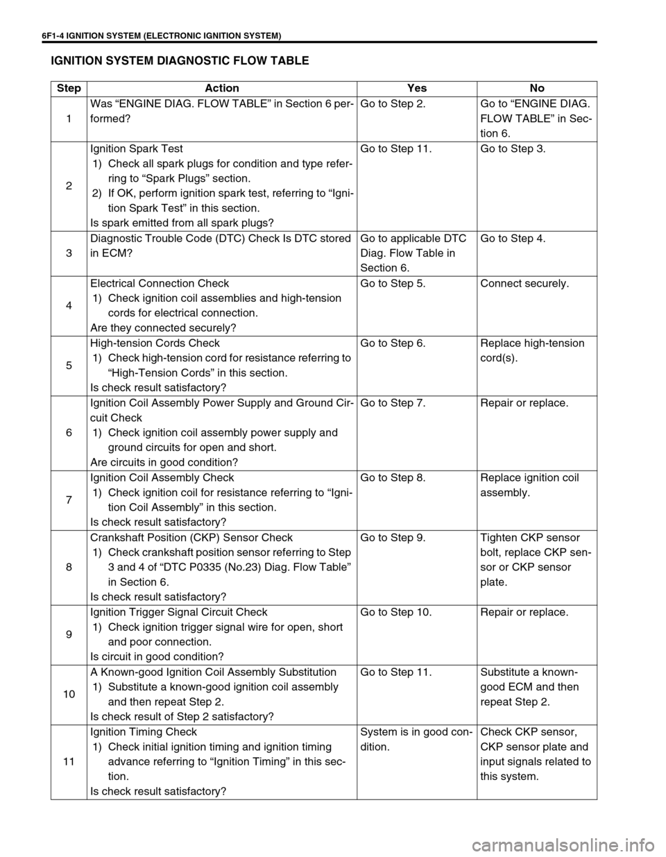
IGNITION SYSTEM DIAGNOSTIC FLOW TABLE
Step Action Yes No
1Was “ENGINE DIAG. FLOW TABLE” in Section 6 per-
formed?Go to Step 2. Go to “ENGINE DIAG.
FLOW TABLE” in Sec-
tion 6.
2Ignition Spark Test
1) Check all spark plugs for condition and type refer-
ring to “Spark Plugs” section.
2) If OK, perform ignition spark test, referring to “Igni-
tion Spark Test” in this section.
Is spark emitted from all spark plugs?Go to Step 11. Go to Step 3.
3Diagnostic Trouble Code (DTC) Check Is DTC stored
in ECM?Go to applicable DTC
Diag. Flow Table in
Section 6.Go to Step 4.
4Electrical Connection Check
1) Check ignition coil assemblies and high-tension
cords for electrical connection.
Are they connected securely?Go to Step 5. Connect securely.
5High-tension Cords Check
1) Check high-tension cord for resistance referring to
“High-Tension Cords” in this section.
Is check result satisfactory?Go to Step 6. Replace high-tension
cord(s).
6Ignition Coil Assembly Power Supply and Ground Cir-
cuit Check
1) Check ignition coil assembly power supply and
ground circuits for open and short.
Are circuits in good condition?Go to Step 7. Repair or replace.
7Ignition Coil Assembly Check
1) Check ignition coil for resistance referring to “Igni-
tion Coil Assembly” in this section.
Is check result satisfactory?Go to Step 8. Replace ignition coil
assembly.
8Crankshaft Position (CKP) Sensor Check
1) Check crankshaft position sensor referring to Step
3 and 4 of “DTC P0335 (No.23) Diag. Flow Table”
in Section 6.
Is check result satisfactory?Go to Step 9. Tighten CKP sensor
bolt, replace CKP sen-
sor or CKP sensor
plate.
9Ignition Trigger Signal Circuit Check
1) Check ignition trigger signal wire for open, short
and poor connection.
Is circuit in good condition?Go to Step 10. Repair or replace.
10A Known-good Ignition Coil Assembly Substitution
1) Substitute a known-good ignition coil assembly
and then repeat Step 2.
Is check result of Step 2 satisfactory?Go to Step 11. Substitute a known-
good ECM and then
repeat Step 2.
11Ignition Timing Check
1) Check initial ignition timing and ignition timing
advance referring to “Ignition Timing” in this sec-
tion.
Is check result satisfactory?System is in good con-
dition.Check CKP sensor,
CKP sensor plate and
input signals related to
this system.
Page 667 of 698

IGNITION SYSTEM (ELECTRONIC IGNITION SYSTEM 6F1-5
ON-VEHICLE SERVICE
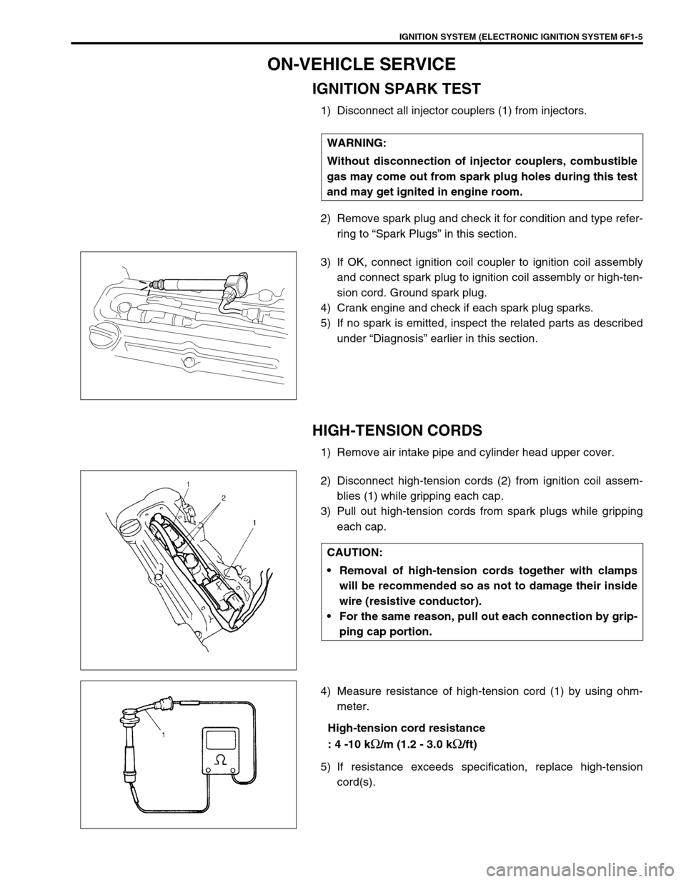
IGNITION SPARK TEST
1) Disconnect all injector couplers (1) from injectors.
2) Remove spark plug and check it for condition and type refer-
ring to “Spark Plugs” in this section.
3) If OK, connect ignition coil coupler to ignition coil assembly
and connect spark plug to ignition coil assembly or high-ten-
sion cord. Ground spark plug.
4) Crank engine and check if each spark plug sparks.
5) If no spark is emitted, inspect the related parts as described
under “Diagnosis” earlier in this section.
HIGH-TENSION CORDS
1) Remove air intake pipe and cylinder head upper cover.
2) Disconnect high-tension cords (2) from ignition coil assem-
blies (1) while gripping each cap.
3) Pull out high-tension cords from spark plugs while gripping
each cap.
4) Measure resistance of high-tension cord (1) by using ohm-
meter.
High-tension cord resistance
: 4 -10 k
Ω/m (1.2 - 3.0 kΩ/ft)
5) If resistance exceeds specification, replace high-tension
cord(s). WARNING:
Without disconnection of injector couplers, combustible
gas may come out from spark plug holes during this test
and may get ignited in engine room.
CAUTION:
Removal of high-tension cords together with clamps
will be recommended so as not to damage their inside
wire (resistive conductor).
For the same reason, pull out each connection by grip-
ping cap portion.
Page 675 of 698

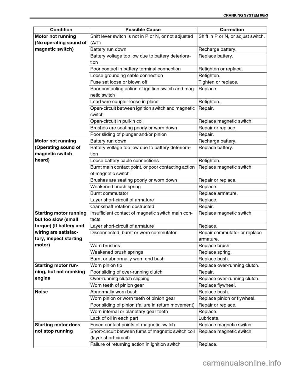
CRANKING SYSTEM 6G-3
Condition Possible Cause Correction
Motor not running
(No operating sound of
magnetic switch)Shift lever switch is not in P or N, or not adjusted
(A/T)Shift in P or N, or adjust switch.
Battery run down Recharge battery.
Battery voltage too low due to battery deteriora-
tionReplace battery.
Poor contact in battery terminal connection Retighten or replace.
Loose grounding cable connection Retighten.
Fuse set loose or blown off Tighten or replace.
Poor contacting action of ignition switch and mag-
netic switchReplace.
Lead wire coupler loose in place Retighten.
Open-circuit between ignition switch and magnetic
switchRepair.
Open-circuit in pull-in coil Replace magnetic switch.
Brushes are seating poorly or worn down Repair or replace.
Poor sliding of plunger and/or pinion Repair.
Motor not running
(Operating sound of
magnetic switch
heard)Battery run down Recharge battery.
Battery voltage too low due to battery deteriora-
tionReplace battery.
Loose battery cable connections Retighten.
Burnt main contact point, or poor contacting action
of magnetic switchReplace magnetic switch.
Brushes are seating poorly or worn down Repair or replace.
Weakened brush spring Replace.
Burnt commutator Replace armature.
Layer short-circuit of armature Replace.
Crankshaft rotation obstructed Repair.
Starting motor running
but too slow (small
torque) (If battery and
wiring are satisfac-
tory, inspect starting
motor)Insufficient contact of magnetic switch main con-
tactsReplace magnetic switch.
Layer short-circuit of armature Replace.
Disconnected, burnt or worn commutator Repair commutator or replace
armature.
Worn brushes Replace brush.
Weakened brush springs Replace spring.
Burnt or abnormally worn end bush Replace bush.
Starting motor run-
ning, but not cranking
engineWorn pinion tip Replace over-running clutch.
Poor sliding of over-running clutch Repair.
Over-running clutch slipping Replace over-running clutch.
Worn teeth of pinion gear Replace flywheel.
Noise
Abnormally worn bush Replace bush.
Worn pinion or worn teeth of pinion gear Replace pinion or flywheel.
Poor sliding of pinion (failure in return movement) Repair or replace.
Worn internal or planetary gear teeth Replace.
Lack of oil in each part Lubricate.
Starting motor does
not stop runningFused contact points of magnetic switch Replace magnetic switch.
Short-circuit between turns of magnetic switch coil
(layer short-circuit)Replace magnetic switch.
Failure of returning action in ignition switch Replace.
Page 681 of 698

CHARGING SYSTEM 6H-1
6F1
6F2
6G
6K
7A
6H
7B1
7C1
7D
7E
7F
8A
8B
8C
8D
8E
9
10
10A
10B
SECTION 6H
CHARGING SYSTEM
CONTENTS
GENERAL DESCRIPTION .............................. 6H-2
BATTERY ..................................................... 6H-2
CARRIER AND HOLD-DOWN ................. 6H-2
ELECTROLYTE FREEZING .................... 6H-2
SULFATION ............................................. 6H-2
BUILT-IN INDICATOR (IF EQUIPPED) ... 6H-2
CARE OF BATTERY ................................ 6H-3
GENERATOR .............................................. 6H-4
DIAGNOSIS ..................................................... 6H-5
BATTERY ..................................................... 6H-5
VISUAL INSPECTION.............................. 6H-5
HYDROMETER TEST.............................. 6H-5
GENERATOR .............................................. 6H-6
CHARGING INDICATOR LAMP
OPERATION ............................................ 6H-6
UNDERCHARGED BATTERY ................. 6H-7
OVERCHARGED BATTERY.................... 6H-8ON-VEHICLE SERVICE .................................. 6H-9
BATTERY .................................................... 6H-9
JUMP STARTING IN CASE OF
EMERGENCY .......................................... 6H-9
DISMOUNTING...................................... 6H-10
HANDLING............................................. 6H-10
REMOUNTING....................................... 6H-10
GENERATOR ............................................ 6H-10
GENERATOR BELT .............................. 6H-10
DISMOUNTING AND REMOUNTING ... 6H-11
DISASSEMBLY AND REASSEMBLY .... 6H-11
INSPECTION ......................................... 6H-12
SPECIFICATION ........................................... 6H-14
BATTERY .................................................. 6H-14
GENERATOR ............................................ 6H-14
TIGHTENING TORQUE SPECIFICATION.... 6H-14
WARNING:
For vehicles equipped with Supplemental Restraint (Air Bag) System:
Service on and around the air bag system components or wiring must be performed only by an
authorized SUZUKI dealer. Refer to “Air Bag System Components and Wiring Location View” under
“General Description” in air bag system section in order to confirm whether you are performing ser-
vice on or near the air bag system components or wiring. Please observe all WARNINGS and “Ser-
vice Precautions” under “On-Vehicle Service” in air bag system section before performing service
on or around the air bag system components or wiring. Failure to follow WARNINGS could result in
unintentional activation of the system or could render the system inoperative. Either of these two
conditions may result in severe injury.
Technical service work must be started at least 90 seconds after the ignition switch is turned to the
“LOCK” position and the negative cable is disconnected from the battery. Otherwise, the system
may be activated by reserve energy in the Sensing and Diagnostic Module (SDM).
Page 686 of 698

6H-6 CHARGING SYSTEM
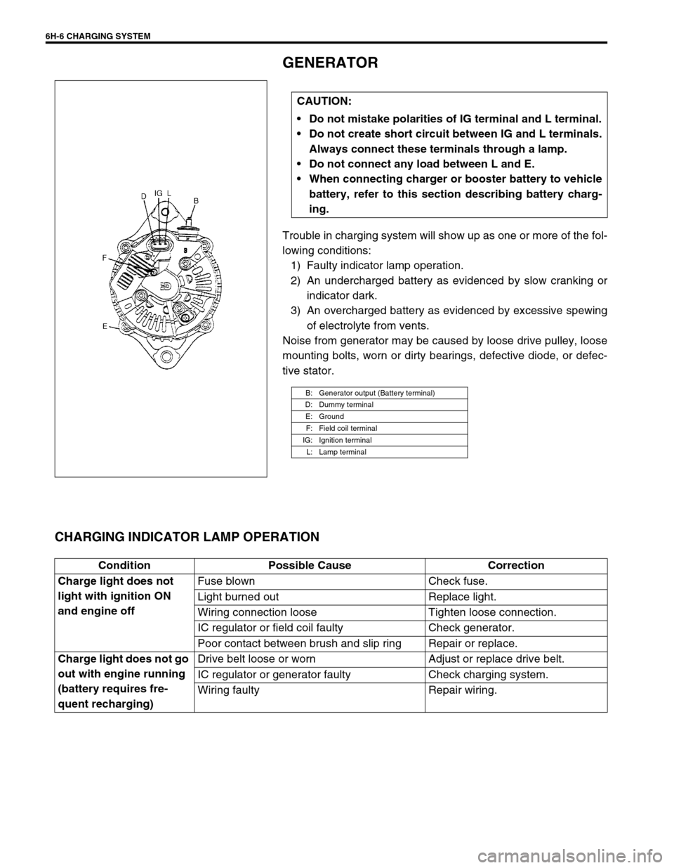
GENERATOR
Trouble in charging system will show up as one or more of the fol-
lowing conditions:
1) Faulty indicator lamp operation.
2) An undercharged battery as evidenced by slow cranking or
indicator dark.
3) An overcharged battery as evidenced by excessive spewing
of electrolyte from vents.
Noise from generator may be caused by loose drive pulley, loose
mounting bolts, worn or dirty bearings, defective diode, or defec-
tive stator.
CHARGING INDICATOR LAMP OPERATION
CAUTION:
Do not mistake polarities of IG terminal and L terminal.
Do not create short circuit between IG and L terminals.
Always connect these terminals through a lamp.
Do not connect any load between L and E.
When connecting charger or booster battery to vehicle
battery, refer to this section describing battery charg-
ing.
B: Generator output (Battery terminal)
D: Dummy terminal
E: Ground
F: Field coil terminal
IG: Ignition terminal
L: Lamp terminal
Condition Possible Cause Correction
Charge light does not
light with ignition ON
and engine offFuse blown Check fuse.
Light burned out Replace light.
Wiring connection loose Tighten loose connection.
IC regulator or field coil faulty Check generator.
Poor contact between brush and slip ring Repair or replace.
Charge light does not go
out with engine running
(battery requires fre-
quent recharging)Drive belt loose or worn Adjust or replace drive belt.
IC regulator or generator faulty Check charging system.
Wiring faulty Repair wiring.
Page 688 of 698

6H-8 CHARGING SYSTEM
3) Ground F terminal and start engine, then measure voltage at
B terminal as shown in left figure.
Voltage is higher than standard value
It is considered that generator itself is good but IC regulator
has been damaged, replace IC regulator.
Voltage is lower than standard value
Generator itself has problem, check the generator.
LOAD CHECK
1) Run engine at 2,000 rpm and turn on head light and heater
motor.
2) Measure current and if it is less than 20 A repair or replace
generator.
OVERCHARGED BATTERY
1) To determine battery condition, refer to Battery section.
2) If obvious overcharge condition exists as evidenced by
excessive spewing of electrolyte, measure generator B ter-
minal voltage at engine 2000 rpm.
3) If measured voltage is higher than upper limit value, disas-
semble generator.
4) Check ground of brushes. If brushes are not grounded,
replace IC regulator. Then check field coil for grounds and
shorts.
A: Regulated voltage (V)
B: Heatsink temperature (°C)
16.0
15.5
14.2 15.3
14.8
14.2
13.314.8
15.0
14.5
14.0
13.5
13.0
-30 0 25 135
[A]
[B]