Page 137 of 698

3B-16 MANUAL RACK AND PINION
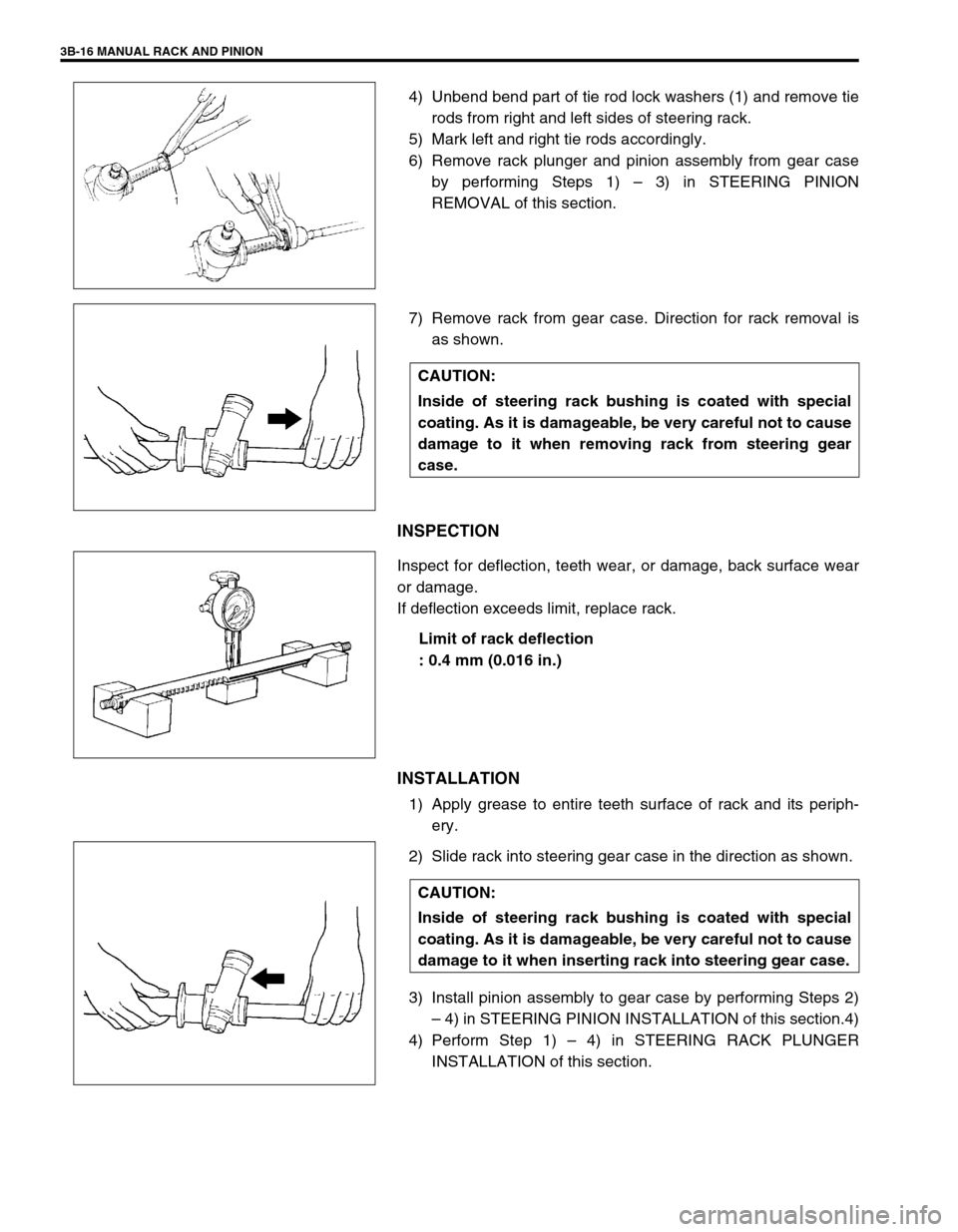
4) Unbend bend part of tie rod lock washers (1) and remove tie
rods from right and left sides of steering rack.
5) Mark left and right tie rods accordingly.
6) Remove rack plunger and pinion assembly from gear case
by performing Steps 1) – 3) in STEERING PINION
REMOVAL of this section.
7) Remove rack from gear case. Direction for rack removal is
as shown.
INSPECTION
Inspect for deflection, teeth wear, or damage, back surface wear
or damage.
If deflection exceeds limit, replace rack.
Limit of rack deflection
: 0.4 mm (0.016 in.)
INSTALLATION
1) Apply grease to entire teeth surface of rack and its periph-
ery.
2) Slide rack into steering gear case in the direction as shown.
3) Install pinion assembly to gear case by performing Steps 2)
– 4) in STEERING PINION INSTALLATION of this section.4)
4) Perform Step 1) – 4) in STEERING RACK PLUNGER
INSTALLATION of this section.
CAUTION:
Inside of steering rack bushing is coated with special
coating. As it is damageable, be very careful not to cause
damage to it when removing rack from steering gear
case.
CAUTION:
Inside of steering rack bushing is coated with special
coating. As it is damageable, be very careful not to cause
damage to it when inserting rack into steering gear case.
Page 138 of 698
MANUAL RACK AND PINION 3B-17
5) Before installing boot to steering rack housing (1), make sure
that rack side mount (2) is positioned as shown. Install tie
rods to rack by performing Steps 1) – 6) in RACK BOOT/TIE
ROD INSTALLATION of this section.
Rack side mount installing position
“a” : 5.1 mm (0.2 in.)
PINION BEARING
REMOVAL
1) Remove rack from steering gear case, referring to STEER-
ING RACK REMOVAL of this section.
2) Remove pinion bearing (1) from gear case with special tools
as shown.
Special tool
(A) : 09921-20200
(B) : 09930-30102
INSTALLATION
1) Apply grease to rollers of pinion bearing.
2) Press-fit pinion bearing (1) into gear case with special tool as
shown.
After press-fitting, make sure that bearing rollers are
installed properly.
Special tool
(A) : 09943-88211
3) Follow Steps 1) – 5) in STEERING RACK INSTALLATION of
this section to complete installation.
Page 139 of 698
3B-18 MANUAL RACK AND PINION
RACK BUSHING
REMOVAL
1) Remove rack from steering gear case, referring to STEER-
ING RACK REMOVAL of this section.
2) Remove snap ring (2).
3) Pull out bushing from rack housing with special tool as
shown.
Special tool
(A) : 09944-48210
INSPECTION
Inspect rack bushing for wear or damage.
If found defective, replace.NOTE:
When removing rack bushing, be careful not to pull out
bushing by holding gear case in a vise. Or housing (pipe)
may come off gear case. For this work, be sure to use the
below specified special tool.
1. Rack housing
3. Bushing
Page 140 of 698

MANUAL RACK AND PINION 3B-19
INSTALLATION
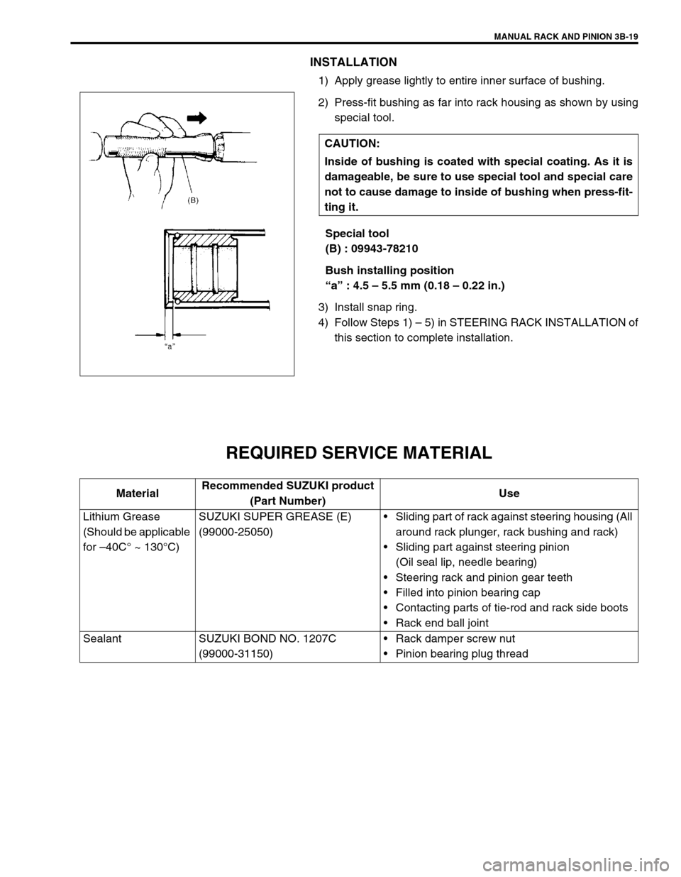
1) Apply grease lightly to entire inner surface of bushing.
2) Press-fit bushing as far into rack housing as shown by using
special tool.
Special tool
(B) : 09943-78210
Bush installing position
“a” : 4.5 – 5.5 mm (0.18 – 0.22 in.)
3) Install snap ring.
4) Follow Steps 1) – 5) in STEERING RACK INSTALLATION of
this section to complete installation.
REQUIRED SERVICE MATERIAL
CAUTION:
Inside of bushing is coated with special coating. As it is
damageable, be sure to use special tool and special care
not to cause damage to inside of bushing when press-fit-
ting it.
MaterialRecommended SUZUKI product
(Part Number)Use
Lithium Grease
(Should be applicable
for –40C° ~ 130°C)SUZUKI SUPER GREASE (E)
(99000-25050)Sliding part of rack against steering housing (All
around rack plunger, rack bushing and rack)
Sliding part against steering pinion
(Oil seal lip, needle bearing)
Steering rack and pinion gear teeth
Filled into pinion bearing cap
Contacting parts of tie-rod and rack side boots
Rack end ball joint
Sealant SUZUKI BOND NO. 1207C
(99000-31150)Rack damper screw nut
Pinion bearing plug thread
Page 141 of 698
3B-20 MANUAL RACK AND PINION
SPECIAL TOOL
09913-65210 09913-50121 09921-20200 09925-98210
Tie-rod end remover Oil seal remover Pinion bearing remover Bearing installer
09930-30102 09943-78210 09944-18211 09944-26011
Sliding shaft Rack bush installer Pinion torque checking
socket43 mm Socket (Pinion
bearing plug remover)
09944-48210
Rack bush remover
Page 142 of 698

ELECTRICAL POWER STEERING (P/S) SYSTEM 3B1-1
6F1
6F2
6G
6H
6K
7A
7A1
3B1
7D
7E
7F
8A
8B
8C
8D
8E
9
10
10A
10B
SECTION 3B1
ELECTRICAL POWER STEERING (P/S) SYSTEM
CONTENTS
GENERAL DESCRIPTION .............................3B1-2
SYSTEM COMPONENTS ........................... 3B1-2
WIRING DIAGRAM ..................................... 3B1-3
DIAGNOSIS ....................................................3B1-4
ON-BOARD DIAGNOSTIC SYSTEM .......... 3B1-4
PRECAUTIONS IN DIAGNOSING
TROUBLES ................................................. 3B1-4
SYSTEM CHECK FLOW TABLE ................ 3B1-5
MALFUNCTION INDICATOR LAMP
(“EPS” WARNING LAMP) CHECK.............. 3B1-7
DTC CHECK ............................................... 3B1-8
DTC CLEARANCE ...................................... 3B1-9
SERIAL DATA LINK CIRCUIT CHECK ..... 3B1-10
DTC TABLE .............................................. 3B1-11
TABLE A - MALFUNCTION INDICATOR
LAMP DOES NOT COME ON AT
IGNITION SWITCH ON BUT LEAVING
ENGINE OFF ............................................ 3B1-13
TABLE B - MALFUNCTION INDICATOR
LAMP FLASHES AT IGNITION SWITCH
ON ............................................................. 3B1-15
TABLE C - MALFUNCTION INDICATOR
LAMP DOES NOT FLASH, JUST
REMAINS ON OR JUST REMAINS OFF
EVEN WITH DIAGNOSIS SWITCH
TERMINAL GROUNDED .......................... 3B1-15
DTC C1111 (DTC No.11) TORQUE
SENSOR MAIN CIRCUIT FAILURE ......... 3B1-16
DTC C1113 (DTC No.13) TORQUE
SENSOR MAIN AND SUB CIRCUIT
FAILURE ................................................... 3B1-16DTC C1115 (DTC No.15) TORQUE
SENSOR SUB CIRCUIT FAILURE........... 3B1-16
DTC C1114 (DTC No.14) TORQUE
SENSOR 5V POWER SUPPLY CIRCUIT
FAILURE ................................................... 3B1-17
DTC C1116 (DTC No.16) TORQUE
SENSOR 8V POWER SUPPLY CIRCUIT
FAILURE ................................................... 3B1-18
DTC C1121/C1123/C1124
(DTC No.21/23/24) VSS CIRCUIT
FAILURE ................................................... 3B1-19
DTC C1122 (DTC No.22) ENGINE
SPEED SIGNAL CIRCUIT FAILURE ........ 3B1-20
DTC C1141/C1142/C1143/C1144/C1145
(DTC No.41/42/43/44/45) MOTOR
CIRCUIT FAILURE ................................... 3B1-21
DTC C1151 (DTC No.51) CLUTCH
CIRCUIT FAILURE ................................... 3B1-22
DTC C1153(DTC No.53) P/S CONTROL
MODULE POWER SUPPLY CIRCUIT
FAILURE ................................................... 3B1-24
DTC C1152/C1154/C1155
(DTC No.52/54/55) P/S CONTROL
MODULE FAILURE .................................. 3B1-24
TROUBLE DIAGNOSIS (FOR TROUBLE
NOT INDICATED BY ON BOARD
DIAGNOSTIC SYSTEM)........................... 3B1-25
INSPECTION OF P/S CONTROL
MODULE AND ITS CIRCUITS ................. 3B1-26
STEERING WHEEL PLAY
INSPECTION ............................................ 3B1-28 WARNING:
For vehicles equipped with Supplemental Restraint (Air Bag) System :
Service on and around the air bag system components or wiring must be performed only by an
authorized SUZUKI dealer. Refer to “Air Bag System Components and Wiring Location View” under
“General Description” in air bag system section in order to confirm whether you are performing ser-
vice on or near the air bag system components or wiring. Please observe all WARNINGS and “Ser-
vice Precautions” under “On-Vehicle Service” in air bag system section before performing service
on or around the air bag system components or wiring. Failure to follow WARNINGS could result in
unintentional activation of the system or could render the system inoperative. Either of these two
conditions may result in severe injury.
Technical service work must be started at least 90 seconds after the ignition switch is turned to the
“LOCK” position and the negative cable is disconnected from the battery. Otherwise, the system
may be activated by reserve energy in the Sensing and Diagnostic Module (SDM).
Page 143 of 698

3B1-2 ELECTRICAL POWER STEERING (P/S) SYSTEM
STEERING FORCE INSPECTION ........... 3B1-28
ON-VEHICLE SERVICE ............................... 3B1-29
P/S CONTROL MODULE ......................... 3B1-29
TORQUE SENSOR .................................. 3B1-29MOTOR AND CLUTCH ............................ 3B1-30
STEERING COLUMN ASSEMBLY .......... 3B1-31
SPECIAL TOOL ........................................... 3B1-31
GENERAL DESCRIPTION
SYSTEM COMPONENTS
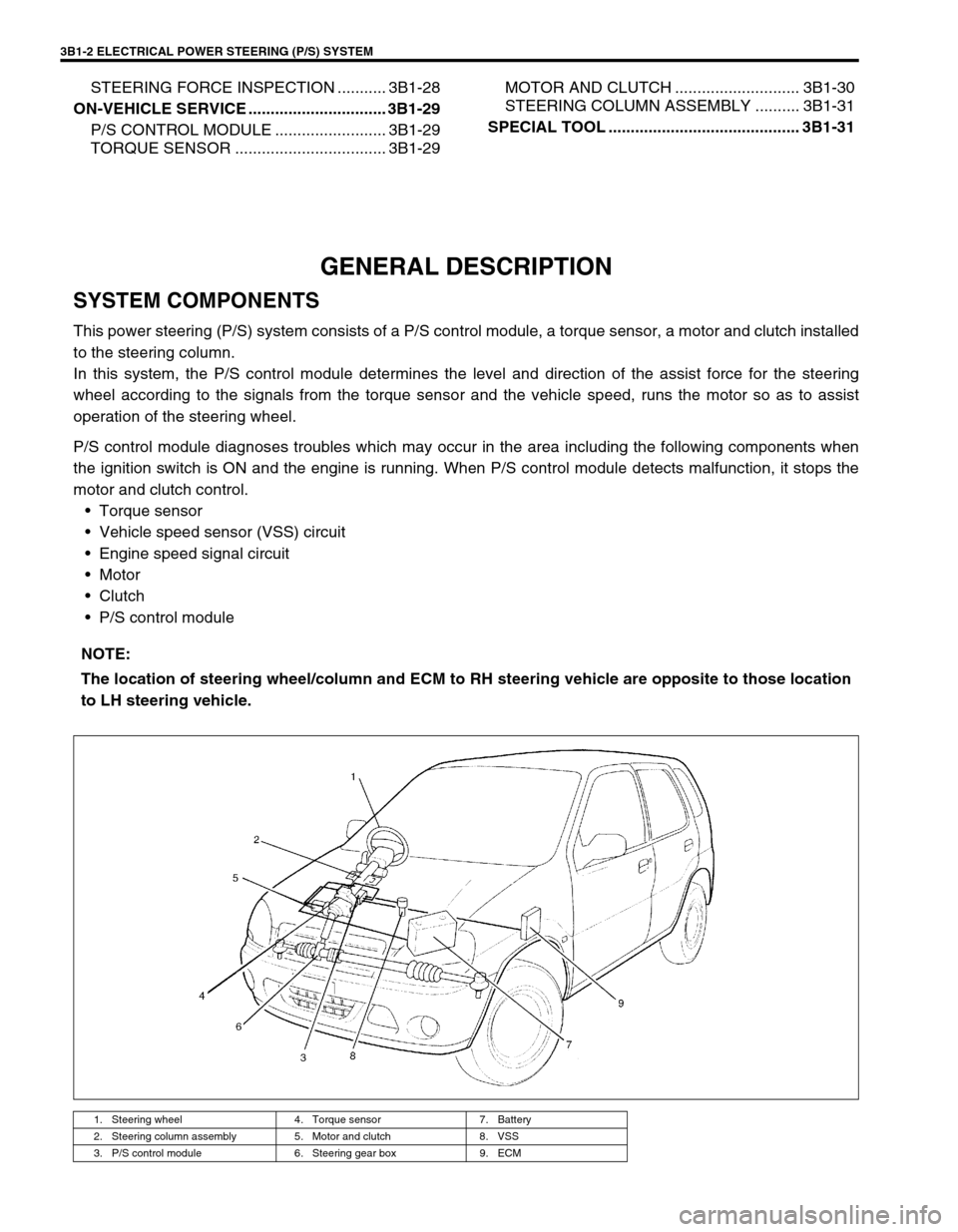
This power steering (P/S) system consists of a P/S control module, a torque sensor, a motor and clutch installed
to the steering column.
In this system, the P/S control module determines the level and direction of the assist force for the steering
wheel according to the signals from the torque sensor and the vehicle speed, runs the motor so as to assist
operation of the steering wheel.
P/S control module diagnoses troubles which may occur in the area including the following components when
the ignition switch is ON and the engine is running. When P/S control module detects malfunction, it stops the
motor and clutch control.
Torque sensor
Vehicle speed sensor (VSS) circuit
Engine speed signal circuit
Motor
Clutch
P/S control module
NOTE:
The location of steering wheel/column and ECM to RH steering vehicle are opposite to those location
to LH steering vehicle.
1. Steering wheel 4. Torque sensor 7. Battery
2. Steering column assembly 5. Motor and clutch 8. VSS
3. P/S control module 6. Steering gear box 9. ECM
Page 144 of 698
ELECTRICAL POWER STEERING (P/S) SYSTEM 3B1-3
WIRING DIAGRAM
BLK RED
BLK
BLK
BLU
BLK YEL BLU
BLK
YEL
WHT
BRN
PPLBLK/WHT
BLK/RED
PPL/WHTBLK or RED
RED or BLK G24-1-1 G24-2-2
G24-2-1
G24-2-4
G24-2-3
G24-5
G24-3
G24-4
G24-2 G24-1-2
G24-1-3
G24-1-4
G24-1-5
G24-6
G24-8
G24-1 G24-7 12
5
6
124
378
9171611 10
G24-1
G24-3
G24-4
G24-5
G24-6
G24-7G24-8G24-2
13
G24-2-2
G24-2-4 G24-2-3 G24-2-1
14
G24-1-5
G24-1-4 G24-1-3 G24-1-2 G24-1-115
1. Main fuse 7. Monitor coupler (for A/T, ABS, P/S system) 13. Connector “G24”
2. Ignition switch 8. Diagnosis switch terminal (for P/S system) 14. Connector “G24-2”
3.“P/S” fuse (30A) in fuse box 9. Ground terminal 15. Connector “G24-1”
4.“IG METER” fuse (15A) in fuse box 10. P/S control module 16.“EPS” warning lamp
5. ECM 11. Motor and clutch 17. DLC
6. VSS 12. Torque sensor