Page 316 of 698
BRAKES 5-43
For vehicle without ABS
T : Top side 1. From master cylinder primary to left front brake [A] : For left-hand steering vehicle
F : Front side 2. From master cylinder secondary to right front brake [B] : For right-hand steering vehicle
R : Right side 3. Master cylinder a-g: Clamp
A : View A 4. Front brake hose Tightening torque
Page 328 of 698

ANTILOCK BRAKE SYSTEM (ABS) 5E-3
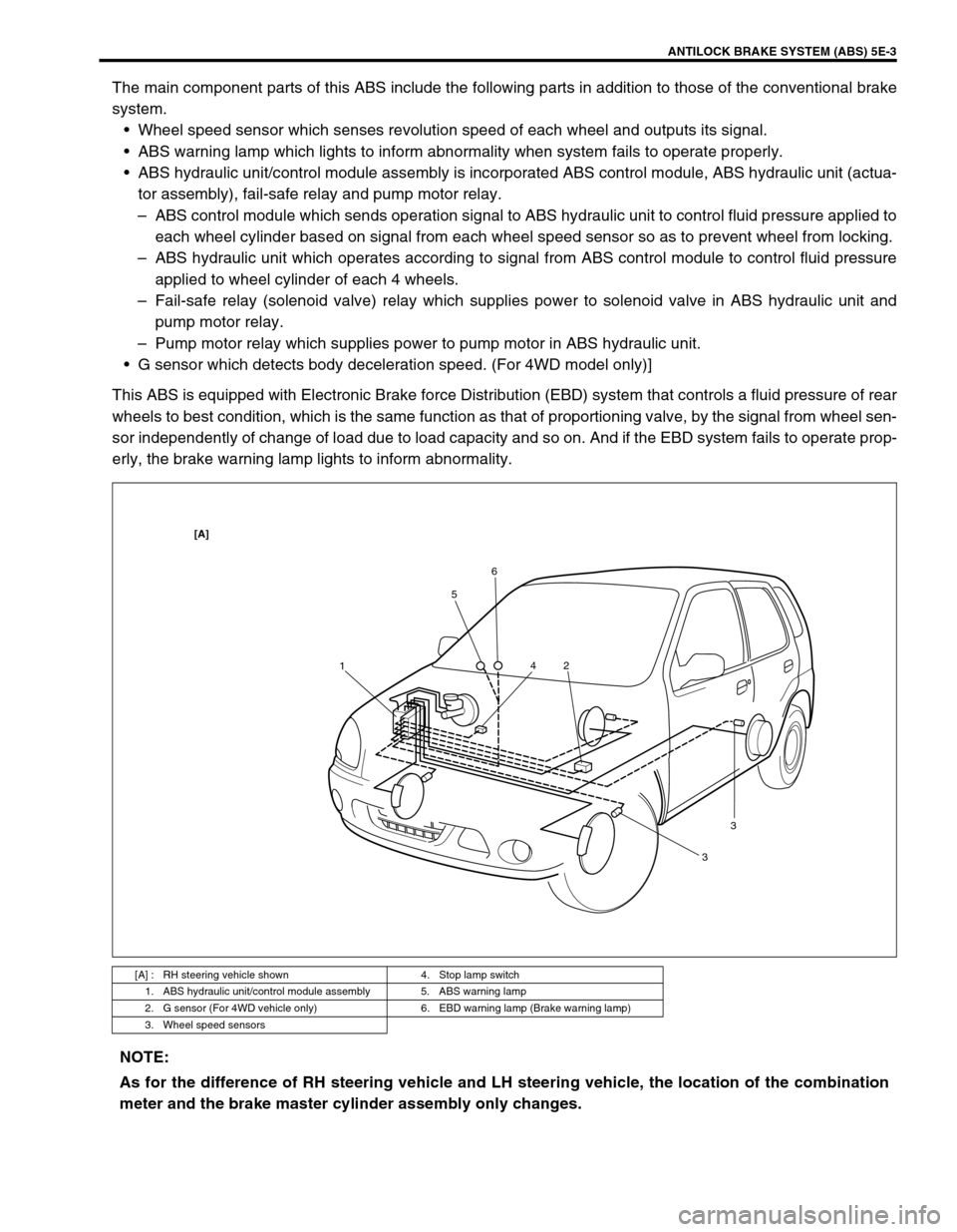
The main component parts of this ABS include the following parts in addition to those of the conventional brake
system.
Wheel speed sensor which senses revolution speed of each wheel and outputs its signal.
ABS warning lamp which lights to inform abnormality when system fails to operate properly.
ABS hydraulic unit/control module assembly is incorporated ABS control module, ABS hydraulic unit (actua-
tor assembly), fail-safe relay and pump motor relay.
–ABS control module which sends operation signal to ABS hydraulic unit to control fluid pressure applied to
each wheel cylinder based on signal from each wheel speed sensor so as to prevent wheel from locking.
–ABS hydraulic unit which operates according to signal from ABS control module to control fluid pressure
applied to wheel cylinder of each 4 wheels.
–Fail-safe relay (solenoid valve) relay which supplies power to solenoid valve in ABS hydraulic unit and
pump motor relay.
–Pump motor relay which supplies power to pump motor in ABS hydraulic unit.
G sensor which detects body deceleration speed. (For 4WD model only)]
This ABS is equipped with Electronic Brake force Distribution (EBD) system that controls a fluid pressure of rear
wheels to best condition, which is the same function as that of proportioning valve, by the signal from wheel sen-
sor independently of change of load due to load capacity and so on. And if the EBD system fails to operate prop-
erly, the brake warning lamp lights to inform abnormality.
[A] : RH steering vehicle shown 4. Stop lamp switch
1. ABS hydraulic unit/control module assembly 5. ABS warning lamp
2. G sensor (For 4WD vehicle only) 6. EBD warning lamp (Brake warning lamp)
3. Wheel speed sensors
156
2 4
33
[A]
NOTE:
As for the difference of RH steering vehicle and LH steering vehicle, the location of the combination
meter and the brake master cylinder assembly only changes.
Page 406 of 698

ENGINE GENERAL INFORMATION AND DIAGNOSIS 6-37
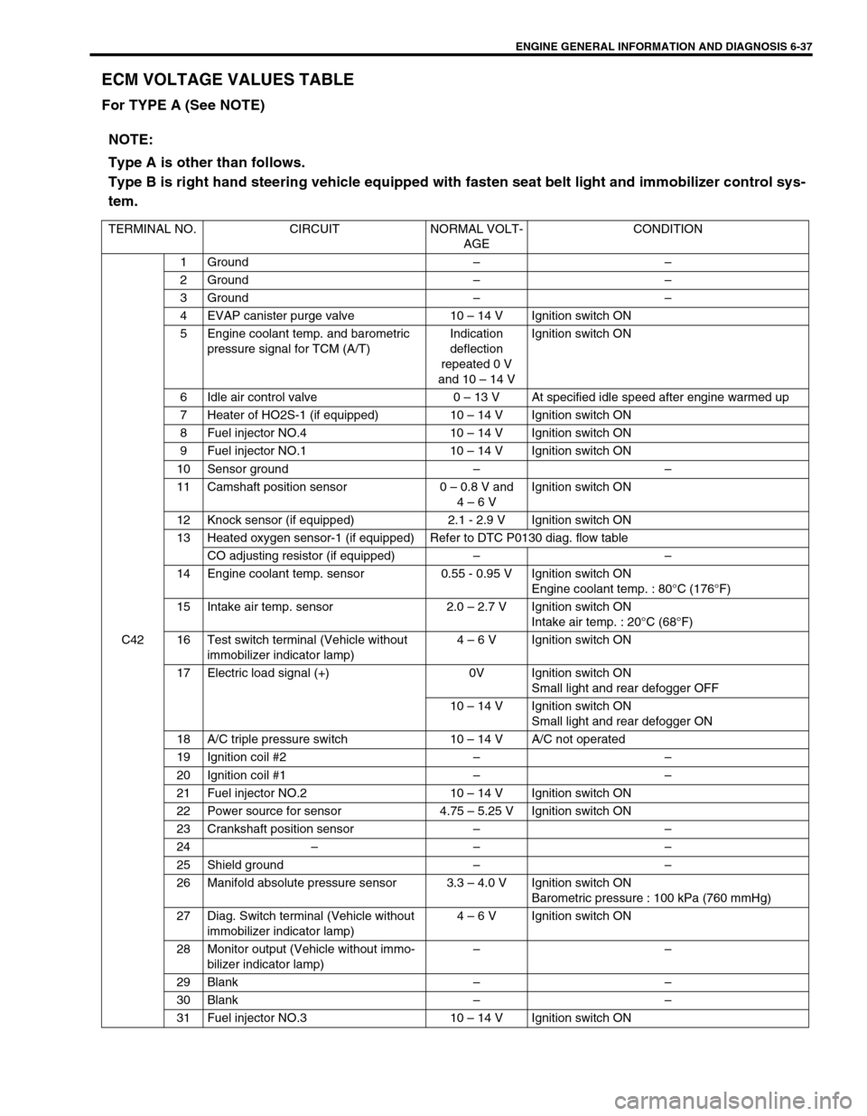
ECM VOLTAGE VALUES TABLE
For TYPE A (See NOTE)
NOTE:
Type A is other than follows.
Type B is right hand steering vehicle equipped with fasten seat belt light and immobilizer control sys-
tem.
TERMINAL NO. CIRCUIT NORMAL VOLT-
AGECONDITION
C421 Ground––
2 Ground––
3 Ground––
4 EVAP canister purge valve 10 – 14 V Ignition switch ON
5 Engine coolant temp. and barometric
pressure signal for TCM (A/T)Indication
deflection
repeated 0 V
and 10 – 14 VIgnition switch ON
6 Idle air control valve 0 – 13 V At specified idle speed after engine warmed up
7 Heater of HO2S-1 (if equipped) 10 – 14 V Ignition switch ON
8 Fuel injector NO.4 10 – 14 V Ignition switch ON
9 Fuel injector NO.1 10 – 14 V Ignition switch ON
10 Sensor ground––
11 Camshaft position sensor 0 – 0.8 V and
4 – 6 VIgnition switch ON
12 Knock sensor (if equipped) 2.1 - 2.9 V Ignition switch ON
13 Heated oxygen sensor-1 (if equipped) Refer to DTC P0130 diag. flow table
CO adjusting resistor (if equipped)––
14 Engine coolant temp. sensor 0.55 - 0.95 V Ignition switch ON
Engine coolant temp. : 80°C (176°F)
15 Intake air temp. sensor 2.0 – 2.7 V Ignition switch ON
Intake air temp. : 20°C (68°F)
16 Test switch terminal (Vehicle without
immobilizer indicator lamp)4 – 6 V Ignition switch ON
17 Electric load signal (+) 0V Ignition switch ON
Small light and rear defogger OFF
10 – 14 V Ignition switch ON
Small light and rear defogger ON
18 A/C triple pressure switch 10 – 14 V A/C not operated
19 Ignition coil #2––
20 Ignition coil #1––
21 Fuel injector NO.2 10 – 14 V Ignition switch ON
22 Power source for sensor 4.75 – 5.25 V Ignition switch ON
23 Crankshaft position sensor––
24–– –
25 Shield ground––
26 Manifold absolute pressure sensor 3.3 – 4.0 V Ignition switch ON
Barometric pressure : 100 kPa (760 mmHg)
27 Diag. Switch terminal (Vehicle without
immobilizer indicator lamp)4 – 6 V Ignition switch ON
28 Monitor output (Vehicle without immo-
bilizer indicator lamp)––
29 Blank––
30 Blank––
31 Fuel injector NO.3 10 – 14 V Ignition switch ON
Page 414 of 698
ENGINE GENERAL INFORMATION AND DIAGNOSIS 6-45
COMPONENT LOCATION
1. TP sensor 9. Radiator fan control relay No.3 17. ECM
2. MAP sensor 10. EVAP canister purge valve 18. Monitor connector
3. IAC valve 11. ECT sensor 19. VSS
4. IAT sensor 12. Ignition coil with igniter 20. Knock sensor (if equipped)
5. Radiator fan control relay No.1 13. HO2S-1 (if equipped) 21. CMP sensor
6. Main relay 14. HO2S-2 (if equipped) 22. EGR valve (if equipped)
7. Fuel pump relay 15. CKP sensor✱ : This figure shows left-hand steering vehicle, these parts are
installed at the other side for right-hand steering vehicle.
8. Radiator fan control relay No.2 16. TCM
1
3
24
518
6 7
20
19
8
9 1617
21
15
131214
10
22
11
Page 571 of 698
6A1-70 ENGINE MECHANICAL (M13 ENGINE)
15) Remove exhaust No.1 pipe (1).
16) Disconnect right and left drive shaft joints from differential
gear referring to Section 4.
For engine and transmission removal, it is not necessary to
remove drive shafts from steering knuckle.
17) For 4WD vehicle, remove propeller shaft referring to Section
4B.
18) Remove generator referring to Section 6H.
19) Install lifting device.
20) Remove engine rear mounting bolts (1), engine left mounting
bracket nuts (2) and engine right mounting bolts (3).
Page 630 of 698

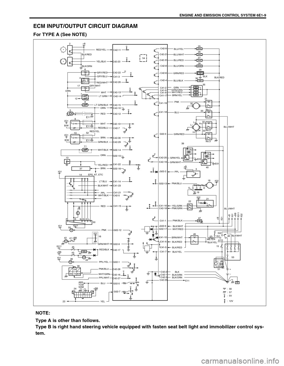
ENGINE AND EMISSION CONTROL SYSTEM 6E1-9
ECM INPUT/OUTPUT CIRCUIT DIAGRAM
For TYPE A (See NOTE)
37
C41-23
G02-12 IG1PNK 5554
BLK
C41-2
C41-9
C41-8
C41-17C42-13
17
2+B
1
6
8
5
IG1
IG1
14C42-9
C42-11
C42-23
C42-22
C41-3
C42-26
C42-14
C42-15
C42-10
C42-12
C42-13
C42-7
C42-30
C42-29
G02-14
G02-10
G02-16
C41-14
C41-21
C42-5
C41-15
G02-9
C42-17
G02-1
C42-28
C42-27 C42-16
G02-5C42-21
C42-31
C42-8
C42-6
C42-4
C41-19
C41-18
G02-3
G02-2
G02-13
C41-16
C42-18
C41-1
C41-10
C41-6
C41-5
C41-7
C42-1 C42-2
C42-3
C42-25G02-6
G02-173E01
E01 C42-20
C42-19L+
L–
H–H+ 25
26
27
28
29
30
35
31
No.1
No.2
No.3 32
33
33
33 34
IG2
IG2
+B
+B
IG1
+BB
IG11
IG2 IG1
21
47
49
IG
METERIG1
ST
15IG2
48
53
E11+
– 2218
PRND2L
IG11
IG11
+BB
IG145 41
ABS
TCM
SDM
24IG1
+BB50
16
E11
E1194
7
12
+BB
GND
: 56 : 57
IG1
E11 10
11
+B RED/YELBLU/YEL
BLU/WHT
BLU/RED
BLU/ORN
GRN/RED
BLU/BLK
PNK
BLU
GRN/RED
GRN/YEL39
40 GRN/WHT
PPL
YEL/GRN PNK/BLU
PNK/GRN
PNK/BLK
BLK/WHT
WHT/RED
BRN/WHT
BLK/RED
BLK/RED
BLK/YEL
BLK/ORNBLK
BLK/ORN YEL/BLK
GRY/RED
GRY/BLU
RED/WHT
GRY/WHT
LT GRN
LT GRN/BLK
ORN
RED
WHT
RED/BLU
BRN
GRN/BLK
WHT/BLK
ORN
BRN
EPS, AT, ETC
LT BLU
PPL
WHT/BLK
GRN/WHT
RED/BLK
PPL/YEL
PNK/BLU
WHT/GRN
BLU
B/W
B/W
BLK/WHT
RED
42
46 43
44 36
DN
TSGND MONPPL/WHT 38
G02-7
YEL
BLK/RED
GRN
GRN/ORN
BRN/YEL
51
2352
C41-22YEL/RED 13WHT
19
ORN
: 5V
: 12V
BLU/WHT
BLK/WHT
BLU/WHT
BLK/YEL
BLK/RED
BLK/ORN
WHT/RED
RED/YEL
NOTE:
Type A is other than follows.
Type B is right hand steering vehicle equipped with fasten seat belt light and immobilizer control sys-
tem.